manuals.online logo
Brands
  1. Home
  2. •
  3. Brands
  4. •
  5. Lindsay
  6. •
  7. Control System
  8. •
  9. Lindsay Barrier Systems ARMORGUARD NCHRP 350 TL-3 User manual

Lindsay Barrier Systems ARMORGUARD NCHRP 350 TL-3 User manual

INSTALLATION AND MAINTENANCE MANUAL
ARMORGUARD®BARRIER
NCHRP 350 TL-3 Movable Longitudinal Steel Barrier
ARMORGUARD® BARRIER
NCHRP 350 TL-3 Movable Longitudinal Steel Barrier
1823784 - Installation and Maintenance Manual
INSTALLATION INSTRUCTIONS
Rev A ECN 60881
Barrier Systems by Lindsay +1 (888) 800-3691 (U.S. toll free or +1 (402) 829-6800 - ECN 60881 Barrier Systems by Lindsay +1 (888) 800-3691 (U.S. toll free or +1 (402) 829-6800 - ECN 60881
2
INSTALLATION AND MAINTENANCE MANUAL
Installation and Maintenance
Manual Supplement
ARMORGUARD®BARRIER
PREFACE
The ArmorGuard Barrier (AGB) incorporates the newest
roadside safety materials and engineering processes.
As with any roadside safety device, the AGB must
be installed and operated properly to insure proper
performance. Thoroughly review and fully understand
the installation instructions and product limitations
before starting the installation. Do not start the
installation without the proper plans and tools required
for installation.
If you need additional information or have questions
about the ArmorGuard Barrier please call the
Lindsay Transportation Solutions Customer Service
Department at (888) 800-3691 (U.S. toll free) or (707)
374-6800.
Lindsay Transportation Solutions Sales and Services, Inc (888) 800-3691 [U.S. toll free] or +1 (707) 374-6800 Lindsay Transportation Solutions Sales and Services, Inc (888) 800-3691 [U.S. toll free] or +1 (707) 374-6800
2
ArmorGuard Barrier
Installation Manual
Table of contents
Preface 2
Warranty 3
Applications and System Characteristics 4
Introduction 5
System Overview 5
Required Tools 5
Before Installation 5
Deploying ArmorGuard Barrier at the Jobsite
Picking up a Barrier 6
Operational Instructions
Manual Jacking System 6
Air Lift Control Panel 7
Air Lift System 7
Moving the system with Personnel 8
Moving the system with a Vehicle 10
Relocating the system with a Vehicle 11
Using on uneven surfaces 11
Operation on a sloped Surface 12
Towing Specications 12
Surface Conditions for Towing
Towing Control
Towing Speed
Limitations and Warnings 13
Manual Jack
Hinge Pin
Pneumatic Control Panel
Tiller
Steering Wheel
Caster Wheels
PREFACE
The ArmorGuard Barrier (AGB) incorporates the new-
est roadside safety materials and engineering pro-
cesses.
As with any roadside safety device, the AGB must be
installed and operated properly to insure proper per-
formance. Thoroughly review and fully understand the
installation instructions and product limitations before
starting the installation. Do not start the installation
without the proper plans and tools required for instal-
lation.
If you need additional information or have questions
about the ArmorGuard Barrier please call the Lindsay
Transportation Solutions Customer Service Department
at (888) 800-3691 (U.S. toll free) or (707) 374-6800.
Manual Jack
Tiller
ArmorGuard Barrier
1 section = 8.5 m (28’)
Hinge Cover
Caster Wheels
Steering Wheel
INSTALLATION AND MAINTENANCE MANUAL
PREFACE 2
Applications and System Characteristics 4
System Characteristics: 4
INTRODUCTION 5
SYSTEM OVERVIEW 5
REQUIRED TOOLS 5
BEFORE INSTALLATION 5
Deploying ArmorGuard Barrier at a job site 6
Operational Instructions 6
Moving the system with personnel 7
Moving barrier with a Vehicle 8
Relocating Sections with a Vehicle 9
Using AGB on Uneven Surfaces 10
ArmorGuard Barrier Operation on Sloped Surfaces 11
ArmorGuard Barrier Towing Specifications 11
Relocating Sections with a Vehicle 12
General Inspection and Maintenance 13
Barrier Systems by Lindsay +1 (888) 800-3691 (U.S. toll free or +1 (402) 829-6800 - ECN 60881 Barrier Systems by Lindsay +1 (888) 800-3691 (U.S. toll free or +1 (402) 829-6800 - ECN 60881 3
ARMORGUARD® BARRIER
Lindsay Transportation Solutions Sales and Services, Inc (888) 800-3691 [U.S. toll free] or +1 (707) 374-6800
STANDARD LIMITED WARRANTY
Lindsay Transportation Solutions, Inc. “LTS” ( formerly Barrier Systems ) has tested the impact
performance of its barriers and crash cushion systems, and other highway safety hardware under
controlled conditions, however, LTS does not represent nor warrant that the results of those controlled
conditions would necessarily avoid injury to persons or property. LTS EXPRESSLY DISCLAIMS ANY
WARRANTY OR LIABILITY FOR CLAIMS ARISING BY REASONS OF DEATH OR PERSONAL
INJURY OR DAMAGE TO PROPERTY RESULTING FROM ANY IMPACT, COLLISION OR
HARMFUL CONTACT WITH THE PRODUCTS OR NEARBY HAZARDS OR OBJECTS BY ANY
VEHICLE, OBJECTS OR PERSONS.
LTS warrants that any product or component part manufactured by LTS will be free from defects in
material or workmanship. LTS will replace free of cost any Product or component part manufactured by
LTS that contains such a defect.
THE FOREGOING WARRANTY IS IN LIEU OF AND EXCLUDES ALL OTHER WARRANTIES
NOT EXPRESSLY SET FORTH HEREIN, WHETHER EXPRESS OR IMPLIED BY OPERATION
OF LAW OR OTHERWISE, INCLUDING BUT NOT LIMITED TO ANY IMPLIED WARRANTIES
OF MERCHANTABILITY OR FITNESS FOR A PARTICULAR PURPOSE.
LTS’ LIABILITY UNDER THIS WARRANTY IS EXPRESSLY LIMITED TO REPLACEMENT
FREE OF COST (IN THE FORM AND UNDER THE TERMS ORIGINALLY SHIPPED), OR TO
REPAIR OR TO MANUFACTURE BY LTS, PRODUCTS OR PARTS NOT COMPLYING WITH
LTS SPECIFICATIONS, OR, AT LTS’ ELECTION, TO THE REPAYMENT OF AN AMOUNT
EQUAL TO THE PURCHASE PRICE OF SUCH PRODUCTS OR PARTS, WHETHER SUCH
CLAIMS ARE FOR BREACH OF WARRANTY OR NEGLIGENCE. LTS SHALL NOT BE LIABLE
FOR ANY INCIDENTAL, CONSEQUENTIAL OR SPECIAL LOSSES, DAMAGES OR EXPENSES
OF ANY KIND, INCLUDING, WITHOUT LIMITATION, ANY SUCH LOSSES, DAMAGES OR
EXPENSES ARISING DIRECTLY OR INDIRECTLY FROM THE SALE, HANDLING OR USE OF
THE PRODUCTS FROM ANY OTHER CAUSE RELATING THERETO, OR FROM PERSONAL
INJURY OR LOSS OF PROFIT.
Any claim by the Buyer with reference to Products sold hereunder for any cause shall be deemed waived
by the Buyer unless LTS is notified in writing, in the case of defects apparent on visual inspection,
within ninety (90) days from the delivery date, or, in the case of defects not apparent on visual
inspection, within twelve (12) months from the said delivery date. Products claimed to be defective may
be returned prepaid to LTS’ plant for inspection in accordance with return shipping instructions that
LTS shall furnish to the Buyer forthwith upon receipt of the Buyer’s notice of claim. If the claim is
established, LTS will reimburse that Buyer for all carriage costs incurred hereunder.
The forgoing warranty benefits shall not apply to (i) any Products that have been subject to improper
storage, accident, misuse or unauthorized alterations, or that have not been installed, operated and
maintained in accordance with approved procedures and (ii) any components manufactured by the
Buyer.
W030587 Rev. 8 revised February 4, 2013
180 River Road •Rio Vista, CA 94571 •Tel. +1 (707) 374-6800 •Fax. +1 (707) 374-6801
Barrier Systems by Lindsay +1 (888) 800-3691 (U.S. toll free or +1 (402) 829-6800 - ECN 60881 Barrier Systems by Lindsay +1 (888) 800-3691 (U.S. toll free or +1 (402) 829-6800 - ECN 60881
4
INSTALLATION AND MAINTENANCE MANUAL
Open Intermediate Sections: Provides positive protection
with maximum exibility.
Assemble in minutes: Built-in tiller wheels allow easy
movement and repositioning.
Easy to Tow:The System can be towed longitudinally to create
a portable work zone.
Attaches to PCB: Attach to portable concrete barrier to create
safe access points.
• Minimum lengths of 68 m (Test Level 3) and 34 m (Test Level 2)
• Maximum Deection < 2 m (Test Level 3) and < 1 m (Test Level 2)
• Barrier width approximately 710 mm (28“)
• Barrier section height approximately 812 mm (32“)
• Barrier section weight approximately 1500 kg (3,000 lbs.)
• All structural steel sections galvanized in accordance with ASTM 123
• System tested to NCHRP Report 350, Test Level- 3 (100 km/h – 62 mph) and Test Level-2 (70 km/h – 43 mph)
• Two people can open or close a section in less than 5 minutes, without power
• Greater than 68 m (223‘) can be moved longitudinally in a single pass using a pickup truck
Applications and System Characteristics
System Characteristics:
Barrier Systems by Lindsay +1 (888) 800-3691 (U.S. toll free or +1 (402) 829-6800 - ECN 60881 5
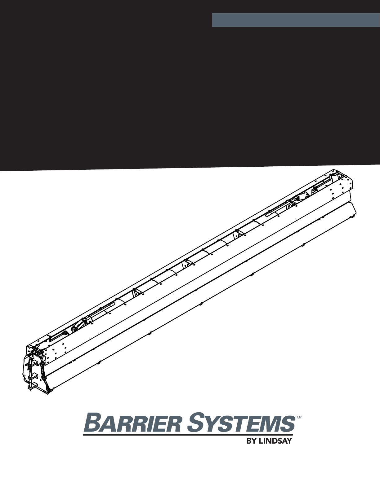
ARMORGUARD® BARRIER
INTRODUCTION
The ArmorGuard Barrier has been fully tested in
accordance with the evaluation parameters contained
in NCHRP Report 350 (Test Level 2 and 3).The system is
a heavily reinforced steel barrier that was designed to
oer a practical solution for including positive barrier
separation in short-term construction work zones and
controlled access points on long term construction
projects.
The system is ideal for locations where safety and
barrier portability are paramount.Freestanding barrier
sections come in 8.5 meter (28 ft) lengths and multiple
sections can be quickly interlocked to form a portable
barrier wall in minutes.
Individual links or multiple connected sections can be
raised onto wheels with a manual jack. No electrical
power or sophisticated control systems are required.
The barrier can be easily deployed or repositioned
by hand or with a vehicle to positively separate and
protect both workers and motorists. You can easily
create a portable crashworthy barrier for work zones
with controlled access for vehicles and equipment.
The system can be deployed on a level or sloped (≤8 %)
smooth surface (concrete or asphalt pavement) or on
any relatively smooth surface (gravel on base) capable
of supporting the weight of the system.
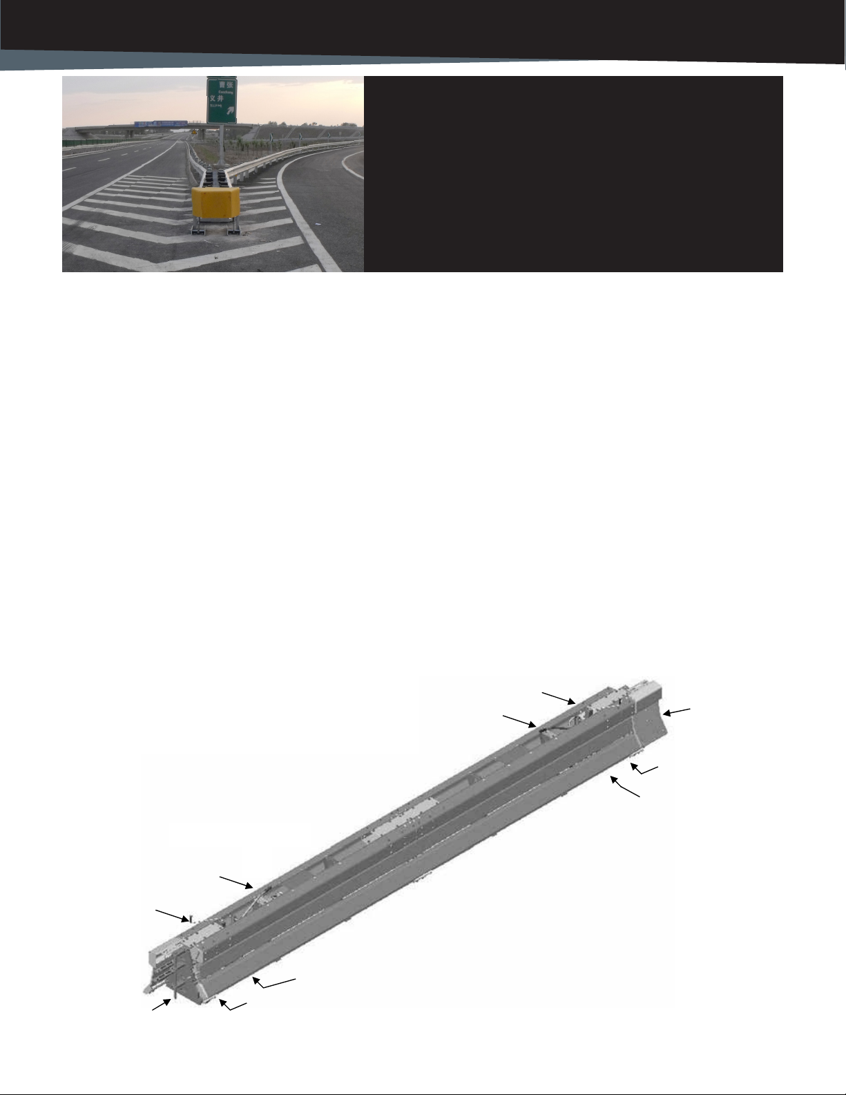
SYSTEM OVERVIEW
Longitudinal barriers are highway safety devices whose
primary functions are to prevent vehicular penetration
and to safely redirect errant vehicles away from
roadside or median hazards. The ArmorGuard Barrier is
used as a portable longitudinal barrier. Each 8.5 meter
(28 ft) section is hinged at both ends and a manual jack
system to raise the gate section onto wheels. A steering
wheel is located on both ends of each barrier section.
The steering wheel is attached to a tiller handle located
at the top of the barrier that can be used to steer the
link section in virtually any direction.
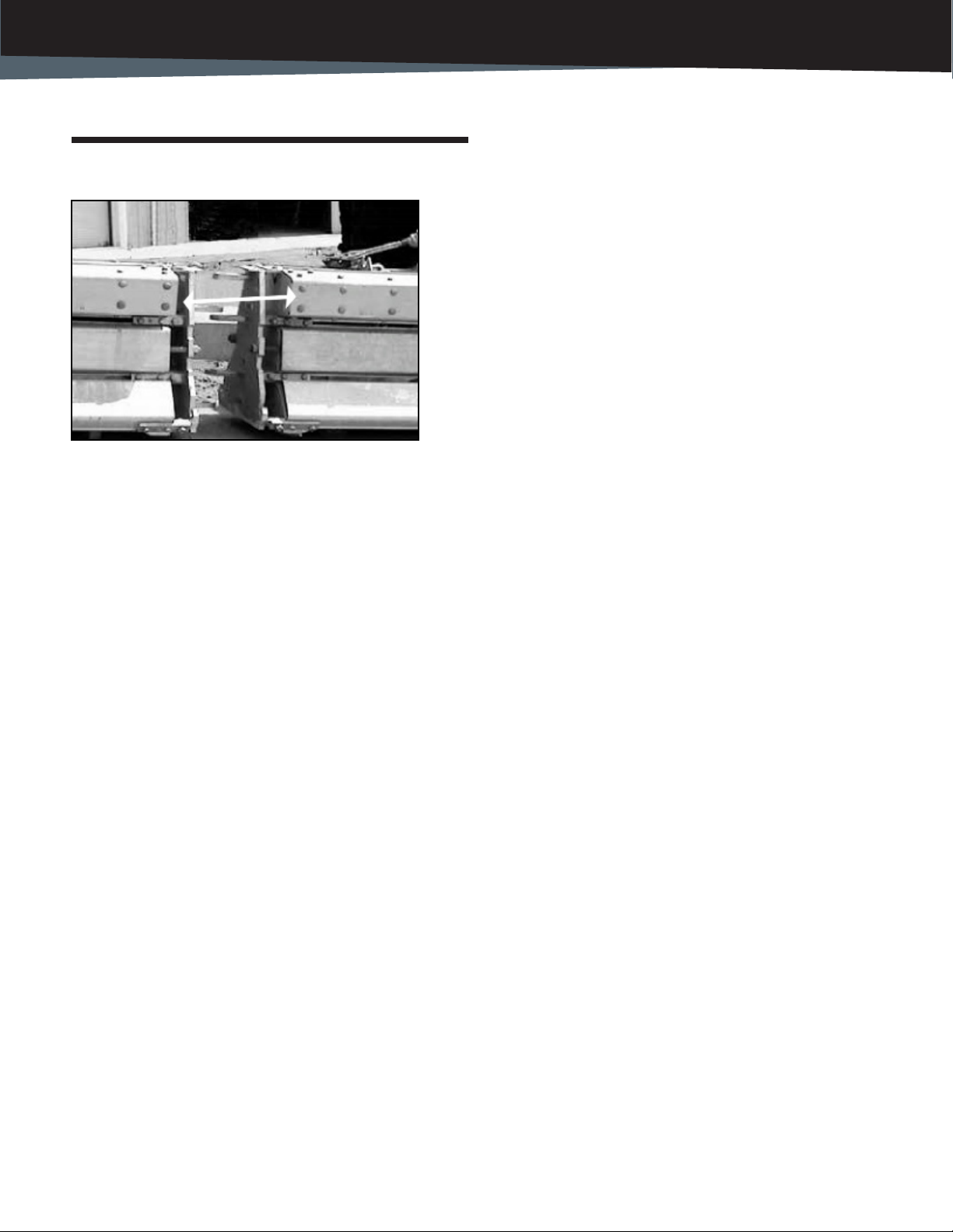
With the tillers pointed in the same direction multiple
sections of barrier can be simultaneously moved.
Large systems of barrier can be quickly moved to a new
lane position or to the curb or median using a vehicle
equipped with a special roller device (see Figure 16).The
system is approximately 700 mm (28”) wide, 830mm
(33“) high and 8.5 meters (28 ft) in length. The system
can be easily and quickly deployed or stored without
expensive electrical power supplies or sophisticated
control systems.
REQUIRED TOOLS
ArmorGuard Barrier sections are delivered to the jobsite
fully assembled and ready for service. No assembly is
required.
Manually Lifting a Section:
• The manual lifting system allows a section to
belifted with NO tools.
For General Operations:
• Truck mounted wheel assembly (for lateralmoves
with a vehicle)
• Come-along (for steep slope operations)
• Chain and clevis (for loading and unloading)
• Pry/construction bar
BEFORE INSTALLATION
Placement and use of the ArmorGuard Barrier should
be accomplished in accordance with the guidelines and
recommendations set forth in the “AASHTO” Roadside
Design Guide,”FHWA memoranda and other state and
local standards for longitudinal barrier.
The system is a highly engineered safety device made
up of a relatively small number of parts. Before starting
use of the system, become familiar with the basic
elements that make up the system.
Before beginning the use of the system, check
the packing list to be certain that all of the system
components were included in the shipment. If any
parts are found to be missing or damaged call the
Lindsay Transportation Solutions Customer Service
Departmentat (888) 800-3691 (U.S. toll free) or (707)
374-6800.
Barrier Systems by Lindsay +1 (888) 800-3691 (U.S. toll free or +1 (402) 829-6800 - ECN 60881 Barrier Systems by Lindsay +1 (888) 800-3691 (U.S. toll free or +1 (402) 829-6800 - ECN 60881
6
INSTALLATION AND MAINTENANCE MANUAL
Deploying ArmorGuard Barrier at a Job Site
Picking up a section
Figure 1. Use the holes located in the tops of the inboard
diaphragms as two lifting points. Lift with a hook or clevis and a
suitable cable or chain. Follow OSHA guidelines for safe forklift
operation.
Figure 2. Use a crane, tractor or forklift to move the sections from the
transport vehicle or trailer onto the job site.
NOTE: Each 8.5 meter section weighs approximately
3000 lbs (1500 kg). While moving, keep your feet clear
and never stand under a lifted section. Personnel should
stand to the side and guide the section into place. Remain
in control of the section being lifted at all times.
Do not pick up sections with a forklift as damage may
occur to the bottom panels from the forks.
Failure to safely secure and or control a section could
result in damage to the section or equipment as well as
bodily injury or death. Follow OSHA guidelines for the
safe fork lift operation.
Operational Instructions
A section can be lifted onto its wheels for storage or
deployment by a manual jacking system.
Manual Jacking System
To manually raise a section, locate the crank on the
end of a section (Figure 3). Remove the crank from its
cradle and simply rotate the crank clockwise to raise the
system or counterclockwise to lower the section back
to the ground. (Both ends must be in the fully raised
position before moving.)
Figure 3. Manually jacking a section
To avoid damage to system components, caution
should be taken that each wheel assembly (hand
jack) is fully deployed during moving operations and
fully retracted when in use.
Barrier Systems by Lindsay +1 (888) 800-3691 (U.S. toll free or +1 (402) 829-6800 - ECN 60881 7
ARMORGUARD® BARRIER
Moving the System with Personnel
After the section has been lifted and locked in the up
position it can be moved with human power or vehicle
power. The rst step in any move is to position the tillers
so that the section will move in the desired direction.
Figure 4. The Steering Wheels are connected to the Tiller Handle
located on the top of each end of the barrier. Remove the Tiller
Handle from its cradle and use it to position the steering wheels in
the desired direction of travel.
NOTE: Failure to follow this procedure could cause
damage to the steering wheels. Never force a section
in a direction other than in the steering wheel
direction.
Figure 5. Relocate the section, or in this case Multi-section (56’) to
the desired position. Typically two people can easily control and
move a single link section (28’) and 3 people are typically used to
move a multi-section (56’) as shown above.
Tiller Handle
Steering Direction
Figure 6. (QUICK TIP) If a section is dicult to get started moving, use
the Hinge Pin as a lever to start the section moving.
Figure 7. There are two dierent ends on a barrier section. Be sure
that you have a Lower hinge matched with an Upper hinge section
before installing the hinge pin.
Figure 8. When all of the holes of the two section hinges are aligned,
install the hinge pin. The pin must be fully installed.
Barrier Systems by Lindsay +1 (888) 800-3691 (U.S. toll free or +1 (402) 829-6800 - ECN 60881 Barrier Systems by Lindsay +1 (888) 800-3691 (U.S. toll free or +1 (402) 829-6800 - ECN 60881
8
INSTALLATION AND MAINTENANCE MANUAL
Figure 9: Install the hinge covers by rst dropping the rod located
on the inside bottom of the cover in the slots located on each of the
hinge bases. Rotate the cover up to the closed position and install
the two keeper pins through the top.
Figure 10: The hinge covers will stay upright and opened after the
cover is installed as instructed above.
Figure 11: Rotate the cover up to the closed position and install the
two keeper pins through the top as shown below.
The barrier section is now ready to be lowered on to the
ground and put into service. Depending on how the section
was raised, either activate the Air Control Panel to lower the
section or hand jack the section back to the down position.
CAUTION: Keep feet clear from the edge of the section
when lowering.
NOTE: For proper operation all hinge pins and hinge
covers must be installed and each section must be FULLY
lowered so that the section rests on the ground and not
on the wheels.
Moving Barrier with a Vehicle
BSI manufactures a truck mounted barrier push roller
adapter assembly that can be easily attached to a
standard pickup. Using a vehicle, large sections of
barrier can be moved quickly and safely.
Figure 12. The push rollers move the barrier sections without
causing damage.
Figure 13. To deploy a barrier wall that is stored against a curb,
move the end of the barrier out so that the truck can gain access.
Slot Slot
Barrier Systems by Lindsay +1 (888) 800-3691 (U.S. toll free or +1 (402) 829-6800 - ECN 60881 9
ARMORGUARD® BARRIER
Figure 14: Push the barrier over with the vehicle as you drive along
the side of the barrier. The tiller handles must be pointed in the
direction of desired movement.
Figure 15: As the wall is being repositioned personnel lower each
section at its nal deployment or storage position.
Relocating Sections with a Vehicle
A pickup can be used to pull large sections of barrier
either at an angle or straight.
Figure 16. Attach the length of link barrier to a truck using a chain or
a hinge pin as show above.
Figure 17. Pull the barrier straight or at an angle. For an angled move,
all of the steering wheels (using the tiller handle) must be positioned
in the desired direction. Always use caution when towing large
sections of barrier.
Barrier Systems by Lindsay +1 (888) 800-3691 (U.S. toll free or +1 (402) 829-6800 - ECN 60881 Barrier Systems by Lindsay +1 (888) 800-3691 (U.S. toll free or +1 (402) 829-6800 - ECN 60881
10
INSTALLATION AND MAINTENANCE MANUAL
Using AGB on Uneven Surfaces
A pickup can be used to pull large sections of barrier
either at an angle or straight.
Figure 16. Use a winch or a “come along”as shown above to bring
two sections together on a slope so that the hinge pin can be
removed on installed.
Use caution when moving sections on a slope or on
the crown of a roadway. Barrier sections roll easily and
control of the sections must be maintained at all times.
The steering wheel can be used as a break to stop the
movement of a section on a slope when the wheel is
positioned perpendicular to the direction of the slope.
Barrier Systems by Lindsay +1 (888) 800-3691 (U.S. toll free or +1 (402) 829-6800 - ECN 60881 11
ARMORGUARD® BARRIER
ArmorGuard Barrier Operation on Sloped
Surfaces
Lindsay Transportation Solutions Sales and Services, Inc (888) 800-3691 [U.S. toll free] or +1 (707) 374-6800 Lindsay Transportation Solutions Sales and Services, Inc (888) 800-3691 [U.S. toll free] or +1 (707) 374-6800
12
ArmorGuard Barrier Operation on Sloped
Surfaces
The ArmorGuard Barrier is designed to be placed on
surfaces (that are in compliance with that stated in the
Product Specications) with slopes up to 8% (<5°).
The AGB shall be capable of performing in compli-
ance with the requirements for a longitudinal barrier in
the National Cooperative Highway Research Program
Report 350 (NCHRP 350), Test
Level 3, when installed in this condition. However, if
the AGB is to be installed on a sloped surface, provi-
sions need to be made to always ensure that there is
positive control of the system in the opening and clos-
ing operations. Lack of positive control could lead
to potential injury of operating personnel or adjacent
motorists if the system were to swing open or closed
in an uncontrolled manner.
To ensure that the system is positively controlled, a
rope, or ”tether line,” with a tensile capacity of at least
2000 pounds (900 kg) should be connected between
the removable AGB element and the system. Antici-
pated lateral loading from an 8% slope should be less
than 200 pounds (90 kg). Once the “tether line” is
rmly connected, remove the hinge pin and then raise
the system onto the wheels. The system should be
raised slowly and only a small amount (to just come
onto the wheels) to keep positive. If the barrier starts
to move, tilt it slightly so that the rubber pads act as
a friction brake and then slowly play line out to guide
the section in the desired location.
Typically, the tether line should be attached between
the “uphill” elements, since the moveable element will
have a tendency to roll downhill when the system is
raised onto the wheels.
The same tether line system can be used to pull the
system back into position when it is being closed. Do
not disconnect the tether line until the hinge pins are
in the locked position, the barrier is lowered onto the
road surface, and the system is secured.
If it is necessary to disconnect the tether line without
the hinge pins being locked in place, lower the barrier
to put the full weight of the section onto the rubber
pads resting on the road surface and with the wheels
not touching the road surface.
ArmorGuard Barrier Towing Specications
The ArmorGuard Barrier can be rolled manually around a
job site over any solid ground that can support its weight.
Deep troughs or potholes are not acceptable since the
wheels will drop into the depression and the barrier will
high center.
The ArmorGuard Barrier can be towed short distances at
low speeds. Care must be taken to ensure safety, reliabili-
ty, and to limit damage and wear to the system. A smooth,
at road surface is necessary for longitudinal transfers
longer than the length of the system being moved, (usually
400-1000 feet). If any of the following specications can-
not be met, the system must be alternatively transported.
Surface Conditions for Towing:
•Smooth surface capable of supporting the weight
of the system
•No potholes, rumble strips, or raised pavement
markers
•Less than 2 degree cross slope
It is acceptable to tow a system across a rumble strip
or raised pavement markers as long as the speed is
less than 1 MPH.
Towing Control:
• A pivoting or exible attachment should be used to
connect the tow vehicle to the Link series (exam-
ple: chain, strap, or link bars). This limits exces-
sive wear to the front wheel assemblies.
• The rst (3) tiller positions behind the tow vehicle
must be manually steered as the tow vehicle
turns to minimize scrubbing.
•Proper tethering or restraints should be used when
navigating cross slopes or descents to ensure
control at all times.
•Adequate personnel must be utilized to control the
system while under tow. The system requires
monitoring and steering corrections at various til-
ler locations in the series.
ARMORGUARD®BARRIER
ArmorGuard Barrier Towing Specications
Barrier Systems by Lindsay +1 (888) 800-3691 (U.S. toll free or +1 (402) 829-6800 - ECN 60881 Barrier Systems by Lindsay +1 (888) 800-3691 (U.S. toll free or +1 (402) 829-6800 - ECN 60881
12
INSTALLATION AND MAINTENANCE MANUAL
Lindsay Transportation Solutions Sales and Services, Inc (888) 800-3691 [U.S. toll free] or +1 (707) 374-6800 13
DISTANCE (MILES)
3
2
1
0
TOWING SPEED VS. DISTANCE
TOWING SPEED
0 1 2 3
SPEED (MPH)
Towing Speed:
•Towing speed is never to exceed 3 mph –
Speeds greater than 3 mph may cause severe
wheel damage
•For longer distance transfers, the speed limit
reduces (see Chart)
o1 mile transfer ≤3 mph maximum
o2 mile transfer ≤2 mph maximum
o3 mile transfer ≤1 mph maximum
•Towing distance should not exceed 3 miles
Limitations and Warnings
ArmorGuard Barrier has been rigorously tested and
evaluated per the recommendations in the NCHRP Report
350 Guidelines for Test Level 3 (TL-3) longitudinal barri-
ers. The impact conditions recommended in NCHRP 350
are intended to address typical in-service collisions.
When ArmorGuard Barrier is properly installed and main-
tained, the system is capable of redirecting impacting ve-
hicles in a predictable and safe manner under the NCHRP
350 impact conditions of:
Vehicles: Pickup (2000P) and small car (820C)
Mass: 4400 lbs. (2000 kg) & 1800 lbs. (820 kg)
Speed: 62 mph (100 km/hr)
Angle: 25 degrees for pickup and 20 degrees for
small car
Vehicle impacts that vary from the NCHRP 350 impact
conditions described for longitudinal barriers may result
in signicantly different results than those experienced in
testing. Vehicle impact characteristics different than or
in excess of those encountered in NCHRP 350 testing
(speed and angle) may result in system performance that
may not meet the NCHRP 350 evaluation criteria.
INSTALLATION AND MAINTENANCE MANUAL
Relocating Sections with a Vehicle
Barrier Systems by Lindsay +1 (888) 800-3691 (U.S. toll free or +1 (402) 829-6800 - ECN 60881 13
ARMORGUARD® BARRIER
Periodic Maintenance
The ArmorGuard Barrier System has been designed to
minimize the need for periodic maintenance. The only
periodic maintenance items that need to be addressed are as
follows:
• Apply grease (Chevron EP NLGI 2 grease or equivalent) to
the zerk ttings on the caster wheels at least annually.
General Inspection and Maintenance
Drive-by Inspection
Drive-by type inspections should be performed at least
monthly. The purpose of the drive-by inspection is to
observe for the following characteristics:
• Any evidence of vehicle impacts.
• Structural damage.
• Loose or out of place components.
• Excessive debris build-up that would not allow the
system to be operated.
If any of these conditions are observed, a walk-up inspection
is required.
Walk-up Inspections
Walk-up inspections should be conducted at least annually
and whenever deemed appropriate from a drive-by
inspection. A walk-up inspection should consist of the
following items:
• Structural components – Conduct an inspection of all
structural assemblies to ensure that all components are
structurally sound, properly connected and there are no
loose fasteners or damaged components. The hinge pins
should be in position and free to move and the hinge
covers properly tted and connected. Any components
observed to be nonconforming to the manufacturer’s
drawings should be replaced or repaired.
• Operating systems – Raise, hold, and lower the system
in accordance with the operating instructions and
ensure that the hinge covers, hinge pins, casters and
other functional components operate in the proper
manner. Any components observed to be decient
should be repaired or replaced in accordance with the
manufacturer’s instructions.
• General cleaning – The area around and within the
internal and external operating area should be kept free
of debris that could aect either the impact performance
or restrict the ability to open or close the system when
needed.
For additional information regarding this product, please
contact:
Lindsay Transportation Solutions
Sales and Service, Inc.
180 River Road
Rio Vista, CA 94571
U.S. Toll Free (888) 800-3691
Phone: (402) 829-6800
Fax: (707) 374-6801
Barrier Systems by Lindsay
18135 Burke St., Elkhorn, NE 68022 • U.S. Toll Free: (866) 404-5049 • www.lindsaytransportationsolutions.com
Installation manual for the ArmorGuard system is subject to change without notice to reect improvements and upgrades.
Please contact Barrier Systems by Lindsay to conrm that you are using the most current installation manual and instructions.
Additional information is available from Barrier Systems by Lindsay. © Barrier Systems by Lindsay
DISTRIBUTED BY:
ARMORGUARD® BARRIER

Other Lindsay Control System manuals

Lindsay FIRLDNET GSM CELLULAR RTU User manual

Lindsay

Lindsay FIRLDNET GSM CELLULAR RTU User manual

Lindsay Universal TAU-II User manual

Lindsay

Lindsay Universal TAU-II User manual

Lindsay Barrier Systems X-LITE User manual

Lindsay

Lindsay Barrier Systems X-LITE User manual

Popular Control System manuals by other brands

Woodward Vertex-Pro Installation/Hardware Manual

Woodward

Woodward Vertex-Pro Installation/Hardware Manual

Norac UC4 Total Control installation manual

Norac

Norac UC4 Total Control installation manual

Digitrax Zephyr Express DCS52 manual

Digitrax

Digitrax Zephyr Express DCS52 manual

Honeywell NOTIFIER ACS Series manual

Honeywell

Honeywell NOTIFIER ACS Series manual

Sorotec MINI Control Assembly instruction

Sorotec

Sorotec MINI Control Assembly instruction

Roger MCX16-UZ installation manual

Roger

Roger MCX16-UZ installation manual

Allen-Bradley ControlLogix 1756-CNB user manual

Allen-Bradley

Allen-Bradley ControlLogix 1756-CNB user manual

DEWESOFT IOLITE Series Technical reference manual

DEWESOFT

DEWESOFT IOLITE Series Technical reference manual

Pepperl+Fuchs Bebco EPS 6100-MP-EX Series instruction manual

Pepperl+Fuchs

Pepperl+Fuchs Bebco EPS 6100-MP-EX Series instruction manual

FMS RTM X42.CC operating manual

FMS

FMS RTM X42.CC operating manual

Balboa Deluxe Digital Control owner's manual

Balboa

Balboa Deluxe Digital Control owner's manual

Hytek FC20 Technical data

Hytek

Hytek FC20 Technical data

ATEN VK0200TTK user manual

ATEN

ATEN VK0200TTK user manual

U.S. Security Solutions CA601 user manual

U.S. Security Solutions

U.S. Security Solutions CA601 user manual

eqss OverWatch Sinoboom RD-RT Series installation manual

eqss

eqss OverWatch Sinoboom RD-RT Series installation manual

Johnson Controls FC-2000 introduction

Johnson Controls

Johnson Controls FC-2000 introduction

IN-COMMAND JRVCS2 Installation and operation manual

IN-COMMAND

IN-COMMAND JRVCS2 Installation and operation manual

YASKAWA CP 341 manual

YASKAWA

YASKAWA CP 341 manual

manuals.online logo
manuals.online logoBrands
  • About & Mission
  • Contact us
  • Privacy Policy
  • Terms and Conditions

Copyright 2025 Manuals.Online. All Rights Reserved.