WEIHONG NK280B User manual

NK280B Integrated CNC System
Manufacturers’ Manual
1st Edition
Weihong Electronic Technology Co., Ltd.
(Exclusive to 3C industry)

The copyright of this manual belongs to Weihong Electronic Technology Co., Ltd. (hereinafter referred to as
Weihong Company). This manual and any image, table, data or other information contained in this manual may
not be reproduced, transferred, or translated without any prior written permission of Weihong Company.
The information contained in this manual is constantly being updated. You can login to the official website of
Weihong Company www.weihong.com.cn/en/to download the latest PDF edition for free.

Preface「I」
Preface
About This manual
This manual is intended for manufacturers. If you use Weihong CNC system for the first time, it is
suggested to read through this manual. If not, however, you can search for the desired information via
the contents.
Section
Contents
Preface
It introduces applicable product model, contact information and
revision history.
Get Started
It introduces the hardware components, NK280B operational
panel and software.
Basic Commissioning
It introduces commissioning for the machine tool and driver before
machining.
Operation
It introduces main operations involved during machining.
System Maintenance
It introduces operations about the registration and update of
system and software.
NK280B Parameter Reference
It introduces parameters related to main and frequently-used
operations.
Software License Agreement
It is about software license agreement.
Applicable Product Model
This manual is applicable to NK280B integrated CNC system, exclusive to 3C industry. Refer to the table
below for details.
Product Model
Remarks
NK280B integrated CNC
system
Abbreviated as NK280B, this system supports bus control system.
Functions of NK280B integrated CNC system differ according to
business line and application industry. This manufacturers' manual
is applicable to customers of WEIHONG 3C business line.
If there is no special explanation, all images belong to general
three-axis software.

Preface「II」
Contact Us
You can contact us by the following info for technical support and pre-sales / after-sales service:
Company Name: Weihong Electronic Technology Co., Ltd.
HeadquartersAddress: No.1590, Huhang Rd., Fengxian, Shanghai, PRC 201400
Tel: +86-21-33587550
Fax: +86-21-33587519
Website: www.weihong.com.cn/en/
Revision History
You can refer to the following table for the revision records of each edition.
Date
Edition
Revision
2018.01
R1
This manual is written according to the following versions:
BOOT version: V1.3.3.
General Three-axis software:
NK280B_通用三轴_8.8.4_1709291646.
General Double Z software:
NK280B_通用双 Z_9.0.0_1712201005.weihong

Contents
Getting Started............................................................................................ 5
Hardware Components..................................................................................................................................................5
NK280B Operational Panel...........................................................................................................................................5
LED Display................................................................................................................................................................ 6
Main Function Access Buttons...........................................................................................................................7
Alpha-numeric Keypad.......................................................................................................................................... 7
Buttons for Mode Switch..................................................................................................................................... 9
ESTOP Switch.............................................................................................................................................................9
Buttons for Auxiliary Functions..........................................................................................................................9
Override Switch......................................................................................................................................................10
Buttons for Movement Control....................................................................................................................... 10
Operational Buttons.............................................................................................................................................11
Interface on the Back..........................................................................................................................................11
Software............................................................................................................................................................................ 11
Basic Commissioning................................................................................ 12
Switch Operating Language...................................................................................................................................... 12
Execute Auto Adjustment...........................................................................................................................................13
Set Station Address for Driver.........................................................................................................................13
Set Driver Parameters..........................................................................................................................................16
Execute Auto Adjustment.................................................................................................................................. 17
Check and Modify Port...............................................................................................................................................21
Adjust Axis Direction....................................................................................................................................................22
Operation....................................................................................................23
Execute Warm-up and Trial Run..............................................................................................................................24
Manually Move Machine Tool.................................................................................................................................. 24
Switch Software Configuration.................................................................................................................................25
Return to Machine Origin..........................................................................................................................................25
Return to Machine Origin in Incremental Mode.......................................................................................25
Set Absolute Datum.............................................................................................................................................26
Select Z-axis.................................................................................................................................................................... 26
Calibrate Tool.................................................................................................................................................................. 27
Execute Fixed Calibration...................................................................................................................................27
Execute First and Exchange Calibration....................................................................................................... 28
Set Tool Number........................................................................................................................................................... 28
Set Workpiece Coordinate.........................................................................................................................................28
Set WCS Origin by Centering.......................................................................................................................... 29

Set WCS Origin by Clearing............................................................................................................................. 29
Set Workpiece Offset...........................................................................................................................................30
Set Public Offset....................................................................................................................................................30
Back up Coordinate..............................................................................................................................................30
Manage Technics........................................................................................................................................................... 31
Execute Arraying....................................................................................................................................................31
Compensate Workpiece......................................................................................................................................31
Compensate Screw Error....................................................................................................................................32
Manage Tool Life...................................................................................................................................................32
Compensate Tool...................................................................................................................................................33
Connect Network...........................................................................................................................................................33
Manually Set IP Address.................................................................................................................................... 34
Automatically Set IP Address........................................................................................................................... 34
Modify Device Information............................................................................................................................... 34
Verify Network Connection...............................................................................................................................35
Manage Program Files................................................................................................................................................ 35
Access Local Files..................................................................................................................................................36
Access USB Program Files................................................................................................................................. 36
Access NK280B Program Files from Computer......................................................................................... 36
Access Network Files........................................................................................................................................... 37
Run Program Wizard........................................................................................................................................... 37
Set Parameters................................................................................................................................................................38
Modify Parameters............................................................................................................................................... 38
Back Up Parameters.............................................................................................................................................39
Simulate.............................................................................................................................................................................40
Run Program................................................................................................................................................................... 41
Execute Auto Run................................................................................................................................................. 41
Execute Single Block............................................................................................................................................ 41
Use Handwheel Guide.........................................................................................................................................41
Enable Selective Machining.............................................................................................................................. 41
Adjust Track View..........................................................................................................................................................42
Return to Workpiece Origin......................................................................................................................................43
Return to Fixed Point...................................................................................................................................................43
Execute MDI.................................................................................................................................................................... 43
Check Statistics Information......................................................................................................................................44
Check Logs.......................................................................................................................................................................44
System Maintenance.................................................................................45
Register Software and Driver....................................................................................................................................45
Update FPGA...................................................................................................................................................................46
Delete Temporary Files................................................................................................................................................46
Update Software to Latest Version.........................................................................................................................46

Update Mirror Image...................................................................................................................................................46
Install Software...............................................................................................................................................................47
Update BOOT Interface...............................................................................................................................................47
NK280B Parameter Reference................................................................. 48
Parameter for Axis Direction.....................................................................................................................................48
Driver Parameters for Auto Adjustment...............................................................................................................48
Parameters for Encoder.............................................................................................................................................. 49
Parameters for Handwheel Operation...................................................................................................................50
Parameters for Workbench Range..........................................................................................................................50
Parameters for Prompt................................................................................................................................................50
Parameters for QEC...................................................................................................................................................... 51
Parameters for Tool Compensation........................................................................................................................52
Parameters for Tool Calibration...............................................................................................................................52
Parameters for Actions after Program End......................................................................................................... 53


Getting Started
Getting Started
Consisting of the hardware and the software, NK280B integrated CNC system can be used for
tapping and drilling, engraving and milling, etc.
Functions of NK280B integrated CNC system differ according to business line and application
industry. Note that this manufacturers' manual is applicable to customers of WEIHONG 3C
business line.
Hardware Components
• NK280B host
• Lambda 5M controller
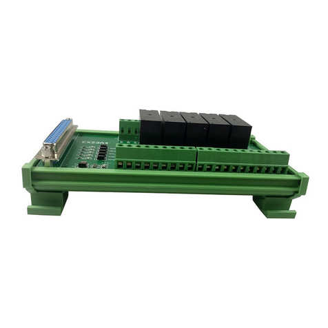
• EX31A1 extended terminal board
• YASKAWA Σ5 / YASKAWA Σ7 / WISE bus-type servo driver
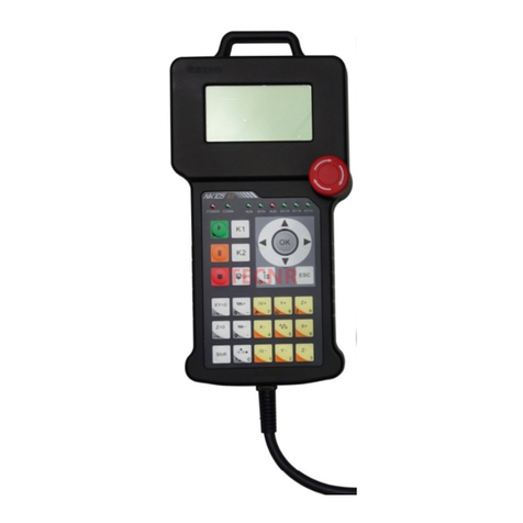
• NK-MPG-06 handwheel (optional)
• DB9M/F cable, M-Ⅱ bus-type cable
NK280B Operational Panel
Before operation, you need to know about hardware components of NK280B integrated CNC
system.
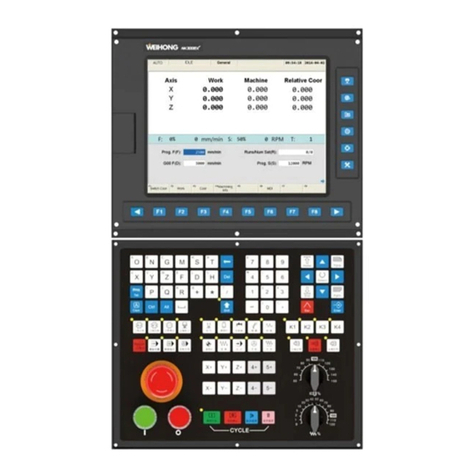
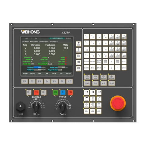
See figure below for NK280B operational panel.
Knowing about NK280B front operational panel.
1LED display
2Main function access buttons
5

Getting Started
3Alpha-numeric keypad
4Buttons for mode switching
5Emergency stop button (E-stop)
6Buttons for auxiliary functions
7Feed override switch
8Spindle override switch
9USB slot
10 Buttons for movement control
11 F1~F7
LED Display
LED display shows different interactive operational interfaces, namely the GUIs.
See figure below for outlines of the GUIs.
(1)
(2)
(3)
(8)
(6)
(7)
(4)
(5)
Outline
1: It shows the current operational mode, including Auto, Jog, Stepping, REF, etc.
2: It shows the current working state of the machine tool, including Idle, Running, ESTOP
(Emergency Stop).
3: It shows name of current program file.
4: It shows running time.
5: It shows information such as working progress or alarms.
6: It shows menus.
7: It shows child interfaces of each main function access button.
6

Getting Started
8: It shows F1~F7 buttons on different GUIs.
Shortcut Keys
You can use shortcuts to execute actions.
Press B to open Motion Trace interface.
Press arrow keys (↑, ↓, ←, →) to select setting items.
Main Function Access Buttons
Button Remark
It contains four child interfaces: Coor-Manual, Motion Trace, Cur.
Program and Part Statistic.
You can return to the machine origin, set spindle speed and feedrate,
calibrate the tool, return to the fixed point, etc.
F1~F7 buttons differ in different operating mode.
It contains four child interfaces: Coor- Manage, Centering, User Code
Input and Technics Management.
You can set the workpiece offset and public offset, make tool
compensation and screw error compensation, etc.
It contains three child interfaces: Local Program, USB File, Prog Wizard.
You can load the program, edit the program or set up the program
wizard.
It contains four child interfaces: Machine Param, Param Backup, Coor
Backup, Driver Param.
You can modify parameter settings and execute auto adjustment.
It contains four child interfaces: Port, Log, System Info and Data
Collect.
You can set the IO ports, check logs and register the system, etc.
Alpha-numeric Keypad
See figure below for alpha-numeric keypad on the operational panel.
7

Getting Started
How to use:
• Directly press the button to enter the alphabet on the right-lower part.
• Press Shift + alphabet button to enter the alphabet on the left-upper part.
• In Manual mode, numeric buttons can be used as axis direction buttons. Only press the axis
direction button, the axis moves at jogging speed; press the axis direction button and rapid
button (“5”) together, the axis moves at rapid jogging speed.
8

Getting Started
Buttons for Mode Switch
See figure below for buttons.
NK280B supports five modes: Auto, Jog, Handle, REF.Point and Stepping mode.
When you want to control the machine movement by handwheel, select Handle mode.
Default override for Handle and Stepping mode is X100.
Select XUD to custom the step length.
ESTOP Switch
When the machine is in danger, press emergency stop button to completely stop the machine.
When the danger is cleared, rotate the switch in clockwise direction to remove emergency alarm.
Buttons for Auxiliary Functions
Buttons are used for directly enabling some frequently-used operations or turning on or off
some ports.
Buttons are:
Make the program run in simulation mode.
Enable handwheel guide function.
Enable the single block function. Once the
button is pressed, one line of code block will
be executed.
Enable or disable the coolant port to turn on
or off the coolant.
Enable or disable the blowing port to start or
stop blowing.
9

Getting Started
Enable or disable the lubricant port to turn on
or off the lubricant.
Enable or disable the port to make the tool
magazine rotate in clockwise direction or stop
the tool magazine.
Enable or disable the port to make the tool
magazine rotate in counter-clockwise direction
or stop the tool magazine.
Enable or disable the port to turn on or off the
light.
K1~K3 buttons are reserved for customization, whose functions can be customized.
Override Switch
It contains two types of override switch:
Adjust feed override from 0~120%.
Adjust spindle override from 50~150%.
Relationship between current speed and override is shown below.
Buttons for Movement Control
It contains buttons for spindle control and program running.
Buttons are:
Start the spindle rotation in clockwise
direction.
10

Getting Started
Stop the spindle rotation.
Start the spindle rotation in counter-clockwise
direction.
Start programming running.
Resume programming running. In case of
power interruption or emergency stop in
machining, if the workpiece origin is secured,
press the button to resume program running
from the exact interrupted position.
Stop program running.
Operational Buttons
F1~F7 buttons below the LED display.
Interface on the Back
Connect to correct component according to the following figure.
Software
At present, the software contains two types, according to active axes.
General Double Z Software
The software is used for machine tools with two worktables and two Z-axis. It contains two types
of configuration according to movement of Z1-axis and Z2-axis.
11

Basic Commissioning
• Linkage configuration: Z1-axis and Z2-axis can be active at the same time.
• Alternative configuration: Only Z1-axis or Z2-axis can be active at one time.
See Select Z-axis for details.
General Three-Axis Software
Use the software for normal machine tools with X-axis, Y-axis and Z-axis.
Functions such as “Axis Selection” and “Set Tool No.” are absent here.
Basic Commissioning
Before machining, you need to conduct commissioning to the tool machine and set motion
control system.
After the system is correctly connected and powered on, you can start commissioning according
to the following steps:
Table 1: Overview of Basic Commissioning Process Before Machining
Step Operation Reference
1 According to driver’s brand used, set station
address and adjust servo gain for the driver.
Execute Auto Adjustment
2 Check port information, detect status and wiring of
machine tool and adjust port polarity.
Check and Modify Port
3 Adjust axis direction. Adjust Axis Direction
4 Return to machine origin. Return to Machine Origin
5 Move machine tool and set related parameters. Modify Parameters
NK280B Parameter
Reference
6 Set workpiece coordinate system (WCS), including
workpiece offset and public offset.
Set Workpiece Coordinate
Commissioning finishes. Wait for machining.
Switch Operating Language
At present, Simplified Chinese and English are available.
To switch operating language in use:
1. Press System > C to open System Info interface.
2. Press F3 to choose target language.
3. Restart the software.
The target language takes effect.
12

Basic Commissioning
Execute Auto Adjustment
Auto adjustment aims to automatically adjust servo gain for servo unit according to the current
status of machine tool, and thus to optimize response.
In NK280B, auto adjustment for X-axis, Y-axis and Z-axis will be executed separately. Auto
adjustment will not be executed until the auto adjustment for last axis is done.
Due to the different brands of drivers, process of auto adjustment differs.
Set Station Address for Driver
Setting station address for driver is the prerequisite of data transmission among control system,
lambda controller and driver.
Set Station Address for YASKAWA Driver
The setting of station address for YASKAWA bus-type driver is done through combined actions
of rotary switch(S2) and toggle switch(S3).
To set station address for YASKAWA driver:
1. Optional: Modify setting of No.3 for S3.
Other numbers of S3 adopt factory settings.
Setting illustration for S3 is as shown in the following table:
No. Illustration Factory Setting
1 Setting for communication speed.
• OFF: 4Mbps (M1)
• ON: 10Mbps (M2)
ON
2 Setting for bytes transmitted.
• OFF: 17 bytes
• ON: 32 bytes
ON
3 Setting for station address.
• OFF: actual address=40H+S2
• ON: actual address=50H+S2
OFF
13

Basic Commissioning
No. Illustration Factory Setting
4 System reservation (unalterable). OFF
2. Rotate S2 to the needed value.
Actual station addresses are as shown in the following table:
S3 No.3 S2 Station Address S3 No.3 S2 Station Address
OFF 0 Invalid ON 0 50H
OFF 1 41H ON 1 51H
OFF 2 42H ON 2 52H
OFF 3 43H ON 3 53H
OFF 4 44H ON 4 54H
OFF 5 45H ON 5 55H
OFF 6 46H ON 6 56H
OFF 7 47H ON 7 57H
OFF 8 48H ON 8 58H
OFF 9 49H ON 9 59H
OFF A 4AH ON A 5AH
OFF B 4BH ON B 5BH
OFF C 4CH ON C 5CH
OFF D 4DH ON D 5DH
OFF E 4EH ON E 5EH
OFF F 4FH ON F 5FH
3. Restart the driver to make the settings effective.
Set Station Address for Wise Driver
The setting of station address for Wise driver is done through the panel in front of the driver.
To set station address for Wise driver:
1. Set the value of driver parameter Pr001 Control Mode Setup to 1.
14

Basic Commissioning
2. Set station address No.
It is suggested to set station address number in order, eg.: X-axis: 1; Y-axis: 2; Z-axis: 3.
When the No. is 0, it means communication function is disabled.
In the same control system, every station address No. is unique.
15

Basic Commissioning
3. Restart the driver.
Set Driver Parameters
To set driver parameters:
1. Press Parameter > =.
Driver Param interface shows.
2. To modify driver parameter, pressing direction key ↑/↓/←/→ > Enter.
Due to different driver brands, setting of parameter differs. Setting value of Driver Type in
software shall prevail.
3. Do one of the following:
Keys Explanation
F1 Add other parameters that do not show.
Note:
Wise driver shows all parameters while YASKAWA driver shows only a part of them.
F2 Delete parameters unnecessary to show on the Driver Param interface.
F3 Restore all parameters to its initial status, that is, all the added parameters will be
invalid.
F4 Restore settings of all parameters to factory settings.
F5 Directly import parameter files from mobile devices like USB flash disk to driver.
Note:
16
Table of contents
Other WEIHONG Control System manuals

WEIHONG
WEIHONG LS1500 User manual

WEIHONG
WEIHONG Ncstudio V15 User manual

WEIHONG
WEIHONG NK200 User manual

WEIHONG
WEIHONG NK300CX User manual

WEIHONG
WEIHONG NK105 G2F User manual

WEIHONG
WEIHONG NCStudio V12 User manual

WEIHONG
WEIHONG NK280 User manual

WEIHONG
WEIHONG PM53B User manual

WEIHONG
WEIHONG NK300CX User manual

WEIHONG
WEIHONG 200 Series User manual
Popular Control System manuals by other brands

Data I/O
Data I/O PSV5000 Operator's manual

Eaton
Eaton COOPER POWER SERIES Installation and operation instructions

Agilent Technologies
Agilent Technologies 7890 GC Preparation checklist

Siemens
Siemens SIMATIC PCS 7 Operation and maintenance

Brivis
Brivis MPS owner's manual

SKF
SKF Multilog On-Line System IMx-M user manual