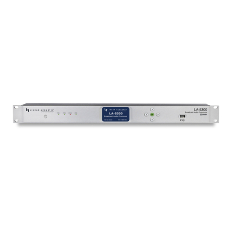
Linear Acoustic LA-5300 User manual

1
Linear Acoustic LA-5300
Broadcast Audio Processor
Preliminary Quick Start Guide
Introduction
The roll-out of ATSC 3.0 presents a unique set of requirements and opportunities for
television broadcasters, including many enhanced audio capabilities. The Linear
Acoustic LA-5300 provides a single 1RU solution for audio loudness control,
upmixing, AC-4 decoding for watermarking, bitstream analysis, and monitoring,
transcoding of Dolby® Digital and Dolby Digital Plus sources to AC-4, as well as
Dolby AC-4 encoding of PCM. As ATSC 3.0 adoption grows, support for additional
features including immersive and object-based audio, interactive consumer control,
personalized audio, and multiple presentations within a single stream will be
incorporated into the LA-5300 via software updates.

2
Hardware
LA-5300 Front Panel
Figure 1: Front panel
The front panel of the LA-5300 includes the following:
•Reset button for restarting the unit from the front panel (1A)
•Four status LEDs indicating the status of each power supply (1B, 1C), the
overall status of the unit (1D), and sync for the reference clock (1E)
•A color LCD display to show status and basic configuration parameters (1F)
•A five-button navigation cluster with Left, Right, Up, and Down arrows plus a
green “OK” button (1G)
•A USB port used for software updates (1H).

3
LA-5300 Rear Panel
Figure 2: Rear panel
The rear panel includes the following connections:
•Two RJ-45 Gigabit Ethernet connections, one for network remote control (2A)
and one for AES67 I/O (2B)
•Two independent 3Gb/s HD/SD-SDI inputs and outputs (2C) on female BNC
connectors
•Quad-Link SDI or MADI I/O (2D) - optional
•Five AES-3 I/O connections (2E) on female BNC connectors
•Parallel GPI/O control port (female DB-15) for five inputs and five outputs (2F)
•Two IEC power inlets for the redundant internal universal auto-ranging power
supplies (2G)

4
Installation and Initial Setup
Installation
LA-5300 is a 1RU product intended to be permanently installed in standard 19 ½”
equipment rack and secured with four standard rack screws. LA-5300 is fan cooled
with air intakes and exhausts located on the side of the unit just behind the front
panel, but whenever possible, it is recommended to leave 1RU of empty space above
and below the unit.
Power
Plug the supplied IEC power cords into the LA-5300 and connect each to different
mains power sources. Remember that while redundant supplies do protect against
the unit losing power in the event of a PSU failure, the loss of mains supply voltage is
a bigger concern. Accordingly, each supply should be fed from a different circuit
equipped with adequate surge protection and fitted with an uninterruptable power
supply (UPS).
Boot Up and Splash Screen
The unit will power up as soon as the power cords are connected, and using the
Reset button (A) is not required on initial startup. The front panel of the unit will
remain dark during most of the boot process but the Status LED (D) will light. Once
the boot process is complete, the Home Screen will appear and the Status LED will
turn green.
Setting IP Addresses
LA-5300 ships with DHCP enabled and will automatically retrieve an IP address
when connected to a network with a DHCP server.
Important!
Both the Control and AES67 connections must be connected to
1000BASE-T (Gigabit) switch ports but should not be connected to a
common network with the same netmask/subnet. If both connections
must be on a common network, make the connection to the AES67 port
and set the values of each Control port field to 0.0.0.0.

5
To set a fixed IP address for the Control port:
•Press the Right button once to show the Information screen and once more to
navigate to the IP Configuration (Control) screen
•Press the Down button to highlight “Edit”
•Press the OK button to highlight “Use DHCP”
•Press the Right button to highlight “Yes”
•Press the Up/Down buttons to select “No”
•Press the Left button to highlight “DHCP” again
•Press the Down button to highlight “Address”
•Press the Right button to move to the first digit of the IP address
•Use the Up/Down buttons to change the value
•Use the Right/Left buttons to select another digit to edit
•When finished editing the Address field, press the Right/Left buttons to
highlight “Address” again
•Press the Down button to navigate to the “Netmask” field, following the
instructions above for entering the value
•When finished editing the Netmask field, press the Right/Left buttons to
highlight “Netmask” again
•Press the Down button to navigate to the “Gateway” field, following the
instructions above for entering the value
•When finished editing the Gateway field, press the Right/Left buttons to
highlight “Gateway” again
•Press the Down button to highlight “Update”
•Verify the information has been entered correctly and press the OK button to
save the new values
•If you notice incorrect information and need to start over, use the Right button
to highlight “Cancel” followed by the OK button
If you are using AES67 I/O, pressing the Right button from the IP Configuration
(Control) screen will bring you to the IP Configuration (AES67) screen. The steps for
configuring this port are identical to those above for the Control port.

6
Connecting to the Web-Based User Interface
No special client software is required to remotely connect to the LA-5300, and the
HTML-5-based GUI is device, operating system, and browser agnostic. We
recommend Google Chrome, Firefox, or Apple Safari. The computer or tablet should
be on the same network and subnet as the LA-5300.
Once both LA-5300 and your computer are connected to your network, enter the IP
address of the LA-5300 in the URL field of your browser. Once connected, the Home
screen will appear.
Figure 3: Home screen
Clicking on the LA-5300 logo (3A) will always bring you back to the Home screen.
To log in to the unit, click the Log In button (3B). Individual user accounts and
passwords will be supported in a future software version.

7
Input and Output Routing
Initial I/O Setup
Once logged in, click on the I/O menu (4A). Choose between SDI/AES-3/MADI or
AES67 inputs and outputs in the Workflow menu (4B). Select between viewing
Program (processed) and Passthrough (unprocessed) routing with the
Program/Passthrough switch (4C).
Figure 4: I/O menu
Routing audio into the LA-5300 is a two-step process. The first step is creating an
input group from the available physical hardware inputs. The second step is
routing the audio from these inputs to the program (processor) input.
Creating an Input Group
Click on your first audio input source (5A) to highlight it, then right click and select
“Create Input Group.” You may enter a custom name for this source in the Label
field (5C) and customize the color of the graphical routing lines (5B).
Click the Save button (5D) to save the configuration or the Cancel button (5E) if
you need to start over without saving your configuration.

8
Figure 5: Creating the input group.
Routing Audio to the Program Input
After saving the input group, it is necessary to first set the priority of the input
source by dragging the input audio lines (6A) and then clicking when the desired
priority level (6B) is highlighted. The LA-5300 will look for audio first on inputs
connected to Priority 1. If no signal is present, it will look to subsequent priorities in
order.
Figure 6: Setting priority.

9
Next, choose input signal type (PCM, DD+, or AC-4) from the Type dropdown menu
(7A).
Figure 7: Input signal type.
To edit or delete a group, highlight then right click on the colored Edit rectangle
(8A).
Figure 8: Editing or deleting input group.
Creating an Output Group
The steps for creating an output group are identical to creating an input group, but
with the Outputs menu.
Routing Audio to the Program Output
Once the first output group has been created and saved, drag the output audio
lines from the group to the desired program output, then click to save.

10
Clock Reference
Setting the Clock Reference
Click on the Clock menu (9A). Use the dropdown menus to choose a Primary
Reference Clock and a Secondary Reference Clock (9C) and, if needed, a VRef
clock source (9E) The status of the selected Primary and Secondary Reference
Clocks is shown to the right of the dropdown menu (9D). The status of the clock is
shown for each input (9B) along with the format, resolution, and frame rate for SDI
sources.
The absence or presence of a signal for each input type is shown in the Input Status
section (9B).
Figure 9: Setting the clock reference.

11
Signal Processing and Encoding
Controls for Dolby® AC-4 encoding, upmixing, Nielsen and Verance watermark
encoding, and monitoring are found in the Program 1 menu.
Input metering (10A) and output metering (10B) for all channels and all I/O is
also located on this page.
Figure 10: Input and output meters.

12
AC-4 Encoding
Click on the AC-4 Encoder dropdown menu (11A). Choose the appropriate
Channel Mode (11B), Frame Rate (11C), Bit Rate (11G), Type (11F), Loudness
Regulation standard (11E), and Language (11D) for your application.
Figure 11: AC-4 encoding.

13
Upmixing
Click on the Upmixing dropdown menu (12B).
Choose the program input format using the Input Format dropdown menu (12C).
By default, it is set to “Auto Detect” so that incoming content that already matches
the desired output format will pass through unaltered, while 2- or 3-channel content
will be automatically upmixed. Unless the channel format of your incoming content
is always the same, we strongly recommend leaving this control set to “Auto Detect”
to avoid unpredictable and unexpected results.
Use the Output Format dropdown menu (12D) to choose the desired channel
format on the output.
If you change any upmixing values and want to save those changes to a custom
preset, click on the Save As button (12E). This configuration can then be recalled by
clicking on the Preset dropdown menu (12A).
Figure 12: Upmixing

14
Nielsen Watermark Encoding
Click on the Nielsen dropdown menu (13C).
Click on the Enable dropdown menu (13B) to enable/disable Nielsen
watermarking. Choose the appropriate process for your application in the Active
Process dropdown menu (13A). Click on the SID, Check Digit, CSID, and/or CBET
Check Digit fields (13D) to enter the specific codes as provided by Nielsen.
Figure 13: Nielsen watermark encoding.

15
Verance Watermark Encoding
Click on the Verance dropdown menu (14C).
Click on the Enable dropdown menu (14B) to enable/disable Verance
watermarking and the Calibrate dropdown menu (14A) to enable/disable the
calibration mode. Click on the Server Code and Interval Code fields (14D) to enter
the specific codes as provided by Verance.
Figure 14: Verance watermark encoding.

16
Monitoring
The LA-5300 includes a built-in AC-4 decoder for confidence monitoring. Click on
the Monitor dropdown menu (15C) to access it.
Click on the Channel Mode dropdown menu (15B) to choose a 5.1-channel output
or a Lo/Ro or Lt/Rt downmix. The Target Reference Level dropdown menu (15A)
sets the decoded monitor output level. The DRC Enable dropdown menu (15 D)
determines whether or not the monitor output obeys the DRC profile metadata from
the incoming AC-4 bitstream.
Figure 15: AC-4 confidence monitoring.

17
User Warnings and Cautions
The installation and service instructions in this manual are for use by qualified
personnel only.
To avoid electric shock, do not perform any servicing other than that contained in
the operating instructions unless you are qualified to do so. Refer all servicing to
qualified personnel
This instrument has an auto-ranging line voltage input. Ensure the power voltage is
within the specified range of 100-240VAC. The ~ symbol, if used, indicates an
alternating current supply.
This symbol, wherever it appears, alerts you to the presence of uninsulated,
dangerous voltage inside the enclosure –voltage which may be sufficient to
constitute a risk of shock.
This symbol, wherever it appears, alerts you to important operating and
maintenance instructions. Read the manual.
CAUTION: HAZARDOUS VOLTAGES
The instrument power supply incorporates an internal fuse. Hazardous voltages
may still be present on some of the primary parts even when the fuse has blown. If
fuse replacement is required, replace fuse only with same type and value for
continued protection against fire.
WARNING:
The product’s power cord is the primary disconnect device. The socket outlet should
be located near the device and easily accessible. The unit should not be located such
that access to the power cord is impaired. If the unit is incorporated into an
equipment rack, an easily accessible safety disconnect device should be included in
the rack design.
To reduce the risk of electrical shock, do not expose this product to rain or moisture.
This unit is for indoor use only.
This equipment requires the free flow of air for adequate cooling. Do not block the
ventilation openings on the rear and sides of the unit. Failure to allow proper
ventilation could damage the unit or create a fire hazard.

18
Do not place the units on a carpet, bedding, or other materials that could interfere
with any panel ventilation openings.
If the equipment is used in a manner not specified by the manufacturer, the
protection provided by the equipment may be impaired.
USA CLASS A COMPUTING DEVICE INFORMATION TO USER WARNING
This equipment generates, uses, and can radiate radio-frequency energy. If it is not
installed and used as directed by this manual, it may cause interference to radio
communication. This equipment complies with the limits for a Class A computing
device, as specified by FCC rules, part 15, subpart j, which are designed to provide
reasonable protection against such interference when this type of equipment is
operated in a commercial environment. Operation of this equipment in a residential
area is likely to cause interference. If it does, the user will be required to eliminate
the interference at the user’s expense. Note: objectionable interference to TV or
radio reception can occur if other devices are connected to this device without the
use of shielded interconnect cables. FCC rules require the use of shielded cables.
CANADA WARNING
This digital apparatus does not exceed the Class A limits for radio noise emissions
set out in the radio interference regulations of the Canadian department of
communications.
Le présent appareil numérique n’émet pas de bruits radioélectriques dépassant les
limites applicables aux appareils numériques (de Class A) prescrites dans le
règlement sur le brouillage radioélectrique édicté par le ministère des
communications du Canada.
CE CONFORMANCE INFORMATION
This device complies with the requirements of the EEC council directives:
•93/68/EEC (CE MARKING)
•73/23/EEC (SAFETY –LOW VOLTAGE DIRECTIVE)
•89/336/EEC (ELECTROMAGNETIC COMPATIBILITY)
Conformity is declared to those standards: EN50081-1, EN50082-1.
Trademarks, Patents, and Licenses
Telos is a trademark of TLS Corp. All other trademarks are the property of their
respective holders.
All versions, claims of compatibility, trademarks, etc. of hardware and software
products not made by The Telos Alliance which are mentioned in this manual or
accompanying material are informational only.

19
The Telos Alliance makes no endorsement of any particular product for any
purpose, nor claims any responsibility for operation or accuracy. We reserve the
right to make improvements or changes in the products described in this manual
which may affect the product specifications, or to revise the manual without notice.
This document and its content are copyrighted by TLS Corporation and may not be
copied, reproduced, or distributed in any form without expressed written
permission.
Patent information can be found at www.TelosAlliance.com/legal
Updates
Telos Infinity Like Gateway’s features and operations are determined largely by
software. The Telos Alliance strives to provide the most stable and feature-rich
software available. We encourage you to check for software updates from time to
time by visiting our website or by contacting us directly.
Feedback
We welcome feedback on any aspect of our products or this manual. In the past,
many good ideas from users have made their way into software revisions or new
products. Please contact us with your comments or suggestions.
We support you…
By Phone/Fax
You may reach our Telos Support Team in emergencies by calling +1 216-622-0247.
For billing questions or other non-emergency technical questions, please call
+1 216-241-7225 between 9:00 AM to 5:00 PM USA Eastern Time, Monday through
Friday.
By Email
By Web
The Telos Web site has a variety of information that may be useful for product
selection and support. The URL is https://www.telosalliance.com/telos
Service
You must contact Telos Alliance before returning any equipment for factory service.
We will need your unit’s serial number, located on the back of the unit.

20
We will issue a return authorization number, which must be written on the exterior
of your shipping container.
Please do not include cables or accessories unless specifically requested by the
Technical Support Engineer. Be sure to adequately insure your shipment for its
replacement value. Packages without proper authorization may be refused.
US customers, please contact Telos Alliance Technical Support at +1-216-622-0247.
All other customers should contact local representative to make arrangements for
service.
Warranty
For the latest Telos Alliance warranty, visit: telosalliance.com/warranty
Register your product
Register your product today to get the full benefits of our warranty, support, and
product updates. telosalliance.com/product-registration/
The Telos Alliance
1241 Superior Ave. Cleveland, OH 44114 USA
+1 (216) 241-7225
Other manuals for LA-5300
1
Table of contents
Other Linear Acoustic Computer Hardware manuals
Popular Computer Hardware manuals by other brands

lefeirc
lefeirc RCbro SPARROW 3-OSD manual

IEI Technology
IEI Technology MPCIE-USB3 Quick installation guide

Whirlwind
Whirlwind PYROBOX Technical specifications

Advantech
Advantech POC-824 user manual

Delta Electronics
Delta Electronics PFC Chokes PFC2811V Series Specifications

Infinion
Infinion TLD5098EP user manual