Linertec LTS-200 Series User manual

TOTAL STATION
LTS-200SERIES
LTS-202N
LTS-205N
On-Board Application
LinertecExpress
INSTRUCTION MANUAL
- 1 -

2

Before using this product, be sure that you have thoroughly read and understood this
instruction manual to ensure proper operation. After reading this manual, be sure to keep in
a convenient place for easy reference.
Exemption clause
1) TI Asahi Co., td. (TIA) shall not be liable for damage caused by Acts of God, fire, alteration or
servicing by unauthorized parties, accident, negligence, misuse, abnormal operating conditions.
2) TIPS shall not be liable for changes or disappearance of data, loss of company profit or
interruption of company operation incurred by the use of this product or malfunction of it.
3) TIPS shall not be liable for damage caused by usage not explained in the instruction manual.
4) TIPS shall not be liable for damage to this product caused by other equipment connected to this
product.
Copyright © 2014 TI Asa i Co., Ltd.
3

DISPLAY AND KEYBOARD.................................................................................................6
Ope ation Key...................................................................................................................6
Function Key.....................................................................................................................7
1. INTRODUCTION.................................................................................................................9
1.1 Int oduction.................................................................................................................9
1.2 Befo e using the Line tecExp ess manual..............................................................10
2. ACCESSING LINERTECEXPRESS...............................................................................12
2.1 How to access Line tecExp ess................................................................................12
2.2 Allocation of each Line tecExp ess Function key..................................................12
2.3 Typical Function keys of Line tecExp ess.............................................................13
3. PROGRAM.........................................................................................................................14
3.1 RDM (Remote Distance Measu ement)..................................................................14
3.1.1 PH INPUT.......................................................................................................15
3.1.2 Refe ence Point-Ta get Distance..................................................................15
3.1.3 Ta get-Ta get Distance.................................................................................15
3.1.4 New Refe ence Point Selection.....................................................................15
3.2 REM...........................................................................................................................16
3.2.1 Gene al Pictu es of Measu ement................................................................16
3.3. VPM..........................................................................................................................17
4. COMMUNICATION..........................................................................................................20
4.1 Text File ead / w ite.................................................................................................22
4.1.1 W iting to Text File.......................................................................................22
4.1.2 Reading f om Text File..................................................................................23
4.1.3 Text File setup................................................................................................26
4.2 Communication with USB........................................................................................28
4.3 DATA TRANSFER...................................................................................................29
4.3.1 Receiving Coo dinate Data...........................................................................29
4.3.2 Sending Data..................................................................................................30
4.3.4 About DataLink DL-01 Softwa e.................................................................34
5.SETUP...................................................................................................................................38
5.1 ADJUST SETTING...............................................................................................38
[3.SHEET CONST]..........................................................................................................38
[4.CRV/REF CORR]........................................................................................................38
[4. COMP AXIS]..............................................................................................................39
to enter..............................................................................................................................39
5.2 ACTION SETTING...............................................................................................39
5.3 UNIT SETTING.....................................................................................................41
5.4 COMMUNICATION SETTING..........................................................................42
5.5 FUNCTION SETTING.........................................................................................42
5.5.1 Language Selection........................................................................................43
5.5.3 Input method selection..................................................................................45
5.5.4 Action Method Selection................................................................................47
5.5.5 Remote method selection...............................................................................47
5.5.6 Compa e method selection............................................................................48
5.5.7 Request aiming selection...............................................................................49
5.5.8 EDM settings selection...................................................................................49
5.5.9 Elevation facto ..............................................................................................50
5.5.10 Duplicate point check..................................................................................51
5.5.11 Meas. Display................................................................................................52
4

5.5.12 Both faces meas............................................................................................53
5.5.13 Save Mode.....................................................................................................53
5.5.14 BACKSIGHT SAVE....................................................................................53
7.MEASURE............................................................................................................................81
7.1 Rectangula Coo dinates..........................................................................................81
7.2 Pola Coo dinates.....................................................................................................82
7.3 Rectangula & Pola Coo dinates...........................................................................84
7.4 IH measu ement........................................................................................................86
8. STAKE OUT.......................................................................................................................89
8.1 Stake Out...................................................................................................................89
8.2 Point to Line..............................................................................................................94
8.3.1 Th ee point...................................................................................................100
8.3.2 Ci cle adius.................................................................................................103
9. FILE MANAGER.............................................................................................................105
9.1 Info mation of the emaining memo y availability.............................................105
9.2 C eation of a new Job.............................................................................................105
9.3 Selection of a Job Name..........................................................................................106
9.4 Deletion of a Job Name...........................................................................................106
9.5 All Clea ...................................................................................................................106
10. VIEW AND EDIT...........................................................................................................107
10.1 C eate the Rectangula Point..............................................................................107
10.2 Edit the Data..........................................................................................................108
10.3 Point Code List......................................................................................................109
10.3.1 Point Code...................................................................................................109
10.3.2 PointCode C eate.......................................................................................111
10.3.3 PointCode Edit...........................................................................................111
11. FREE STATIONING.....................................................................................................112
11.1 Station setup [By Rectangula Coo dinates]......................................................112
11.1.1 Coo dinates, X, Y, Z, IH, and PC input...................................................113
11.1.2 Point selection f om the list.......................................................................114
11.1.3 Station O ientation....................................................................................116
11.1.4 Multiple O ientation..................................................................................117
11.2 Station setup [By Pola Coo dinates]..................................................................118
11.2.1 Point Name input.......................................................................................118
11.2.2 IH, TEMP, PRESS, ppm and PC input...................................................118
11.2.3 Station O ientation....................................................................................119
11.3 FREE STATIONING...........................................................................................120
11.3.1 Stationing by mo e than 3 known points.................................................120
11.3.2 Stationing by two known points..............................................................122
5

All Rights Rese ved
TI Asahi Co., td. is a sole proprietor of the inertecExpress software.
The inertecExpress software and publication or parts thereof, may not be reproduced in any
form, by any method, for any purpose.
TI Asahi Co., td. makes no warranty, expressed or implied, including but not limited to any
implied warranties or merchantability or fitness for a particular purpose, regarding these
materials and makes such materials available.
6

DISPLAY AND KEYBOARD
• Basic display and keyboard of TS-200 series are described below, and the function keys
of inertecExpress are described in “2. ACCESSING INERTECEXPRESS”.
Ope ation Key
Key Desc iption
[POWER] ON/OFF of power supply
[ESC] Returns to previous screen or cancels an operation.
[ILLU] Turns the illumination of the CD display and telescope reticle on
and off.
[ENT] Accepts the selected (highlighted) choice or the displayed screen
value.
[LASER] Displays the laser plummet and the D point screen when you push
the aser key.
[Alphanume ic] At the numerical value screen, the numerical value and the sign “.”
displayed are input. The English characters printed right under
numeric of each key are input.
[HELP] Pressing [l U]+[ESC] key causes a help menu to appear in
BASE MEASURE or causes a help message to appear.
7
Power Supply Key Function Key Illumination Key ESC Key Laser Key
Enter Key
Alphanumeric
and +/- key

Function Key
[ ] F1 Moves the cursor to the left.
[ ] F2 Moves the cursor to the right.
[ ] F3 Moves the cursor up.
[ ] F4 Moves the cursor down.
[ △ ] F1 Goes back five items on the screen.
[ ▽ ] F2 Goes forward five items on the screen.
[RETICLE] F3 Changes the reticle illumination when pressing illumination
key.
[LCD] F4 Changes the CD contrast when pressing illumination key.
[ILLU] F5 Changes the CD illumination when pressing illumination key.
[CLEAR] F5 Clears the figure.
[SELECT] F5 Opens the selection window.
• The Function keys of each inertecExpress function are described in “2. ACCESSING
INERTECEXPRESS” and at each function.
8

Display combination of MODE A o MODE B
Function MODE A MODE B
F1 MEAS DISP
F2 TARGET ANG SET
F3 0 SET HO D
F4 S.FUNC CORR
F5 MODE MODE
• Mode A or Mode B is switched by pressing [F5] [MODE].
ALPHANUMERIC INPUT
The point name etc. is input by the alphanumeric keys as following.
Key
Letter under Key
Lette & figu e o de to input
[0]
[@][.][_][-][:][/][0]
[1]
PQRS
[P][Q][R][S][p][q][r][s][1]
[2]
T V
[T][ ][V][t][u][v][2]
[3]
WXYZ
[W][X][Y][Z][w][x][y][z][3]
[4]
GHI
[G][H][I][g][h][i][4]
[5]
JKL
[J][K][L][j][k][l][5]
[6]
MNO
[M][N][O][m][n][o][6]
[7]
[ ][?][!][_][¯][^][|][&][7]
[8]
ABC
[A][B][C][a][b][c][8]
[9]
DEF
[D][E][F][d][e][f][9]
[.]
[.][,][:][;][#][(][)]
[+/-]
[+][-][*][/][%][=][<][>]
9
1. INTROD CTION
1.1 Introduction
Thank you for your first look at inertecExpress by reading this manual.
The inertecExpress is a user friendly data collection and calculation program for the
INERTEC TS-200 Series Total Stations.
inertecExpress is developed based on PowerTopo, which is known as a versatile on-board
software. The optimum combination of inertecExpress and TS-200 hardware makes
inertecExpress an easy and useful fieldwork tool.
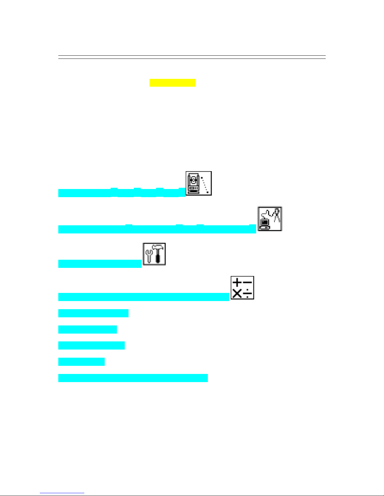
The icon based main menu offers you the following possibilities.
1. PRO: Program(RDM,REM,VPM)
2. I/O: Communication(Text read/write,USB,DATA Transfer)
3. PRE: Preference (Setup)
4. CALC: Calculations (COGO, 2D Surface, Road Design)
5. MEAS: Measurement
6. STAK: Stake out
7. FILE: File manager
8. DATA: Data
9. STATION: Free Station (Backward Intersection)
10

1.2 Befo e using the Line tecExp ess manual
• Memo ies in the inst ument
The TS-200 series incorporates not only the inertecExpress surveying programs as the
Special Function but also File Manager and Data Transfer Programs.
The internal memory of the instrument can store a maximum of 60,000 points of data.
• Relations between the Memo y and each Function
Function Read f om the sto ed data W ite to the sto ed data
Measure SP, BSP SP, BSP, FP (SD)
Stake Out SP, BSP, SOP SP, BSP, SOP, OP
Point to ine SP, BSP, KP1, KP2 SP, BSP, KP1, KP2, OP
Free Stationing Each KP Each KP, SP (CD)
Traverse SP, BSP SP, FP (SD)
VPM SP, BSP, Each KP SP, BSP, Each KP, CP (CD)
Station point: SP Foresight
point: FP Backsight point: BSP Stake Out point: SOP
Known point: KP End point: EP Observation
point: OP Conversion
data: CD
Conversion
point: CP Crossing point: CRP Surveyed data: SD
11

• IH stands for “Instrument Height” and PH stands for “Prism Height”.
• The inertecExpress manual mainly describes the TS-200 special functions, and the
basic operations are described in the (basic) TS-200 manual. Therefore, refer to the
TS-200 basic manual regarding the TS-200 general instrument operations.
The inertecExpress screens vary with the selections of the “Preference”.
The factory default settings of the Preference are shown there. It is also possible to select
“Process type” that takes over the functionality of “ inertecExpress” or “Structure type”
that takes over the functionality of our past product in ”Action Method Selection”.
• The TS-200 series instrument has a Job name of “ INERTEC” and “COGOPoint” as
its default setting. Each data is stored under “ INERTEC” unless another new Job name
is created. When another Job name is created, each data is stored in the new Job name.
• The input range of the X, Y and Z Coordinate is “-99999999.998” - “99999999.998”.
• The input range of the Instrument and Prism height is “-9999.999” - “9999.999”.
• The PC, PointCode ist, is added to the PN, Coordinates X, Y, Z and IH (PH or IH)
and you can input your desired attributes for the point. If you have PointCode ist in the
job named “PointCode ist”, you can easily select one of the PointCode from the list or
edit one of them after pressing [ENT]. Please note, that Point Code, which is saved in the
other job, can not be referred to as a list.
• There are two Coordinates types: Rectangular and Polar.
The RO, VO, DO, TO offset and the remote measurement are possible when you select
the
Rectangular Coordinates.
The RO, DO offset is possible when you select the Polar Coordinates.
• When you measure in EDM SETTINGS of COARSE TRACKING, the TS-200
displays a distance value to two decimal places. However, distance data of polar
coordinates are displayed by EDIT function to three decimal places, and sent, to four
decimal places. So, “0“ or “00” is added to the distance data after the third decimal point
in COARSE TRACKING mode.
For example
Displayed value: 123.45
Displayed by EDIT: 123.450
Sent polar data: 123.4500
• Rectangular coordinates are displayed, stored, and sent to three decimal places even if
in COARSE TRACKING or FINE MEASURE mode.
• You can change the distance measurement mode during measuring operation by
pressing the EDM key at the MEASURE and VPM functions.
• The same Point Name of the plural polar points can be saved.
12

2. ACCESSING LINERTECEXPRESS
2.1 How to access Line tecExp ess
To access the TS-200 Special Functions of the inertecExpress, perform the following
procedures.
Press the [POWER] (ON/OFF) key. The Electronic Vial screeen will comes up.
Press Enter Key or aser Key to proceed to the TS-200 start-up screen.
Then, change to BASE MEASURE screen.
Press [F4] [S.FUNC] to view Functions of inertecExpress screen.
2.2 Allocation of each Line tecExp ess Function key
INVERSE, POINT COORDINATES, INE- INE INTERSECTION functions
CA CU ATION screen is viewed by pressing
[F2] [CA C]. The CA CU ATION consists
of COGO, 2D SURFACE and REM functions.
COGO screen is viewed by selecting 1. COGO and pressing [ENT].
The COGO consists of INVERSE,
POINT COORDINATES,
CIRC E RADIUS,
INE-ARC INTERSECTION,
INE- INE INTERSECTION,
ARC-ARC INTERSECTION,
DISTANCE OFFSET,
POINT DISTANCE OFFSET,
ARC DISTANCE OFFSET,
and functions.
13

2.3 Typical Function keys of Line tecExp ess
Following function keys are typical of inertecExpress and each function key is described for
each function in this Manual.
KEY Desc iption
PAGE Views another function combination.
SE ECT Selects the Character and moves to next input at PN input etc.
ACCEPT Enters the displayed values without new Coordinates value input etc.
INPUT Inputs your desired Horizontal angle.
BSP Views the BSP SETUP screen to input its Coordinates.
SAVE Saves input data.
ME/SAVE Measures and then saves input data.
EDIT Changes the Point Name or Prism Height.
REMOTE Views your aiming point Coordinates.
OFFSET Views the Target Coordinates adding the offset values.
STATION Returns to the STATION POINT SETUP screen.
H. ANG E Returns to the STATION POINT H.ANG E SETUP screen.
IST Views the POINT SE ECTION FROM THE IST screen.
OTHER Views the JOB IST SEARCH screen.
ZOOM A Returns to the original size.
ZOOM IN Magnifies the graphics size.
ZOOM OUT Reduces the graphics size.
DRAW Views the GRAPHICA VIEW screen.
DISP Views point or point & graphic or point & point name or all.
DE ETE Views the POINT DE ETION screen.
FIND PN Views the PN search screen by inputting the point name.
ADD Allows you to add more points for free stationing.
CA C Starts the calculation of free stationing.
NEXT Views the next known point Coordinates setup screen.
DATA Views the TARGET POINT screen.
TARGET Selects the Target type.
EDM Selects the EDM settings.
A Selects all points of the current job.
ORDER The order of selected points.
14

3. PROGRAM
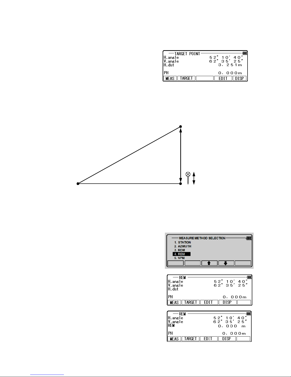
3.1 RDM (Remote Distance Measu ement)
With RDM, the Horizontal, Vertical and Slope distance and % of Slope between the Reference
point and the Target point are measured. Any Target point can be changed to the new
Reference point.
Press the [ENT][RDM] of the
inertecExpress screen to view
the “REF. point”
15
Target 1
Target 2
Ref. P
Station

3.1.1 PH INPUT
Press [F4] [EDIT] to input the PH,
Reference Point Height.
3.1.2 Refe ence Point-Ta get
Distance
Aim at the Reference point and press
[F1] [MEAS] to measure the Reference point.
It turns to TARGET POINT screen automatically.
Aim at the Target 1 and press [F1] [MEAS] to
measure a distance. The distance between
Reference point and Target point 1 is displayed.
V.dst. and % grade are displayed by minus mark
when the Target point height is at a lower position.
Press the [F3] [DATA] to view the TARGET
POINT screen.
3.1.3 Ta get-Ta get Distance
Aim at the Target 2 and press [F1] [MEAS] to
measure a distance.
The distance between Reference point and Target
point 2 is displayed.
Press [F5] [DISP] to display the distance between
Target1 - Target 2.
3.1.4 New Refe ence Point Selection
Press [ENT] to view the REF. POINT SE ECTION
screen.
New Ref. point can be selected.
16
Press the [F5] [ENT] to view the TARGET POINT
screen. Reference point is changed.
Input the new PH and repeat the same procedure as
the above.
3.2 REM
3.2.1 Gene al Pictu es of Measu ement
With REM measurement, a prism (Reference point) is set approximately directly below the
place to be measured, and by measuring the prism, the height to the target object can be
measured. This makes it easy to determine the heights of electric power lines, bridge
suspension cables, and other large items used in construction.
From the inertecExpress screen, Select [F2] [REM]
and press [ENT] to view MEASURE screen.
Please press [ENT] after measuring distance.
17
General Picture
Horizontal distance
Height
Prism Height
Prism
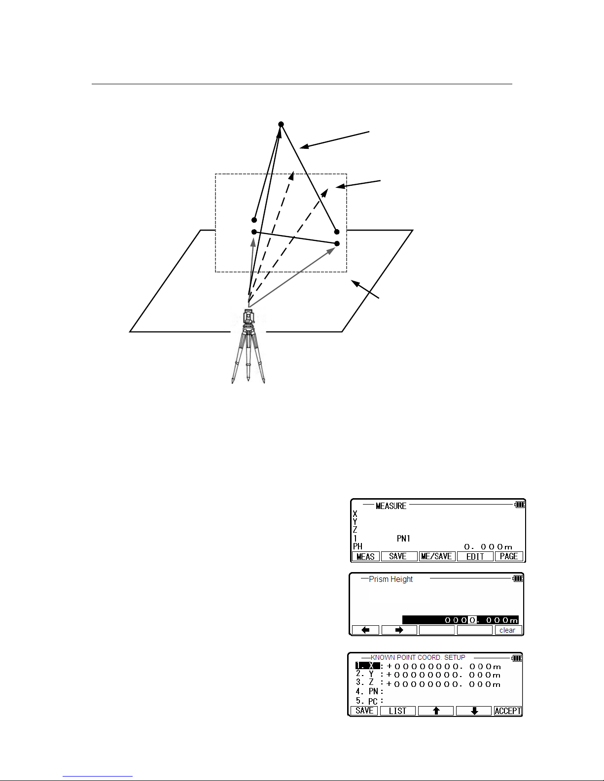
3.3. VPM
The Virtual plane includes the Vertical plane.
With VPM, the Coordinates on the vertical plane and virtual plane can be obtained by entering
the “Station Coordinates and Azimuth” and by measuring P1, P2 and P3.
Two points make a vertical plane and three points make a virtual plane.
You can measure the Point Coordinates of this virtual plane by aiming at your desired points.
Press [ENT] of the inertecExpress screen to view the
“Measure” screen .
Press[F4] [Edit] to input the Prism Height
of the reference point.
Press [ENT] to enter“KNOWN POINT
COORD. SETUP”screen.
18
P1
P2
P3
Azimuth
Station
Coordinates
Vertical plane created
by 2 points
Coordinates of your aimed
point on the vertical plane
Virtual plane created by 3 points

[ IST] Key
All stored points can be displayed as follows by
pressing [F2] [ IST].
Press the [F2] [ IST] to view POINT SE ECTION
FROM THE IST screen.
You can enter Coordinates data by applying the ist
data.
Press [ENT] to open the input window of PN, X, Y,
Z and IH value.
Input each Character or value and press [F5]
[ACCEPT] to view the STATION POINT
H. ANG E SETUP screen.
Input the H. angle by pressing [F2] [INPUT], [F3] [0SET] and [F4] [HO D] or Backsight
Coordinates by pressing [F5] [BSP].
Press [ENT] to open the input window when using [F5] [BSP].
Pressing [F2] [INPUT] Input any horizontal angle.
Pressing [F5] [BSP] The information for Back Sight
Point is obtained. Press [ENT] to finalize the input.
Aim at the reference point, then press [ENT] to
enter Multiple Orientation. For more details, refer to
“11.1.4 Multiple Orientation”. Following Multiple
Orientation, it takes you to MEASURE screen.
Aim at point 1 and press [F1] [ MEAS].
Measured Coordinates are displayed.
19

Press [ENT] to view the next MEASURE screen.
In the same manner, aim at point 2 and press [F1]
[ MEAS].
Measured Coordinates are displayed.
Press [ENT] to view the COORD.
ON THE VIRTUA P ANE screen.
Aim at your desired point and press [ENT].
The Coordinates which you aim at are displayed.
Press [MEAS] to view the next MEASURE screen.
Aim at point 3 and press [F1] [MEAS]. Measured
Coordinates are displayed.
Press [ENT] to view the COORD. ON THE
VIRTUA P ANE screen.
Aim at your desired point and press [ENT].
The Coordinates, which you aim at, are displayed.
Pressing [F4] [EDIT] can edit the Point Name and Prism Height.
Pressing [F5] [DISP] can switch displayed value
from Rectangular data to Polar data.
Press [F2] [SAVE] to save the measured data.
20
This manual suits for next models
2
Table of contents
Other Linertec Measuring Instrument manuals


