Link LSR 90 Technical specifications

APR 09, 2019
78593001
Link Mfg. Ltd.
223 15th St. N.E.
Sioux Center, IA USA
51250-2120
(712) 722-4868
Fax (712) 722-4779
QUESTIONS?
CALL CUSTOMER
SERVICE
1-800-248-3057
www.linkmfg.com
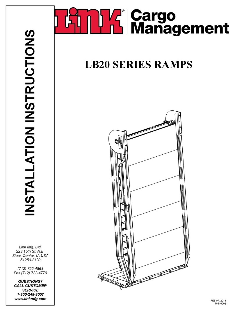
The LSR 90 fits Mercedes Benz Sprinters, Ford Transits mid and high
roof, Nissan NV high roof, and Ram Promasters.
UNIT WEIGHT: 300-350 LB.
MAINTENANCE
INSTRUCTIONS
LSR90 SERIES RAMPS

1. INTRODUCTION
Thank you for choosing a Link Cargo Management
Products LSR 90 Ramp. We want to help you to get the
best results from the ramp and to operate it safely. This
manual contains information to introduce you to the
Link LSR90 Ramp and to assist you with its operation.
The manual is intended solely for use with this product.
All information in this manual is based on the latest
information available at the time of printing. Link
Manufacturing reserves the right to change its products
or manuals at any time without notice. Contact Link
CMP at (800) 248-3057 for information on recent
changes to products.
Damaged components should be returned to Link with a
pre-arranged Returned Goods Authorization (RGA)
number through the Customer Service Department. The
damaged component may then be replaced if in
compliance with warranty conditions.
2. SAFETY SYMBOLS, TORQUE
SYMBOL, and NOTES
This is the safety alert symbol.
It is used to alert you to potential
personal injury hazards. Obey
all safety messages that follow
this symbol to avoid possible
injury or death.
WARNING
WARNING indicates a
potentially hazardous situation
which, if not avoided, could
result in death or serious injury.
CAUTION
CAUTION indicates a
potentially hazardous situation
which, if not avoided, could
result in minor or moderate
injury.
The torque symbol alerts you to
tighten fasteners to a specified
torque value.
3. SAFE WORKING PRACTICES:
3.1
3.2
4. OPERATION GUIDELINES
4.1 In order for this ramp to operate properly, it must
operate in the parameters specified by Link.
4.2 No alterations of any Link ramp component is
permitted without proper authorization from
qualified Link personnel.
IMPORTANT: IT IS IMPORTANT THAT THE EN-
TIRE OPERATION INSTRUCTIONS BE READ
THOROUGHLY BEFORE USING THIS SYSTEM.
• The operation of the LSR90 Ramp involves moving
parts.
• During the course of travel pinch points may exist be-
tween components.
• Keep hands and fingers clear of moving components
during operation.
CAUTION
• Practice safe lifting procedures.
• The ramp weldments are heavy, and can cause injury
if lifted improperly or dropped. Consider size, shape,
and weight of objects being moved.
• Obtain help or the assistance of a crane when lifting
heavy assemblies. Make certain the path of travel is
clear.
CAUTION

5. OPERATION
5.1 Ramp Operation
1. With the vehicle in park and the parking brake se-
cured, open the rear door of the vehicle.
2. Release the rotatory latch (midway up the side of
ramp on the passenger side near the handle).
3. Fold ramp out of the rear of the vehicle.
5.2 Ramp Swivel Out Operation
1. With the vehicle in park and the parking brake
secured, open the rear door of the vehicle.
2. To swivel the ramp out of vehicle.
3. Release the latch on the passenger side of vehicle
by pulling the rear yellow handle upward.
4. Swing the ramp out till the ramp swivel lock en-
gages.
5. To release ramp pull the swivel lock and swing
ramp until latched into latch.
5.3 Ramp Swivel In Operation
1. With the vehicle in park and the parking brake
secured, open the rear door of the vehicle.
2. To swivel the ramp into vehicle.
3. Release the latch on the passenger side of vehicle
by pulling the forward yellow handle upward.
4. Swing the ramp in till the ramp swivel lock engag-
es and the ramp is resting on the inside deck
catch .
5. To release ramp pull the swivel lock and swing
ramp outwards until latched into latch.
6. MAINTENANCE
The LSR90 is designed to last for many years without any
major maintenance. Periodically, check
the following items:
Each Time the Ramp is Used:
• Listen for unusual noises and watch to ensure prop-
er movement of the ramp. If there is a problem,
correct it before continuing to use the system.
Annually:
• Check tightness of all fasteners. (Refer to Torque
Table below)
• Visually inspect for cracks or damage at all pivots
on the framework and replace if necessary.
• Make certain the vehicle is in park and the parking
brake is engaged before loading / unloading the vehi-
cle.
• Vehicle movement during loading / unloading could
cause operator injury or death.
WARNING
• Loading beyond the capacity may result in equip-
ment damage or failure that may result in severe inju-
ry or death.
WARNING
• Do not use ramp if not locked into latch. Damage or
failure of ramp may occur that may result in severe
injury or death.
WARNING
• Do not use ramp if not locked into latch. Damage or
failure of ramp may occur that may result in severe
injury or death.
WARNING
• Park the vehicle in a level, flat area,
and apply the parking brake before
performing any maintenance.
CAUTION
TORQUE TABLE
FASTENER TORQUE
3/8-UNC NUTS 30-40 FT-LBS
7/16-UNC NUTS 50-60 FT -LBS
1/2-UNC NUTS 80-100 FT-LBS

With the ramp in the folded upright position. Using a
9/16” wrench turning counter clockwise loosen the two
7/16” bolts two full turns.
Using the same 9/16” wrench turn the top bolt clockwise to raise
the ramp and counter clockwise to lower the ramp.
Turn the bolt in 1/4” increments in order to achieve the correct
height that the ramp swings into the catch latch.
RAMP ADJUSTMENT PROCEDURE

Turning clockwise tighten the two 7/16” bolts
RAMP ADJUSTMENT PROCEDURE CONT.

** CONTACT CUSTOMER SERVICE FOR CORRECT PART NUMBER FOR YOUR RAMP
ITEM PART # DESCRIPTION QTY
114171606 1/2 X 3/4 UNC SOC FLAT CSK HD CAP SCREW 8
214261208 3/8 X 1 UNC SOCKET HEAD CAP SCREW (GRADE 8) 2
314490003 PIN-COTTER, .1875 X 2.00 1
414780800 1/4 UNC HEX NYLOCK NUT (GR B) 1
515000962 BEARING-ROLLER, TAPPERED 2
615060568 LOCKNUT-SLOTTED, 1"-14 1
715070407 BUMPER-RECESSED, 1.50 O.D. X .63 H 1
878590019 BRACKET-MOUNT, T-BAR 1
978590095 PLATE-UPPER, HOLD DOWN 1
10 78590100 PLATE-UPPER, HOLD DOWN 1
11 ** PLATE-MOUNT 1
12 78591002 WELDMENT-SWIVEL 1
13 78591012 ASSEMBLY-LATCH 1
14 78591013 ASSEMBLY-PIN, MOUNT 1
15 78591016 ASSEMBLY-SWIVEL LOCK 1
16 144C0808 1/4 X 1 UNC TRUSS HD PH MACH SCR, SS 1

ITEM PART # DESCRIPTION QTY ITEM PART # DESCRIPTION QTY
114011006 5/16 X 3/4 UNC HEX CAP SCR (GR 5) 317 78590042 MOUNT- OUTSIDE,LEFT 1
214490006 PIN-COTTER, .072 X 1.09 118 78590047 MOUNT-SPACER,LEFT 1
314780800 1/4 UNC HEX NYLOCK NUT (GR B) 419 78590048 SUPPORT- MOUNT, RIGHT 1
414781200 3/8 UNC HEX NYLOCK NUT (GR B) 10 20 78590049 MOUNT-SPACER, RIGHT 1
514851000 5/16 LOCK WASHER 321 78590050 MOUNT-INSIDE, RIGHT 1
614870800 1/4 TYPE A PLAIN WASHER 422 78590053 MOUNT- OUTSIDE,LEFT 1
714871000 5/16 TYPE A PLAIN WASHER 223 78590054 MOUNT-INSIDE, LEFT 1
814871200 3/8 TYPE A PLAIN WASHER 10 24 78591010 GUSSET-SIDE, SWIVEL 1
915000961 BEARING-NYLON, 1.00 ID X 1.50 125 ** WELDMENT-DECK,UPPER 1
10 15000965 BEARING-DOUBLE SHIELDED, 1 1/4" SHAFT 126 ** WELDMENT-HINGE PLATE 1
11 15000966 CAP-PUSH NUT, UNTHREADED 227 142C1608 1/2 X 1 UNC SOCKET BUTTON HD CAP SCR 2
12 60002107 SPRING-COMPRESSION 128 142D1414 HEXAGON SOCKET BUTTON HEAD CAP SCREW, SS, 3/8 X 1.75 UNC 6
13 78590016 PIN-HINGE, RIGHT 129 142D1416 HEXAGON SOCKET BUTTON HEAD CAP SCREW, SS, 3/8 X 2.00 UNC 4
14 ** ROD-HINGE 130 144C0814 1/4 X 1 3/4 UNC TRUSS HD PH MACH SCR, SS 4
15 78590024 CAP-HINGE PIN 131 144C-0804 1/4 X 1/2 UNC TRUSS HD PH MACH SCR, SS 8
16 78590030 MOUNT-BEARING,INSIDE 1
** CONTACT CUSTOMER SERVICE FOR CORRECT PART NUMBER FOR YOUR RAMP

** CONTACT CUSTOMER SERVICE FOR CORRECT PART NUMBER FOR YOUR RAMP
ITEM PART # DESCRIPTION QTY
114010808 1/4 X 1 UNC HEX CAP SCR (GR 5) 4
214011012 5/16 X 1 1/2 UNC HEX CAP SCR (GR 5) 2
314011216 3/8 X 2 UNC HEX CAP SCR (GR 5) 8
414011616 1/2 X 2 UNC HEX CAP SCR (GR 5) 1
514300013 SHSCS-.312X2.000 2
614780800 1/4 UNC HEX NYLOCK NUT (GR B) 6
714781000 5/16 UNC HEX NYLOCK NUT (GR B) 2
814781600 1/2 UNC HEX NYLOCK NUT (GR B) 1
914851200 3/8 LOCK WASHER 8
10 14870800 1/4 TYPE A PLAIN WASHER 4
11 14871000 5/16 TYPE A PLAIN WASHER 2
12 15000968 LOCK-ROTARY, RIGHT HAND 1
13 15001311 DECAL-PINCH POINT 2
14 15040317 CLEVIS-DOUBLE 2
15 15040337 SPRING-GAS (250LB) 2
16 15080112 WASHER-PLASTIC, .53 ID X 1.25 OD X.063 THK 2
17 78420016 CAP - BEARING 4
18 78425103 PLATE-SPRING, ADJUSTER 1
19 78425106 WELDMENT-SPRING MOUNT, LEFT 1
20 78425107 WELDMENT-SPRING MOUNT, RIGHT 1
21 78425108 PLATE-SPRING, ADJUSTER 1
22 78590065 BEARING - HALF, 1" 8
23 78591009 ASSEMBLY-TIE ROD 1
24 ** ARM - TORQUE 47" 1
25 141C1020 5/16 X 2 1/2 UNC HEX FULLY THREADED CAP SCR (GR 5) 2

** CONTACT CUSTOMER SERVICE FOR CORRECT PART NUMBER FOR YOUR RAMP
ITEM PART # DESCRIPTION QTY
114090806 1/4 X 3/4 UNC HEX CAP SCR, SS 6
214780800 1/4 UNC HEX NYLOCK NUT (GR B) 2
314781400 7/16 UNC HEX NYLOCK NUT (GR B) 1
414840810 1/4 UNC HEX CTR LOCK NUT, SS 6
515000969 STRIKER-.55 1
615070478 ROLLER-IDLER,ASSEMBLY 2
778425111 MOUNT, SUPPORT WHEEL 2
878500004 HANDLE-LB10 1
978590105 PLATE-MOUNT, STRIKER 1
10 78590108 BUMPER-RUBBER, SWIVEL RAMP 2
11 ** WELDMENT-DECK, LOWER 47" X 99" 1
12 144C0810 1/4 X 1 1/4 UNC TRUSS HD PH MACH SCR, SS 2

ITEM PART # DESCRIPTION QTY ITEM PART # DESCRIPTION QTY
114010810 1/4 X 1 1/4 UNC HEX CAP SCR (GR 5) 218 78590056 PLATE-COVER, BEARING 1
214010814 1/4 X 1 3/4 UNC HEX CAP SCR (GR 5) 319 78590061 CHANNEL-SUPPORT 1
314011412 7/16 X 1 1/2 UNC HEX CAP SCR (GR 5) 220 78590062 CHANNEL-SUPPORT 2
414011614 1/2 X 1 3/4 UNC HEX CAP SCR (GR 5) 121 78590064 CHANNEL-SUPPORT 1
514011620 1/2 X 2 1/2 UNC HEX CAP SCR (GR 5) 222 78590104 SUPPORT- UNDER FLOOR, INSIDE CATCH 1
614050812 HEX CAP SCREW, M8 X 1.25 X 60, CLASS 8.8 123 78590106 SUPPORT- UNDER FLOOR, INSIDE CATCH 1
714780800 1/4 UNC HEX NYLOCK NUT (GR B) 524 78591014 CATCH-INSIDE, SWIVEL RAMP 1
814781600 1/2 UNC HEX NYLOCK NUT (GR B) 425 141C1416 7/16 X 2 UNC HEX FULLY THREADED CAP SCR (GR 5) 1
914821601 1/2 UNC FLANGE NUT (GR G) 626 142C1622 1/2 X 2 3/4 UNC SOCKET BUTTON HD CAP SCR 6
10 14851000 5/16 LOCK WASHER 127 144C0804 1/4 X 1/2 UNC TRUSS HD PH MACH SCR, SS 7
11 14870800 1/4 TYPE A PLAIN WASHER 728 144C0808 1/4 X 1 UNC TRUSS HD PH MACH SCR, SS 1
12 14871000 5/16 TYPE A PLAIN WASHER 129 144C0810 1/4 X 1 1/4 UNC TRUSS HD PH MACH SCR, SS 8
13 14871400 7/16 TYPE A PLAIN WASHER 330 1500-0071 BUMPER-JOUNCE, 1.25 1
14 14871600 1/2 TYPE A PLAIN WASHER 231 1500-1311 DECAL-PINCH POINT 4
15 15000965 BEARING-DOUBLE SHIELDED, 1 1/4" SHAFT 132 1508-0112 WASHER-PLASTIC, .53 ID X 1.25 OD X.063 THK 9
16 78590007 MOUNT-BEARING, OUTSIDE 133 7000-0031 WASHER-FLOOR SUPPORT 6
17 78590051 BLOCK-REST,INSIDE 134 7850-3005 GUARD-PINCH POINT 2

Link Mfg. Ltd.
223 15th St. N.E.
Sioux Center, IA USA
51250-2120
Table of contents
Other Link Lifting System manuals