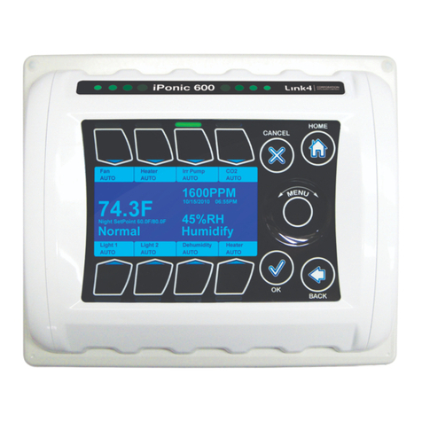
Link4 iPonic 624 User manual

iPonic®624
DUAL-ROOM HYDROPONIC ENVIRONMENTAL CONTROLLER
INSTALLATION AND USER’S GUIDE
September 2019 v2.0 Edition
Copyright © 2019 ®Corporation

iPonic 624® Manual PN 995-1124-00
2| Page
TABLE OF CONTENTS
Gold Package Customers..................................................................................4
Contact Us ............................................................................................................. 4
Terms and Conditions..........................................................................................4
Limited Warranty.............................................................................................4
Return, Exchange or Refund............................................................................5
Install the iPonic® 624 Controller.......................................................................6
Choosing Location............................................................................................. 6
Mounting the iPonic®624 Controller.............................................................. 6
Connect the Indoor Sensor Modules ...............................................................7
Connecting to the Internet ...................................................................................9
Firmware Update................................................................................................ 12
Internal Layout...................................................................................................16
Before You Begin –Some Basics ....................................................................... 17
Setpoints........................................................................................................... 17
Temperature Control...................................................................................... 17
Deadbands........................................................................................................18
Ramping........................................................................................................... 18
Programming Instructions ............................................................................. 19
Control Panel................................................................................................... 20
Soft Button Shortcuts ......................................................................................... 21
1.0 Main Menu —SETPOINTS........................................................................24
1.1 SETPOINTS Menu ─ Temperature Setpoint ....................................... 25
1.2 SETPOINTS Menu ─ Humidity Setpoint............................................. 27
1.3 SETPOINTS Menu ─ CO2 Setpoint..................................................... 28
1.4 SETPOINTS Menu ─ Light Setting...................................................... 31
1.5 SETPOINTS Menu ─ Setpoint Times................................................... 32
2.0 Main Menu —REPORTS............................................................................33
2.1 Reports –Sensor Report...........................................................................33
2.2 Reports –Graphs....................................................................................... 34
3.0 Main Menu —SYSTEM SETUP................................................................ 35
3.1 SYSTEM SETUP Menu ─ Equipment Setup .......................................... 37
3.1.1 Quick Setup......................................................................................... 37
3.1.2 Advanced............................................................................................. 38
3.1.2.1 Equipment Settings —Timed Override ...................................... 39
3.1.2.2 Equipment Settings —Initial Settings........................................ 41
3.1.2.2.1 Equipment Settings —Set Name........................................... 41

iPonic 624® Manual PN 995-1124-00
3| Page
3.1.2.2.2 Equipment Settings —Set Type.............................................42
3.1.2.2.3 Equipment Setttings —Assign Stage.....................................45
3.2 SYSTEM SETUP Menu ─ Sensor Setup .................................................46
3.3 SYSTEM SETUP Menu ─ Alarms Setup.................................................49
3.4 SYSTEM SETUP Menu ─ Time/Date Setup ...........................................50
3.5 SYSTEM SETUP Menu ─ Advanced.......................................................51
3.5.1.1 Advanced Room 1 or Room 2 —Humidity Settings.................52
3.5.1 –Advanced Room 1 or Room 2 ...........................................................52
3.5.1.2 Advanced Room 1 or Room 2 —Temperature Settings...........53
3.5.1.3 Advanced Room 1 or Room 2 —CO2 Settings .........................53
3.5.1.4 Advanced Room 1 or Room 2 —Light Settings........................54
3.5.1.5 Advanced Room 1 or Room 2 —Air Exchange Settings..........55
3.5.1.6 Advanced Room 1 or Room 2 —Advanced Stage Settings......55
3.5.1.7 Advanced Room 1 or Room 2 —Adv. Setpoint Settings..........56
3.5.2 Advanced Shared .................................................................................57
3.5.2.1 Display Setting..............................................................................58
3.5.2.2 Controller Version........................................................................59
3.5.2.3 Clear Data.....................................................................................59
3.5.2.4 Boot Load......................................................................................59
3.5.2.5 Password .......................................................................................60
3.5.2.6 Start Wizard .................................................................................60
3.5.2.7 Diagnostics ....................................................................................60
3.6 SYSTEM SETUP Menu ─ Save/Restore..................................................61
3.7 SYSTEM SETUP Menu ─ Communication Setup..................................63
3.8 SYSTEM SETUP Menu ─ Measurement Units.......................................64
4.0 Main Menu —SAVE/RESTORE CONFIGURATION............................64
5.0 Main Menu —STAGES...............................................................................66
Appendix A —CO2Fuzzy Logic.......................................................................68
iPonic 624 ® User Manual Index...........................................................................1

iPonic 624® Manual PN 995-1124-00
4| Page
Customer Service
At Link4®, we are committed to providing professional, efficient and high-quality
solutions and support for your grow room business. For Technical Support service
during Monday to Friday (not including holidays), from 6:00 a.m. to 6:00 p.m.
hours, weekends and holidays, please leave a message and your call or email will
be responded to by the next business day.
If a highly critical need arises during non-business hours, please call our main
office line at 866-755-5465 and leave a message. These calls are screened, and if
they meet the criteria for an emergency, a call will be returned before the next
business day.
Gold Package Customers —please refer to the private phone number on your
warranty letter to access emergency support after hours, on weekends and
holidays.
Contact Us
Address:
Website:
Link4 Corporation
175 East Freedom Avenue
Anaheim, CA 92801
http://www.link4controls.com
Telephone:
Email:
(714) 524-0004 Main
Telephone
(866) 755-5465 Toll Free
(714) 975-9474 Customer
Service
(714) 854-7244 Facsimile
Sales:
sales@link4controls.com
Customer Service:
support@link4controls.com
Terms and Conditions
Limited Warranty
Link4 warrants that the goods sold will be free from defects in material and
workmanship for a period of 12 months after the date of purchase. This warranty
will be limited to the repair and replacement of parts and the necessary labor and
services required to repair the goods. IT IS EXPRESSLY AGREED THAT THIS
WARRANTY WILL BE IN LIEU OF ALL WARRANTIES OF FITNESS AND
IN LIEU OF THE WARRANTY OF MERCHANTABILITY.
Moreover, any description of the goods contained in this Installation and User’s
Guide is for the sole purpose of identifying them, is not part of the basis of the
bargain, and does not constitute a warranty that the goods will conform to that
description. The use of any sample or model in connection with this Installation
and User’s Guide is for illustrative purposes only, is not part of the basis of the

iPonic 624® Manual PN 995-1124-00
5| Page
bargain, and is not to be construed as a warranty that the goods will conform to
the sample or model. No affirmation of fact or promise made by Link4, whether
or not in this Installation and User’s Guide, will constitute a warranty that the
goods will conform to the affirmation or promise.
Link4 shall not be responsible for replacement(s) or repair(s), which become
defective from user negligence, modification, abuse, any types of improper usage,
acts of God and/or force majeure. Nonconformance to any of the specifications in
the product manual will void the warranty. Furthermore, Link4’s liability to the
goods sold, whether on warranty, contract, or negligence, will be released upon
the expiration of the warranty period when all such liability shall terminate.
Link4 shall not be responsible for any loss or claims due to consequential
damages afford by the Buyer. Link4 also reserves the right to make any necessary
changes to features and specifications to condition or warranty.
Return, Exchange or Refund
Please refer to Link4’s Return and Exchange Policy at
http://link4controls.com/support.
Inspect Your Package
Upon arrival, check the contents with the packing list to ensure that you have all
the items, all associated hardware and the necessary tools to begin installation.
Make sure nothing is damaged or missing. If there is any visible damage or
missing parts, please contact your point-of-purchase customer service department
immediately. The package should come complete with the items listed below:
Item
Quantity
iPonic 624 controller
1
Digital Integrated Sensor Modules
(DISM) with 16 ft. cable*
2
Preinstalled internet communication
module
1
Quick start guide
1
User manual
1

iPonic 624® Manual PN 995-1124-00
6| Page
Grow Room 1
Grow Room 2
*DISM 50ft. extension cable (PN 995-0020-00) is available for purchase from Link4:
Install the iPonic® 624 Controller
Choosing Location
Find a location outside the grow room to mount your iPonic 624 controller. The
following factors should be taken into consideration:
- secure and easily accessible;
- have a sturdy surface to hold the weight of the controller and the
additional weight of the equipment power cords;
- away from direct sunlight and grow lights;
- dry area with no condensation, moisture, humidity, rain and extreme
temperatures; and
- have at least ten inches of workspace below the controller.
Mounting the iPonic®624 Controller
There are four (4) mounting holes on the outside of the iPonic 624 enclosure to
help you attach it to a suitable surface. Make sure you use appropriate tools.
The iPonic 624 controller comes with a 115 VAC power cord. Make sure there is
an outlet within approximately six (6) feet of the controller. It is highly
recommended that you use an outlet that is not shared with another high-voltage
equipment. You must disconnect all equipment from the iPonic 624 controller
before its initial start-up.

iPonic 624® Manual PN 995-1124-00
7| Page
SAFETY WARNING
The iPonic 624 controller supports a maximum of 15 amps at 115 VAC. It is
recommended that the total current for both rooms be no more than 12 amps. To
avoid electric shock, always keep the hinged door closed and locked when the
controller is powered on.
If the total current for the equipment connected to the iPonic exceeds 12 amps,
then external relays/contactors are required. See Appendix B for a suggested
wiring diagram.
Connect the Indoor Sensor Modules
The iPonic 624 controller comes with two Digital Integrated Sensor Modules
(DISM) –one for each room.
These sensors measure humidity, temperature,
CO2 and light. It is recommended that you hang
each sensor in a central location within the grow
room facility. Ideally, you want to hang the module
near the crop level and towards the center point of
the controlled environment to produce accurate
readings. You may want to keep the module away
from irrigation emitters, unit heaters, and/or any
other type of equipment that may affect the
accuracy of the sensors.
Securely connect the sensor modules to the plug-in connectors at the bottom of the
iPonic 624 controller. For accurate Light Sensor readings, make sure the Light
Sensor, which is at the top of the DISM module near the cable, is facing upward
and toward the lighting sources in the room. Because of the sensitivity of the
sensors, you may want to experiment with different locations and positions to
determine the best area for getting the most accurate light sensor readings.
Each sensor module comes with a 16-foot cable. You may lengthen and extend the
cables as needed but make sure to use Link4 Extension Cables, Junction Boxes and
wires approved by Link4. Cutting and splicing can result in unstable sensor readings
and failures.
DISM Top View

iPonic 624® Manual PN 995-1124-00
8| Page
CAUTION: Keep the cables away from high-voltage wiring, power inverters,
motor controllers, mercury arc and/or sodium lamp circuits.
Wiring the iPonic® 624
At the base of the iPonic 624 controller are the two sensor plugs and the Ethernet
cable grommet for internet access. Adding extra holes elsewhere on the enclosure
can result in condensation or moisture inside the unit and cause irreparable
damages to your iPonic 624 controller. Failure to install the iPonic 624
controller to Link4’s specifications will void the warranty.

iPonic 624® Manual PN 995-1124-00
9| Page
The iPonic 624 controller has eight 115 VAC electrical outlets. The default setting
is four outputs for each of two rooms. With the program you can modify the
number of outputs for each room, or even have all eight outputs in one room.
Connecting to the Internet
The iPonic 624 controller comes with a preinstalled Communication Module,
which can be used to access the Internet via a standard CAT 5 cable linked to your
router.
Note: The Ethernet port for the Internet is inside the iPonic 624 controller. Before
proceeding, make sure the Ethernet cable is functioning properly.
To connect your iPonic 624 controller to the Internet:
- Power down the controller
- Open up the hinged door
- Route cable through opening at the base

iPonic 624® Manual PN 995-1124-00
10| Page
- Locate Ethernet port at upper left corner
- Plug in the cable to Ethernet port
- Plug in the other end to your router
- Close and lock the controller door
- Power up the controller
Once you are connected to the Internet, the iPonic 624 controller will
automatically link up to the iPonic Cloud server at https://iponic.link4cloud.com
and the Server Setup screen connection status will display “Check Account.”
Once you add your iPonic 624
controller onto the iPonic
Cloud**, the connection
status will display OK.
**Use the instructions below
to access the iPonic 624
controller’s Serial Number and
Registration Passcode to add
your controller onto the iPonic
Cloud.
-From the Main Menu, Press Soft Button No. 3 or use the Navigation
Menu to highlight System Setup
-Press Soft Button No. 7 or use Navigation Menu to highlight
Communication Setup
-Press Soft Button No. 2 or use Navigation Menu to highlight Server
Setup
-View your Serial Number and Registration Passcode
Go to the browser on your computer or mobile phone and visit the iPonic Cloud
at https://iponic.link4cloud.com. If you have not done so already, create an
account.
Remote Access

iPonic 624® Manual PN 995-1124-00
11| Page
To set up your iPonic 624
controller for remote access
through your computer or
smartphone, follow these 3
steps:
Step 1 –Login to your
account and click on “My
iPonic Cloud”
Step 2 –Click on “Add a
Controller to Your
Account”
Step 3 –Enter the Serial
Number, Registration
Passcode and select “ADD
CONTROLLER”

iPonic 624® Manual PN 995-1124-00
12| Page
Firmware Update
To update the firmware on your iPonic 624 controller, please follow the
instructions below:
-From the Home screen of your Link4’s iPonic Cloud account, click on
the Support tab and select Firmware Download
-On Firmware Download screen click on Latest iPonic Firmware
-Create a New Folder on your desktop and name it PRG
-Retrieve iPonic Firmware UPDATE and move it to your PRG folder
-Move the PRG folder to an empty USB drive
-Safely remove your USB drive from your computer
-Insert your USB drive into your iPonic 624 controller
-Turn the Navigation Menu to launch the Main Menu
-Press Soft Button No. 3 or use the Navigation Menu to select System
Setup option
-Press OK to confirm selection and proceed to the System Setup Menu
-Press Soft Button No. 5 or use the Navigation Menu to select
Advanced option
-Press OK to confirm selection and proceed to Room Select
-Use the Soft Buttons or Navigation Menu to select Shared
-In the Advanced Setup menu, press Soft Button No. 4 for Bootload
-You will be asked to begin Bootload
Congratulations! You now can
remotely access your iPonic 624
controller through your
computer or smartphone.

iPonic 624® Manual PN 995-1124-00
13| Page
-Use the Navigation Menu to answer Yes
-Press OK to confirm your settings
-You will be asked if you want to Reprogram
-Use Navigation Menu to answer Yes
-Press OK to confirm your settings
-You will be asked if you want to Configure from the USB drive
-Use Navigation Menu to answer Yes
-Press OK to confirm your settings
-A status message will appear, and the iPonic 624 controller will restart
WARNING: The iPonic 624 controller is equipped with a USB port (use the slot
on top). For your safety, please shut down and unplug your iPonic 624 controller
before inserting the USB drive. You can use the USB drive to import schedules,
install programs and upgrade your firmware. Please refer to this User Manual for
more information.
Main Status Screens
The iPonic 624 controller has three Main status screens. The default status screen
is divided between two rooms. The top section displays the current status for
Room 1, and the bottom section displays the current status for Room 2.
Split screen view featuring two rooms
If you press the Home button, the whole screen will contain detailed information
for Room 1. Pressing the Home button, a second time will give you the detailed
information for Room 2. The two screens are shown on the next page.

iPonic 624® Manual PN 995-1124-00
14| Page
The names of the equipment being controlled, and their current control status are
displayed at the top of Room 1 screen and the bottom of the Room 2 screen. All of
the numerical values shown below are samples only and will differ for each user.
Room 1 Main Screen with Day Setpoints
Room 2 Main Screen with Night Setpoints
Temperature –Each room has its own temperature sensor with its value
displayed to one decimal point. (Fahrenheit or Celsius are selectable options)
CO2–Carbon dioxide levels are measured in parts per million (ppm) in each
room.
Humidity –Relative humidity is displayed for each room as a percentage.
Setpoint –If the controller is in Daytime mode, it will display Day cooling and
heating setpoints. Similarly, if the controller is in Night mode, it will display both
the night heat and night cool setpoints.
Current Temperature and or Humidity Stage –The real-time temperature
stage will be displayed below the temperature display. It will be either Normal,
Heat 1 or 2, or Cool 1 thru 6, depending on number of stages you assign. If the
controller is in humidify or dehumidify state, this real-time condition will be
displayed below the relative humidity reading.
Soft Buttons –The buttons at the top and bottom of the screen correspond to the
equipment being controlled. Below the name of the equipment is the current status

iPonic 624® Manual PN 995-1124-00
15| Page
of the output. The normal condition is Auto mode. Pressing a button will highlight
the override options for that piece of equipment, the most basic being Manual
Override of the output. Each output can be forced ON or OFF.
An alternative to forcing the equipment ON or OFF is to use the manual override
switches that are inside the controller. These switches are shown in the figure of
the internal layout on pages 17 and 20.

iPonic 624® Manual PN 995-1124-00
16| Page
Very Important:
Note: The manual switches inside the controller take precedence over the soft
button override. Therefore, when the system is running normally, the Manual
Override switches inside the controller must be in the AUTO position. If not,
they will override all programmed settings
Internal Layout
The diagram below shows the iPonic 624 controller’s internal layout and
components. There are eight Manual Override Switches, a Reset Button that
clears all configurations, a preinstalled Communication Module with an
Ethernet port, and a USB slot (use the slot on top). Make sure the power is turned
off before opening your iPonic 624 controller to avoid electric shock or
irreparable damages.

iPonic 624® Manual PN 995-1124-00
17| Page
Before You Begin –Some Basics
Setpoints
The iPonic 624 controller lets you program up to three different temperature and
humidity Setpoint pairs over a twenty-four-hour period. For both temperature
and humidity control you can select a low setpoint and a high setpoint. Typically,
if the room temperature is above the high setpoint, the system will be in a cooling
stage. Similarly, if the room temperature is below the low setpoint, the system will
be in a heating stage. For each stage certain equipment’s can be programmed to
be on for the purpose of driving the temperature or humidity in the room to the
Normal stage, that is, the temperature or humidity between the high and low
setpoints.
If you want the setpoint pairs to change during the 24-hour period (which you can
do up to three times), then you have the option of ramping between the setpoint
pairs. This gives you the option of a smooth transition between the two setpoints
from one time period to the next.
Below is an example of a setpoint worksheet for temperature and relative
humidity. If you want separate day-night setpoints, then for setpoint 1 enter the
day start time and setpoint 2, the night start time. Then fill in the data for the two
setpoints.
Temperature Control
With the iPonic 624 controller, you can set a normal temperature range for your
cooling and heating equipment by programing a cooling temperature target (Cool
Setpoint) and a heating temperature target (Heat Setpoint), respectively. The
temperature-control equipment will not be activated when the grow room
temperature is within the normal range. Some circulation fans, which are also
known as horizontal air flow or HAF fans, may be activated to maintain air
movement within the grow room environment.
Anytime the temperature within the grow room deviates from the normal
temperature range, whether above the Cool Setpoint or below the Heat Setpoint,
the controller will activate the temperature-control equipment to enter either a
cooling stage or a heating stage to drive the grow room environment to the desired
normal temperature range. With the iPonic 624 controller, you can program up to
6 cooling stages and 2 heating stages.

iPonic 624® Manual PN 995-1124-00
18| Page
When the temperature in the grow room rises above the Cool Setpoint, the system
enters the first stage of cooling (referred to as Cool 1). If the temperature
continues to rise, the system will enter the second stage (Cool 2), then the third
stage (Cool 3) and so forth. The goal is to drive the temperature to the normal
temperature range.
The same occurs when the temperature drops below the Heat Setpoint. The only
difference is that there is a maximum of two heating stages.
Deadbands
If the room temperature rises above the Cool Setpoint, the cooling equipment will
be activated to bring the temperature back to the normal temperature range.
Without a deadband, this can cause the system to “short cycle” – that is, oscillate
rapidly between the cooling stage and the normal stage. To limit the oscillations, a
temperature band (deadband), often 1-2 degrees, is set below the temperature cool
setpoint. As the temperature rises in the room and exceeds the cool setpoint, the
first stage of cooling is engaged. When the room temperature drops below the cool
setpoint, it remains in its first stage of cooling until the temperature drops below
the cool setpoint –the deadband. Then it goes into the Normal stage. The
narrower the deadband, the more the equipment goes on and off, but the tighter
the temperature control.
The same process occurs with the Heat Setpoint. In this case, as the room
temperature falls below the heat setpoint, the heating equipment is engaged.
When the heat rises above the heat setpoint, it stays on until the temperature
exceeds the heat setpoint + the deadband.
The temperature staging, deadbands and ramping are illustrated in the figure
below.
Deadbands are also used with humidity control, CO2control and light control.
Ramping
Ramping lets you controlhow gradually or rapidly you want to change the temperature
and humidity targets between setpoint periods. If the night temperature targets are less
than the day targets, for example, you may want to gradually adjust the setpoints so as
not to shock theplants. Besides being good for the plants, it can also save on energy.
However, there are cases, depending on the crop, where sharp ramping, or a quick
increase or decrease of theplanttemperature is desirable. This issometimes referred to
as DIF.
By default, the Ramp time is set to 0 and in this case, there will be an immediate step
transition in the setpoints. If you enter a Ramp time, it will always occur at the
beginning of the Set Point time period. Example of temperature ramping is illustrated
below:

iPonic 624® Manual PN 995-1124-00
19| Page
In this Example:
Setpoint 1 is set to 8:00 a.m. with a 60 minutes Ramp, Temp is set as 68 to 72.5F
Setpoint 2 is set to 6:00 p.m. with a 30 minutes Ramp, Temp is set as 67 to
70.5F
Programming Instructions
Before programming the iPonic 624 controller, make sure the equipment has been
properly connected and tested with the Manual Override Switches. After all
equipment is tested, the switches must be placed back to the AUTO position.

iPonic 624® Manual PN 995-1124-00
20| Page
MENU
Use theNavigationMenuto
highlight a selection. Press OK to
confirm the selection. The center
of the Navigation Menu is NOT a
button. If an alphanumeric field is
highlighted, the Navigation
Menu can increase or decrease
the value of the entry or move
between the options on the screen.
HOME
The Home button always takes you
back to the Mainstatus screen. If
changes have been made, you will
be prompted to save the data.
CANCEL
Pressing CANCEL in the middle
of an entry will bring you back
to the previous level without
making any changes.
OK
Pressing OK will prompt the
system to accept the selected
MENU entry or save your data.
BACK
The BACK button will take you up
one level. You will be prompted to
save data if needed.
Control Panel
The iPonic 624 controller has a Navigation Menu and four (4) Soft Buttons (HOME,
CANCEL, OK, and BACK). Their functions are as follows:
Use the Navigation Menu to
highlight a selection. Press OK to
confirm the selection. The center of
the Navigation Menu is NOT a
button. If an alphanumeric field is
highlighted. The Navigation Menu
can increase or decrease the value of
the entry or move between the options
on the screen.
The Home button always takes you
back to the Main status screen. If
changes have been made, you will be
prompted to save the data.
Pressing CANCEL in the middle of
an entry will bring you back to the
previous level without making any
changes.
Pressing OK will prompt the system
to accept the selected MENU entry or
save your data.
The BACK button will take you up
one level. You will be prompted to
save data if needed.
Other manuals for iPonic 624
1
Table of contents
Other Link4 Controllers manuals
Popular Controllers manuals by other brands
Balluff
Balluff SmartVision BAE PD-VS-014-05 user manual
Cooper Tools
Cooper Tools Cleco mPro400GC Quick setup guide

dunkermotoren
dunkermotoren BGE 6e operating manual
DKM Motor
DKM Motor DSA Series instruction manual
Field Controls
Field Controls 4615900 instructions
Avid CNC
Avid CNC NEMA 23 Technical manual
