Link4 iPonic 614 Alert User manual

iPonic™ 614 Alert
990-0701-00
Single-Room Cloud based
monitoring and Alarm System
Controller
User Manual
840-0100-00
Revision 1
Copyright © 2019 Link4 Corporation

P/N: 840-0100-00 Revision 1 Page 2 of 15
Table of Contents
Introduction ...................................................................3
Customer Service ..........................................................4
Contact Us……. ......................................................................4
Terms and Conditions .................................................5
Installation......................................................................6
Inspect Your Package...........................................................6
Contents..................................................................................6
Mount Your iPonic™ 614............................................7
Connect To The Internet.............................................8
Remote Access................................................................9
Control Panel................................................................10
Sensor Setup.......................................................................11
Alarms Setup......................................................................13
Time/Date Setup...............................................................14
Communications Setup……………….………………….15

P/N: 840-0100-00 Revision 1 Page 3 of 15
Introduction
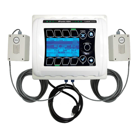
Thank you for purchasing the newest edition of Link4’s illustrious
lineup of innovative hydroponic controllers. The iPonic™ 614 Alert is
a cloud based monitoring and alarm system. With simple plug-and-
play functionality, any grower can see what is going on in their
facility –from any internet connected device.
The iPonic Alert is ideal for the cultivator that is satisfied with their
current controls, but wants the extra assurance of push notifications
sent to their smart phone in the event anything should go wrong.
The iPonic Alert comes with a Digital Integrated Sensor Module
(DISM) that provides temperature, CO2, light and humidity. Use
your smart phone to monitor your grow and receive alerts.
With the iPonic 614 Alert you get the peace of mind while you’re
away.
•Get alerts for temp, lights, humidity, CO2
•Easy to use touch screen display
•Plug and play factory pre-sets
•UL Listed for safety

P/N: 840-0100-00 Revision 1 Page 4 of 15
Customer Service
Link4 Has a well-trained customer support staff that is ready to help.
Our customer service center is committed to your greenhouse business.
Technical Support service is available from 6:00am to 6:00pm Monday-
Friday call 714-975-9474 or email support@link4controls.com. After
hours leave a message and your call or email will be responded to next
business day.
If a highly critical need arises after hours call our main office line at
866-755-5465 and leave a message. These calls are screened and if
they meet the criteria for an emergency a call will be returned before the
next business day.
Gold Package Customers
Please refer to your warranty letter private phone number to access
emergency support after hours, on weekends and holidays.
Contact Us
866.755.5465
SALES: sales@link4controls.com
TECH SUPPORT: support@link4controls.com
Web:
www.link4controls.com
Address:
Link4 Corporation
175 E Freedom Ave
Fullerton, CA 92801
There is extensive online support for all Link4 products for registered users at
www.link4controls.com. Registration is provided at no charge.

P/N: 840-0100-00 Revision 1 Page 5 of 15
Terms and Conditions
Warranty –Link4 warrants that the goods sold under this contract will be free from
defects in material and workmanship for a period of twelve (12) months after the
date of purchase. This warranty will be limited to the repair and replacement of
parts, and the necessary labor and services required.
It is expressly agreed that this warranty will be in lieu of all warranties of
fitness, and in lieu of the warranty of merchantability.
Any description of the goods contained in this contract is for the sole purpose of
identifying them, it is not part of the basis of the bargain and does not constitute a
warranty that the goods will conform to that description. The use of any sample or
model in connection with this contract is for illustrative purposes only, is not part of
the basis of the bargain and is not to be construed as a warranty that the goods will
conform to the sample or model. No affirmation of fact or promise made by Link4,
whether or not it’s stated in this contract, will constitute a warranty that the goods
will conform to the affirmation or promise.
Link4 is not responsible for replacement(s) or repair(s), which become defective
from user negligence, modification, abuse and/or any types of improper usage. The
failure to comply with any of the specifications in the product manual will void the
warranty. Our liability to the goods sold, whether on warranty, contract or
negligence, will be released upon the expiration of the warranty period when all
such liability terminates.
Link4 is not responsible for any loss or claims due to consequential damages
caused by the Buyer. Link4 also reserves the right to make any necessary changes
to features and specifications, and to the terms and conditions of this warranty.
Returns –Merchandise cannot be returned without a Return Merchandise
Authorization (RMA) number from Link4. Requests for permission to return defective
items must be made within fourteen (14) days after receipt of shipment. A Link4
RMA number for approved returns must appear on both the customer’s shipping
carton and the related receipt memo. Parts under warranty will be repaired at no
charge. Other returned items will be subjected to the following restocking charges:
20 percent for no value-added items, 40 percent for value-added items and 75
percent for custom designs.
Repairs –A repair order must also have a Link4 Return Merchandise Authorization
(RMA) number. Repairs that are not covered by the warranty will be billed on a
material and labor basis. Items that require repairs must be sent to Link4 with a
prepaid return shipping label. Link4 is not responsible for damage(s) due to
improper packaging or the shipping and delivery of items returned for repair.
Additional Costs –It is expressly agreed that the Buyer will reimburse Link4 for
any additional costs attributable to changes in the specifications, directions or
design of the items furnished, which are requested or approved by the Buyer at
Link4’s listed retail prices in effect at the time such changes are ordered.
Governing Law –The validity of this contract and any of its terms and conditions,
as well as the rights and duties of the parties under this contract, will be construed
pursuant to and in accordance with the laws of California. The parties specifically
agree to submit to the jurisdiction of the courts in California.

P/N: 840-0100-00 Revision 1 Page 6 of 15
Installation
Inspect Your Package
The package should come complete per the items listed below. Upon
arrival, check the contents with the packing list to ensure that you have
all the items, all associated hardware and the necessary tools to begin
installation. Make sure nothing is damaged or missing. If there is any
visible damage or missing parts, please contact your point-of-purchase
customer service department immediately.
Contents
iPonic™ 614 Qty: 1
Sensor modules with 16 ft. cable Qty: 1
Preinstalled Internet Communication Module Qty: 1
*D.I.S.M 50ft. Extension cable available from Link4
P/N 995-0020-00

P/N: 840-0100-00 Revision 1 Page 7 of 15
Mount Your iPonic™ 614 Alert
Find a secure location outside grow room to mount your iPonic™ 614
Alert controller. The location should be away from direct sunlight and
grow lights. Make sure the area is dry with no condensation, moisture,
humidity, rain and extreme temperatures. Make sure the controller is in
an easily accessible location. Leave at least ten (10) inches of workspace
below the unit.
There are four (4) mounting holes on the outside of the iPonic™ 614 Alert
enclosure to help you attach it to a suitable surface. Make sure you use
appropriate tools. The iPonic™ 614 Alert comes with a 115 VAC power
cord. Make sure there is an outlet within approximately six (6) feet. Do
not use an outlet that is not shared with other high-voltage equipment.
Disconnect all equipment from the iPonic™ 614 before its initial start-up.
Safety Warning: The iPonic™ 614 Alert can only provide a total of 115
volts with a maximum of 15 amps. The recommended maximum is 12
amps or less. To avoid electric shock, always keep the hinged door closed
and locked when the controller is turned on.
Connect the Indoor Sensor Modules
The iPonic™ 614 Alert comes with one Digital Integrated Sensor Module
(DISM) for your growroom.
The sensor measures temperature,
humidity, CO2 and lighting. It
comes with a 16-foot cable. It is
recommended that each sensor is
hung in a central location within the
greenhouse facility. Ideally, you will
want to hang the module near the
crop level, near to the center of the
controlled environment to get
accurate readings. Keep the module
away from irrigation emitters, unit
heaters and any other type of
equipment that may affect the accuracy of the sensor.
Connect the sensor modules at bottom of the iPonic™ 614 Alert and it is
tighly fastened. For accurate light sensor readings, make sure the light
sensor on top next to cable is facing upward toward your lights in room.
Because of the sensitivity of the sensors, you may want to experiment
with different places and positions to determine which provides a more
accurate reading of your lighting sources.
You may lengthen and extend
the sensor cable as needed
but be sure to use Link4
extension cables, junction
boxes and wire. Cutting and
splicing could result in
unstable sensor readings and
sensor failure. Keep the
cables away from high-
voltage wiring, power
inverters, motor controllers
and mercury arc or sodium lamp circuits.

P/N: 840-0100-00 Revision 1 Page 8 of 15
Connect To the Internet
The iPonic™ 614 Alert comes with a preinstalled Communication
Module. The controller can be used to access the Internet with a
standard CAT 5 cable that can be linked to your router.
Note: The Ethernet port for the Internet is inside the iPonic™ 614 Alert .
Before proceeding, make sure the Ethernet cable is functioning properly.
Perform the following steps to connect your iPonic™ 614 Alert to the
internet:
- Power down the controller
- Open up the hinged door
- Route cable through
opening at the base
- Locate the ethernet port in
the upper left corner
- Plug in the cable to the
ethernet port
- Plug in the other end to
your router
- Close and lock the
controller door
- Power up the controller
Once you’re connected to the
Internet, the controller will
automatically link up to the Link4
Cloud Server (iponic.link4cloud.com)
and the Server Setup Screen
connection status will display
“Check Account”.
Once you add your controller on the
iPonic Cloud the connection status will
display OK. Use the instructions
below to access the controllers serial
number and registration passcode
which you will need in order to add
your controller to the iPonic Cloud.
-From the Main Menu, Press Soft Button No. 3 or use the
Navigation Menu to highlight System Setup
-Press Soft Button No. 7 or use Navigation Menu to highlight
Communication Setup
-Press Soft Button No. 2 or use Navigation Menu to highlight
Server Setup
-View your Serial Number and Registration Passcode

P/N: 840-0100-00 Revision 1 Page 9 of 15
Go to the Browser on your computer or mobile phone and visit the Link4
Cloud iponic.link4cloud.com). If you haven’t done so already, please
create an account.
Remote Access
To set up your controller for remote access through your computer or
smartphone, please follow the three (3) easy steps below:
Step 1 –Log in to your Link4
Account and click on my
iPonic cloud.
Step 2 –Click on Add a
controller to your account
Step 3 –Enter the Serial
Number, Registration
Passcode and select ADD
CONTROLLER
Congratulations! You can now
remotely access your controller
through your computer or
smartphone.

P/N: 840-0100-00 Revision 1 Page 10 of 15
•
Control Panel
The iPonic™ 614 Alert has a Navigation Menu with four (4) Soft
Buttons (HOME, CANCEL, OK, and BACK). The functions are as
follows:
MENU
•Use the Navigation Menu to highlight a selection. Press
OK to confirm the selection. The center of the
Navigation Menu is NOT a button. If an
alphanumeric field is highlighted, the Navigation
Menu can be used to increase or decrease the
value of the entry.
HOME
•Brings you back to the Main status screen. If
changes have been made, the user will be
prompted to save the data.
CANCEL
•Pressing CANCEL in the middle of an entry will
bring the user back up a level without making
any changes.
OK
•Pressing OK will prompt the system to
accept the selected MENU entry or save the
user input data.
BACK
•BACK will take the user up one level. User
will be prompted to save data if needed.

P/N: 840-0100-00 Revision 1 Page 11 of 15
Sensor Setup
Sensor Setup is the 2nd option
from the System Setup Menu.
It allows you to Enable/Disable,
Map, and Calibrate your DISM
sensor modules.
The Sensor Setting option
allows you to enable and map
the sensor module to read
inside temperature, humidity,
CO2 and lighting.
The Basic Option allows you to
enable or disable your Sensor
Module or Outdoor Sensor
Outdoor Temperature
Sensor can be Enabled or
Disabled. You would need a
Link4 Analog Probe wired to
one of the controllers Analog
inputs to get the Out-
Temperature reading.

P/N: 840-0100-00 Revision 1 Page 12 of 15
The Sensor Setup screen in
the Advanced menu allows
you to Map your sensor,
calibrate, and auto calibrate
your CO2.
Map Sensors allows you to
manually assign sensors to
inputs on your controller.
OK or Menu Wheel allows you
to scroll thru the various
sensors. Once sensor is
highlighted hit OK.
Another window will pop up
which will give you sensor
output options, your options
are Analog 2, Digital, or if you
want your reading to be a
constant Software value,
you can also select None.
The Sensor Calibration
option allows you to manually
adjust collected data.
The Raw value is the direct
reading from the sensor. The
CAL value is added to the
Raw value to generate the
ADJ value. The ADJ value
will be reflected in the main
home screen.
From the Sensor Setup
option, you can calibrate the
sensor to a specific CO2
measurement reading. This
is achieved by putting the
sensor outside and pressing
Start. It will automatically
calibrate to the CO2 outside
which is always a default
setting of 400.

P/N: 840-0100-00 Revision 1 Page 13 of 15
Alarms Setup
Alarms Setup is the 3rd option
of the Systems Setup Menu
that allows you to setup alarm
thresholds for your sensors
which can trigger an alarm
output as well as send
notifications if controller is
setup on the iPonic Cloud.
The Alarm Settings features 6
alerts that can be designated to
warn you of high and low
temperatures, high and low
humidity, and high and low
offset carbon dioxide levels.
Alarm Delay is the amount of
time an undesirable condition
exists before the alarm sounds
off to take corrective action.
Setting up your Alarms
Cloud View.

P/N: 840-0100-00 Revision 1 Page 14 of 15
Time/Date Setup
The Time/Date Setup is
the 4th option of the System
Setup Menu. This option
allows you to change the time
and date.
From the Set Time & Date
option, you can Set Time, Set
Date, and set it up with the
Internet Time Server.
The Internet Time Server
option allows you to
synchronize the time and date
of your controller with the time
and date on the internet. This
can only be done after you
manually set up the time and
date.

P/N: 840-0100-00 Revision 1 Page 15 of 15
Communication Setup
Communication Setup is the
7th option in the System Setup
Menu that allows you to
configure your controller to
connect to the internet for
remote access using the iPonic
Cloud.
From the Communication
Setup Menu, you can
configure your controller to be
accessible from your PC with
the IP Address on your router.
The IP Address Setup Screen
allows you access remotely
through the internet. Using
Auto DHCP, once you plug in
your ethernet cable, the
settings from your router will
appear. You can also use
manual IP by pressing button
No 1. then you would manually
input your router information.
See Page 13 for more Info.
From the Server Setup
Screen You will use your
Registration Passcode and
Serial Number to add your
controller to the Link 4 iPonic
Cloud. The connection status
after adding the controller to
cloud should change from
Check Account to OK.
This manual suits for next models
1
Table of contents
Other Link4 Security System manuals
