Linnenberg MAESTRO User manual

Owner’s Manual
MAESTRO

2

3
Introduction
The MAESTRO is a direct descendant of the critically acclaimed
spa1 headphones amplifier. Servin the demands of discernin
headphone aficionados, the unit was desi ned for an outstandin
listenin experience with any type of dynamic and planar-
ma netic headphones. Furthermore, the MAESTRO is the heart of
any HIGH END stereo system by providin a state of the art line –
level preamp function.
Thank you for
purchasin the
MAESTRO !
4
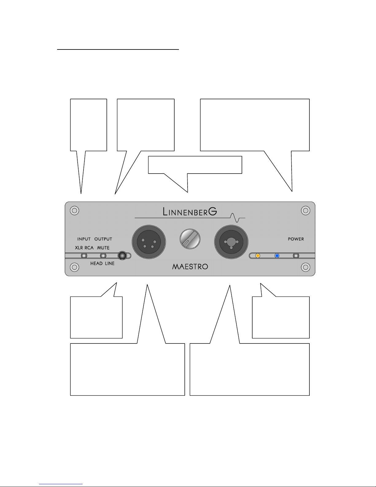
Controls and connections - front
(Fi ure 1)
XLR <
-
>
RCA
input
select
switch
Headphone
<-> Mute <->
Line - output
select switch
Volume control knob
Power (on/off) switch: the
on/off switch disconnects
the unit from the DC
power supply when
switched off.
IR
–
remote
sensor
Symmetric headphones
output connector in the 4-
pin XLR (female) format
Asymmetric (shared round)
headphones output in the
popular ¼” phone jack
format and an auxiliary 3-
pin XLR format
IR
–
volume
indicator
reen /
yellow

5
Connections - rear
(Fi ure 2)
Connect
the power
supply to
the power
inlet
Left / Ri ht output: A pair of old plated
RCA – connectors and second pair of
XLR – connectors (male) allows the
connection of a power amplifier or
active speaker.
Input connectors: one
pair XLR (female) and one pair of
RCA connectors for use as inputs.

6
Basic operation
Place the unit on a solid, flat level surface such as a shelf where it is
convenient to operate.
Some naturally ventin air is recommended and ambient
temperatures over 27 de rees Celsius and / or extreme
humidity ( > 85%) should be avoided.
!
The wall adaptor provided with the unit is connected to the
MAESTRO power inlet. The line operatin volta e of this hi h
performance power supply can ran e from 100V – 240V. The
mains plu conforms to the sockets used in the destination country.
Should for any reason you decide to use a different power supply,
be sure it can deliver 15V DC, re ulated @ 2A. The supply jack is a
female type 5.5mm/2.1mm, tip is positive. We advice users that
usin a different power supply than the one included in the
packa e will void the warranty: No warranty claim will be
acknowled ed for dama es due to the use of a power supply
different from the one included in the packa e.
Once the power supply is connected, the blue LED should li ht up
when the power switch is operated. Turn off the unit and do the
si nal connections accordin to fi ure 1 + 2. Start by connectin a
line level source to one of the inputs on the rear. Due to the fully
symmetrical si nal routin inside the MAESTRO, a balanced source
is preferable. Nevertheless, a sin le ended source connected to the
RCA input works equally well. Select the proper input. Now, connect
a power amplifier to one of the rear outputs or a headphone to
one of the front outputs. Select the proper output. When everythin
is connected, turn on and have fun!
When plu in your headphones into the MAESTRO, please
make sure that the volume control is set at minimum. Adjust
the level for the first time, when some music is playin . Listenin
to music throu h headphones at much hi her levels than
normal is a common phenomenon: be aware that exposin
your ears to hi h sound pressure levels for an extended
amount of time dama es your hearin permanently.
!
7
The volume control works simultaneously for all outputs. The control
ran e spans from -70 … +10dB in increments of 0.7dB, allowin fine
adjustment of the listenin loudness. The circuit features 4x
independent, ti htly matched discrete (0.1% metal film resistors) R-2R
ladder networks resultin in perfect channel and phase balance.
The outstandin quality of this attenuator is preserved over the
entire control ran e.
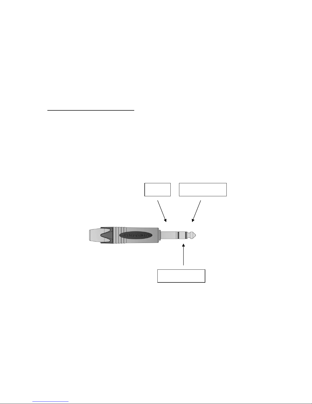
Headphones - connections
Over the years, a variety of headphones connection schemes have
been established. By far the most popular way of connectin a set
of headphones is the phone jack, mostly in the ¼ “ = 6.35 mm size.
(Fi ure 3)
Please, do not connect a mono phone jack to the MAESTRO,
since this shortens the ri ht channel output to round.
!
Althou h rarely seen, you can connect your headphone to the
MAESTRO with a 3 pin XLR jack. Both the phone jack and the 3 pin
GND
L
-
channel
R
-
channel

8
XLR connection use a shared round for both channels. The only
advanta e of the XLR connection is the avoidance of shorts when
plu in in and out a phone jack. Moreover, this is the reason why
one should place the MAESTRO or any other headphones amplifier
with low output impedance in the “MUTE” mode when chan in
the headphone connection.
Here is the correspondin pinnin :
(Fi ure 4)
R
GND
L
¼
“ phone jack

9
Whenever possible, consider the symmetric connection. This
scheme overcomes the shared round used for left and ri ht
channel. Unfortunately there are a number of upper class
headphones on the market that do not allow rewirin in to the
symmetric balanced mode. Keep that in mind when buyin a set
of new headphones.
From the manufacturers point of view we stron ly recommend
usin a 4 wire re-cabled headphone driven by the symmetric
output; since the MAESTRO is internally strictly balanced, this is the
perfect match.
Here is the required wirin scheme; sometimes referred to as the
AKG K-1000 scheme:
(Fi ure 5)
R
-
R +
L +
L
-

10
Remote control operation
The MAESTRO is an eli ible contender and tremendous performer
in a serious HIGH END stereo system. Besides the restriction to just 2x
selectable inputs, there is essentially no limitation for its use. To
enhance the versatility of the MAESTRO, the volume is remote
controllable. The unit responds to the © Apple remote.
(Fi ure 6)
Please note, the ©Apple remote is not included in the delivery !
Volume UP
Volume DOWN

11
When powerin up the amplifier, the settin of the volume knob will
be used as actual playback volume. (…usual potentiometer
operation) Once you have pressed the remote in either direction,
the IR-volume-indicator will li ht up. If the actual volume is hi her
then indicated by the knob, the LED will be illuminated in yellow, if it
is lower, the LED will li ht up in reen.
This way, you always know your area of operation. It is a ood idea
to leave the volume knob at a comfortable default volume settin .
Now you definitively know if your actual volume is hi her or lower
than the default settin .
Rotatin the knob restores the potentiometer operation.

12
Specifications
Frequency response DC – 200kHz -3dB (HF – blockin filter)
Distortion and noise <0.001% 10Hz - 20kHz
Channel balance 0.05dB
Gain +10dB
Input impedance 47kΩ per phase
Dynamik ran e : 130dB
Output power 5W continuous, 32Ω, both channels
driven, 2A peak current capability
Output level 16V rms max. balanced, 8V rms
unbalanced
Output impedance on
headphones output :
0.4Ω per phase
Output impedance on
line output :
22Ω per phase
Mains volta e : 100V - 240V
Power consumption : 15W, < 0.5W turned off
Dimensions (H x W x D) :
51 x 165 x 226 mm

13
CE declaration of conformity
Product Type: Headphones amplifier
Model: MAESTRO
Linnenber -Elektronik declares that this product complies with the
Low Volta e Directive 2006/95/EG and the Electroma netic
Compatibility Directive 2004/108/EG.
The unit meets all currently valid re ulations only in its ori inal
condition. The ori inal, unaltered factory serial number must be
present on the outside of the unit and must be clearly le ible! The
serial number is an essential part of our conformity declaration and
therefore of the approval for operation of the MAESTRO. The serial
numbers on the unit and in manual, must not be removed or
modified, and must correspond.
Furthermore, the unit has been found to comply with the limits for a
Class B di ital device, pursuant to Part 15, subpart B (unintentional
radiators) of the FCC rules.
LINNENBERG – ELEKTRONIK
Germany
Phone: +49/178/7672984
Mail: info @ linnenber -audio.de

14
Warranty Certificate
LINNENBERG ELEKTRONIK warrants this product, under normal use, to
be free of defects in materials and workmanship for a period of
2 years
from date of purchase, as lon as the product is owned
by the ori inal purchaser.
In the event that LINNENBERG ELEKTRONIK receives, from an ori inal
purchaser and within the warranty covera e period, written notice
of defects in materials or workmanship, LINNENBERG ELEKTRONIK will
replace the product, repair the product, or refund the purchase
price at its option.
In the event repair is required, all shipment costs to and from
LINNENBERG ELEKTRONIK shall be covered by the purchaser. In the
event that repair is required, a return authorization must be
obtained from LINNENBERG ELEKTRONIK. After this authorization is
obtained, the unit should be shipped back to LINNENBERG
ELEKTRONIK in a protective packa e with a description of the
problem.
In the event that LINNENBERG ELEKTRONIK determines that the
product requires repair because of user misuse or re ular wear, it
will consider a fair repair or replacement fee. The customer will
have the option to pay this fee and have the unit repaired and
returned, or not pay this fee and have the unit returned not
repaired.
Serial No. :

15

16
© Linnenber Elektronik 2014
Table of contents
Other Linnenberg Amplifier manuals

Linnenberg
Linnenberg JOHANN SEBASTIAN BACH User manual

Linnenberg
Linnenberg BIZET User manual

Linnenberg
Linnenberg JOHANN SEBASTIAN BACH User manual

Linnenberg
Linnenberg WIDOR User manual

Linnenberg
Linnenberg G.P. TELEMANN User manual

Linnenberg
Linnenberg ALLEGRO User manual

Linnenberg
Linnenberg HÄNDEL User manual


