Linortek iTrixx-Ultra 300 User manual


2

3
Contents
LINORTEK ONE-YEAR LIMITED WARRANTY.............................................................................................................................5
End-User License Agreement for Linortek Software and Documentation .............................................................................7
Getting Started........................................................................................................................................................................ 9
Activate the Meter............................................................................................................................................................10
Wiring the Server ..............................................................................................................................................................10
Board Layout Reference....................................................................................................................................................10
Power Connection.............................................................................................................................................................11
Network Connection.........................................................................................................................................................11
Relay Connection ..............................................................................................................................................................11
Voltage Output Connection ..............................................................................................................................................12
Digital Input Connection ...................................................................................................................................................12
Analog Input Connection ..................................................................................................................................................12
Accessing the SERVER ...........................................................................................................................................................13
Finding your IP Address with Linortek Discoverer............................................................................................................13
Finding the IP address by connecting to USB port on Your PC.........................................................................................14
Connecting your SERVER directly to Your PC....................................................................................................................14
Software Configuration.........................................................................................................................................................15
Landing Page.....................................................................................................................................................................15
Home.................................................................................................................................................................................15
Services .............................................................................................................................................................................16
In/Out Page...................................................................................................................................................................16
Hours Page ....................................................................................................................................................................22
Tasks..................................................................................................................................................................................23
Set Schedule Page.........................................................................................................................................................23
Logs ...................................................................................................................................................................................26
Settings..............................................................................................................................................................................27
User and Admin Credentials Page.................................................................................................................................27
Time/Date Page.............................................................................................................................................................27
Settings Page.................................................................................................................................................................28
Configure...........................................................................................................................................................................29
Dynamic DNS Page........................................................................................................................................................29
Email Setup Page...........................................................................................................................................................30
MQTT Setup Page..........................................................................................................................................................30
Network Configuration Page.........................................................................................................................................31
IP Range Configuration Page.........................................................................................................................................32
Remote Devices Page....................................................................................................................................................32

4
System...............................................................................................................................................................................33
Load/Reboot System Page............................................................................................................................................33
Data Collection......................................................................................................................................................................35
Hour Collector App............................................................................................................................................................35
DataCollector Pro App ......................................................................................................................................................35
RESTful API........................................................................................................................................................................35
MQTT.................................................................................................................................................................................35
JSON file ............................................................................................................................................................................35

5
LINORTEK ONE-YEAR LIMITED WARRANTY
Consumer law: For consumers who are covered by consumer protection laws or regulations in their country of residence (“Consumer Law”), the benefits provided in
this Linortek One-Year Limited Warranty (“Linortek Limited Warranty”) are in addition to and not instead of the rights provided by Consumer Law and it does not
exclude, limit or suspend your rights arising from Consumer Law. You should consult the proper authorities in your country of residence for further information about
these rights
.
Linortek’s warranty obligations for this hardware product (“Product”) are limited to the terms set forth below:
Linor Technology, Inc. (“Linortek”) warrants this product against defects in materials and workmanship for a period of ONE (1) YEAR from the date of retail purchase
by the original end-user purchaser (“Warranty Period”) when used in accordance with the operating instructions. A copy of a retail receipt is required as proof of
purchase. If a hardware defect arises and a valid claim is received within the Warranty Period, at its option and to the extent permitted by law, Linortek will either (1)
repair the hardware defect at no charge, using new or refurbished replacement parts, (2) exchange the product with a product that is new or which has been
manufactured from new or serviceable used parts and is at least functionally equivalent to the original product, or (3) refund the purchase price of the product. When
a refund is given, the product for which the refund is provided must be returned to Linortek and becomes Linortek’s property.
The foregoing warranty is subject to Buyer’s (i) prompt written claim and (ii) timely provision to Linortek of an opportunity to inspect and test the Product claimed to
be defective. Such inspection may be on Buyer’s premises and/or Linortek may request the return of the Product at Buyer’s expense. However, Linortek shall not be
responsible for packing, inspection, or labor costs in connection with the return of Product. No Product shall be accepted for warranty service that is not accompanied
by a Return Merchandise Authorization number (RMA#) issued by Linortek.
EXCLUSIONS AND LIMITATIONS
This Limited Warranty excludes damage resulting from abuse, misuse, neglect, fire or other external causes, accident, modifications, repairs or other causes that are
not defects in materials and workmanship. Software distributed by Linortek with or without the Linortek brand name including, but not limited to system software
(“Software”) is not covered under this Limited Warranty. Your use and rights associated with the Software are governed by the Linortek End User License Agreement
which you can find here: https://www.linortek.com/end-user-license-agreement/. Linortek is not responsible for damage arising from failure to follow instructions
relating to the product’s use. To assure conformance with operating limitations, Buyer should refer to the instruction manual [provided with the product]. Batteries
are not included in the Warranty.
TO THE MAXIMUM EXTENT PERMITTED, THIS LIMITED WARRANTY AND THE REMEDIES SET FORTH ABOVE ARE EXCLUSIVE AND IN LIEU OF ALL OTHER
WARRANTIES, REMEDIES, AND CONDITIONS, AND LINORTEK SPECIFICALLY DISCLAIMS ALL STATUTORY OR IMPLIED WARRANTIES, INCLUDING BUT NOT LIMITED
TO, WARRANTIES OF MERCHANTABILITY, FITNESS FOR A PARTICULAR PURPOSE, NON-INFRINGEMENT. IN SO FAR AS SUCH WARRANTIES CANNOT BE DISCLAIMED,
ALL SUCH WARRANTIES SHALL, TO THE EXTENT PERMITTED BY LAW, BE LIMITED IN DURATION TO THE DURATION OF THE LINORTEK LIMITED WARRANTY AND THE
REMEMDY SHALL BE LIMITED TO REPAIR, REPLACEMENT OR REFUND AS DETERMINED BY LINORTEK IN ITS SOLE DISCRETION. SOME STATES (COUNTRIES AND
PROVINCES) DO NOT ALLOW LIMITATIONS ON HOW LONG AN IMPLIED WARRANTY OR CONDITION MAY LAST, SO THE LIMITATIONS DESCRIBED ABOVE MAY NOT
APPLY TO YOU. THIS WARRANTY GIVES YOU SPECIFIC LEGAL RIGHTS, AND YOU MAY ALSO HAVE OTHER RIGHTS THAT VARY FROM STATE TO STATE (OR BY
COUNTRY OR PROVINCE). THIS LIMITED WARRANTY IS GOVERNED BY AND CONSTRUED UNDER THE LAWS OF THE UNITED STATES.
Disclaimers
1. Read Instructions –Read all the safety and operating instructions before operating the product.
2. Retain Instructions –Retain the safety and operating instructions for future reference.
3. Heed Warnings –Adhere to all warnings on the product and in the operating instructions.
4. Follow Instructions –Follow all operating and use instructions.
5. Cleaning –Unplug the product from power before cleaning. Do not use liquid cleaners or aerosol cleaners. Use a damp cloth for cleaning the enclosure
only.
6. Attachments –Do not use attachments unless they are specifically recommended by Linortek. Using incompatible or otherwise unsuitable attachments
can be hazardous.
7. Accessories –Do not place this product on an unstable stand, tripod, bracket, or mount. The product may fall, causing serious injury to a person and
serious damage to the product. Use only with a stand, tripod, bracket, or mount recommended by the manufacturer, or sold with the product. Follow the
manufacturer’s instructions when mounting the product, and only use mounting accessories recommended by the manufacturer. Be cautious when using
an appliance and cart combination. Quick stops, excessive force, and uneven surfaces may cause the appliance and cart combination to overturn.
8. Ventilation –Openings in the enclosure, if any, are provided for ventilation and to ensure reliable operation of the product and to protect it from
overheating. Do not block or cover these openings. Do not place this product in a built-in installation unless proper ventilation is provided or the Linortek’s
instructions have been adhered to.
9. Power Sources –Operate this product only from the power source type indicated in the instruction manual or on the product label. If you are not sure of
the type of power supply you plan to use, consult your appliance dealer or local power company –provided that use of any power source type other than
indicated in the instruction manual or marking label will void any warranty. For products intended to operate from battery power, or other sources, refer
to the operating instructions [included with the product].
10. Grounding or Polarization –This product may be equipped with a polarized alternating-current line plug (a plug having one blade wider than the other).
This plug will fit into the power outlet only one way. This is a safety feature. If you are unable to insert the plug fully into the outlet, try reversing the plug.
If the plug still fails to fit it is because your outlet is incompatible with the plug. Contact your electrician to replace your outlet with one that is compatible.
Do not force the plug to fit into an incompatible outlet or otherwise try to defeat the safety purpose of the plug. Alternately, this product may be equipped
with a 3-wire grounding-type plug, a plug having a third (grounding) pin. This plug will only fit into a grounding-type power outlet. This is a safety feature.
Do not force the plug to fit into an incompatible outlet or otherwise try to defeat the safety purpose of the plug. If your outlet is incompatible with the
plug, contact your electrician to replace your outlet with one that is compatible.
11. Power-Cord Protection –Route power supply cords so that they are not likely to be walked on or pinched by items placed upon or against them, paying
particular attention to cords and plugs, convenience receptacles, and the point where the cords exit from the appliance.
12. Power Lines –Do not place an outdoor system anywhere in the vicinity of overhead power lines or other electric light or power circuits, or where it can fall
into such power lines or circuits. When installing an outdoor system, use extreme care to keep from touching such power lines or circuits as contact with
them might be fatal.
13. Overloading –Do not overload outlets and extension cords as this can cause fire or electric shock.
14. Object and Liquid Entry –Never push objects of any kind into this product through openings as they may touch dangerous voltage points or short-out parts
which can cause fire or electric shock. Never spill liquid of any kind on the product.
15. Servicing –Do not attempt to service to this product yourself as opening or removing covers may expose you to dangerous voltage or other hazards. Refer
all servicing of the product to Linortek.
16. Damage Requiring Service –Unplug the product from the outlet and refer servicing to Linortek Customer Support under the following conditions:

6
a. When the power-supply cord or plug is damaged.
b. If liquid has been spilled, or objects have fallen onto the product.
c. If the product has been exposed to rain or water.
d. If the product does not operate normally by following the operating instructions [included with the product]. Adjust only those controls that are
covered by the operating instructions, as an improper adjustment of other controls may result in damage and will often require extensive work
by a qualified technician to restore the product to its normal operation.
e. If the product has been dropped or the cabinet has been damaged.
f. If the product exhibits a distinct change in performance.
17. Replacement Parts –If replacement parts are necessary, have a Low-Voltage Electrician replace them using only part specified by the manufacturer.
Unauthorized substitutions may result in fire, electric shock or other hazards. Replacement parts can be found at https://www.linortek.com/store/
18. Safety Check –Upon completion of any service or repairs to this product, ask the service technician to perform safety checks to determine that the
product is in proper operating condition.
19. Coax Grounding –If an outside cable system is connected to the product, be sure the cable system is grounded. U.S.A. models only–Section 810 of the
National Electrical Code, ANSI/NFPA No.70-1981, provides information with respect to proper grounding of the mount and supporting structure, grounding
of the coax to a discharge product, size of grounding conductors, location of discharge product, connection to grounding electrodes, and requirements for
the grounding electrode.
20. Lightning –For added protection of this product during a lightning storm, or before leaving it unattended and unused for long periods of time, unplug it
from the wall outlet and disconnect the cable system. This will prevent damage to the product due to lightning and power-line surges.
21. Outdoor Use –This product is not waterproof and should not be allowed to get wet. Do not expose to rain or other types of liquid. Do not leave out-of-
doors overnight as condensation may occur.
22. While changing batteries, fuses or handling a board level product be careful of electrostatic discharge which can damage electronic devices. It is best to
use a grounded electronics service bench. If this is not available you can discharge yourself by touching a metal appliance or pipe. While changing the
batteries or fuses do not touch i) any wires other than the battery wires and ii) the printed circuit board.
LIMITATION OF LIABILITY
IN NO EVENT WILL LINOR TECHNOLOGY BE LIABLE, WHETHER IN CONTRACT, TORT, OR OTHERWISE, FOR ANY INCIDENTAL, SPECIAL, INDIRECT, CONSEQUENTIAL OR
PUNITIVE DAMAGES, INCLUDING, BUT NOT LIMITED TO, DAMAGES FOR ANY LOSS OF USE, LOSS OF TIME, INCONVENIENCE, COMMERCIAL LOSS, OR LOST PROFITS,
SAVINGS, OR REVENUES TO THE FULL EXTENT SUCH MAY BE DISCLAIMED BY LAW.
DISCLAIMER FOR CRITICAL APPLICATIONS
This product is not intended or authorized for life support product or for other uses for which a failure could cause personal injury or death. If you or your customers
use or permit the use of this product for such unintended or unauthorized uses, you agree to fully indemnify Linor Technology and its affiliates, and the officers,
employees and distributors of each, from all liability related to such use, including attorneys’ fees and costs.
FURTHER NOTICE FOR LIMITATION OF USE
Unless specifically stated, our Products are NOT designed to switch line voltage (110V and above) devices. To control device that operate at line voltages a qualified
electrician MUST install an intermediary device such as a relay. When choosing devices to control, it is best to select low voltage controls such as a 24VAC solenoid to
water flow control. Only qualified electricians may wire a line voltage device. Additionally, local codes must be followed including but not limited to wire gauge size
and suitable housing. Linortek assumes no responsibility for harm to the user or third parties for improperly using our Products. This liability remains with the user.
Linortek assumes no responsibility for damage to the device due to improperly using our Products.
RELAY VOLTAGE SPECIFICATIONS
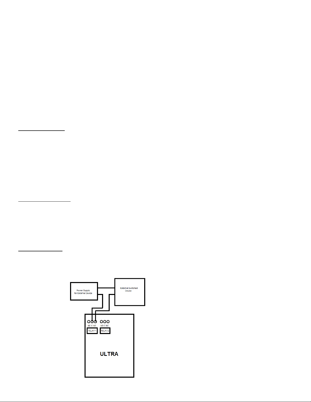
Please use caution when connecting devices to electrical circuits or other equipment. This web controller is NOT designed to connect to any voltage greater than 48V.
If you want the product to control Line Voltage products and devices, refer to Diagram 1 below. Utilizing this arrangement, should allow you to virtually control
anything. It is important that you use licensed electricians and comply with electrical codes that are applicable to your location. These codes exist for your safety, as
well as the safety of others. Linortek assumes no responsibility for any harm or damage resulting from a failure adhere to local laws, ordinances or regulations or
failure to follow specified instructions for installation and product usage.

7
End-User License Agreement for Linortek Software and Documentation
This End-User License Agreement (“EULA”) is a legal agreement between YOU (an individual or single entity) and Linor Technology, Inc. (“Linortek” or “we” or “us”)
that governs your use of the software and documentation (“Software”) embedded in or associated with the Fargo, Koda, Netbell, IoTMeter, and iTrixx series of
products (“Linortek Products”).
This EULA does not govern your use of the Linortek website or the Linortek Products (excluding the Software). Your use of the Linortek website is governed by the
Linortek website terms of service and the Linortek privacy policy which can be found at: http://www.linortek.com/terms-and-conditions [Your purchase of Linortek
Products (excluding the Software) is governed by the Linortek limited warranty, which can be found at https://www.linortek.com/linortek-one-year-limited-warranty/
This EULA governs your access and use of the Software. This EULA gives you specific legal rights, and you may also have other legal rights in addition, which vary from
jurisdiction to jurisdiction. The disclaimers, exclusions, and limitations of liability under this EULA will not apply to the extent prohibited or limited by applicable law.
Some jurisdictions do not allow the exclusion of implied warranties or the exclusion or limitation of incidental or consequential damages or other rights, so those
provisions of this EULA may not apply to you.
By installing, accessing, copying and/or using the Software or documentation you are agreeing to be bound by the terms and conditions of this EULA on behalf of
yourself or the entity that you represent in connection with such installation, access, copying and/or use. You represent and warrant that (i) you have the right,
authority, and capacity to accept and agree to the terms of this EULA on behalf of yourself or the entity you represent (ii) you are of sufficient legal age in your
jurisdiction of residence, (iii) you are not located in a country that is subject to a U.S. Government embargo, or that has been designated by the U.S. Government as a
“terrorist supporting” country; and (ii) you not listed on any U.S. Government list of prohibited or restricted parties.
If you do not wish to be bound by the terms of this EULA you may not install, access, copy or use the Software in any way (whether or not pre-installed on a device
you have purchased).
1. Permitted Use of Software/ Software License.
Subject to the terms of this EULA, Linortek grants you a limited, revocable, non-exclusive, non-sublicensable, non-transferable right and license to (a) download,
install and execute one copy of the Software, in executable object code form only, solely on the Linortek Product that you own or control and to (b) use the Software
solely in connection with the Linortek Product in accordance with its intended use as described on the Linortek website (each of 1(a) and 1(b) a “Permitted Use” and
collectively “Permitted Uses”).
2. Restrictions on Your Use of the Software.
You agree not to, and not to permit others to, use the Software for any purpose other than the Permitted Uses described in Section 1 above. This means, among
other things, you may not:
(a) edit, alter, modify, adapt, translate, make derivative works of, disassemble, reverse engineer or reverse compile any part of the Software (except to the
extent applicable laws specially prohibit such restriction for interoperability purposes, in which case you agree to first contact Linortek and provide
Linortek an opportunity to create such changes as are needed for interoperability purposes);
(b) license, assign, distribute, transmit, sell, rent, host, outsource, disclose or otherwise use the Software for any commercial purpose or make Software
available to any third party;
(c) allow any third party to use the Software on behalf of or for the benefit of any third party;
(d) use any portion of the Software on any device or computer other than the Linortek Product that you own or control;
(e) use the Software in any way that breaches any applicable local, national or international law; or
(f) remove or alter any labels, symbols, legends or proprietary notices, including but not limited to any copyright, trademark, logo in the Software. You may
not disclose the results of any performance or functional evaluation of any of the Software to any third party without the prior written consent of Linortek
for each such release.
3. Updates.
Linortek may from time to time develop updates, upgrades, patches, bug fixes and other modifications (“Updates”) to improve the performance of the Software.
Except as otherwise provided on the Linortek website, these Updates will be provided to you free of charge. These Updates may be automatically installed without
notice to you. By using the Software, you also consent to automatic Updates. If you do not agree to this you may not install, access, copy or use the Software in any
way.
4. Ownership.
The Software is licensed to you and not sold. Linortek reserves all rights to the Software and any Updates not expressly granted herein. The Software and Linortek
Products are protected by copyright, trademark and other intellectual property laws and treaties. Linortek and its licensors own the title, copyright, trademarks and
other intellectual property rights in the Software. You are not granted any rights to Linortek’s trademarks or service marks. There are no implied licenses in this EULA.
5. Termination.
This EULA is effective from the date you first use the Software and will continue for as long as you own the Linortek Product associated with it or until you or Linortek
terminate this agreement under this section. You may terminate this EULA at any time upon written notice to Linortek at the address provided below. Linortek may
terminate this EULA at any time if you fail to comply with any of the terms in this agreement. The license granted in this EULA terminates immediately when the
agreement terminates. Upon termination, you must stop using the Linortek Product and the Software and you must delete all copies of the Software. The terms of
Sections 2 will still remain in effect after the agreement terminates.
6. Warranty Disclaimer.
EXTENT PERMITTED BY APPLICABLE LAW, LINORTEK PROVIDES THE SOFTWARE “AS-IS” AND DISCLAIMS ALL WARRANTIES AND CONDITIONS, WHETHER EXPRESS,
IMPLIED, OR STATUTORY, INCLUDING THE WARRANTIES OF MERCHANTABILITY, FITNESS FOR A PARTICULAR PURPOSE, TITLE, QUIET ENJOYMENT, ACCURACY, AND
NON-INFRINGEMENT OF THIRD-PARTY RIGHTS. LINORTEK DOES NOT GUARANTEE ANY SPECIFIC RESULTS FROM THE USE OF THE SOFTWARE. LINORTEK MAKES NO
WARRANTY THAT THE SOFTWARE WILL BE UNINTERRUPTED, FREE OF VIRUSES OR OTHER HARMFUL CODE, TIMELY, SECURE, OR ERROR-FREE. YOU USE THE
SOFTWARE AND THE LINORTEK PRODUCT AT YOUR OWN DISCRETION AND RISK. YOU WILL BE SOLELY RESPONSIBLE FOR (AND LINORTEK DISCLAIMS) ANY AND ALL
LOSS, LIABILITY, OR DAMAGES RESULTING FROM YOUR USE OF THE SOFTWARE AND LINORTEK PRODUCT.
7. Limitation of Liability.
Nothing in this EULA and in particular within this “Limitation of Liability” clause shall attempt to exclude liability that cannot be excluded under applicable law.
TO THE MAXIMUM EXTENT PERMITTED BY APPLICABLE LAW, IN ADDITION TO THE ABOVE WARRANTY DISCLAIMERS, IN NO EVENT WILL (A) LINORTEK BE LIABLE FOR
ANY CONSEQUENTIAL, EXEMPLARY, SPECIAL, OR INCIDENTAL DAMAGES, INCLUDING ANY DAMAGES FOR LOST DATA OR LOST PROFITS, ARISING FROM OR RELATING
TO THE PRODUCTS OR SOFTWARE, EVEN IF LINORTEK KNEW OR SHOULD HAVE KNOWN OF THE POSSIBILITY OF SUCH DAMAGES, AND (B) LINORTEK’S TOTAL
CUMULATIVE LIABILITY ARISING FROM OR RELATED TO THE PRODUCTS AND SOFTWARE, WHETHER IN CONTRACT OR TORT OR OTHERWISE, SHALL BE LIMITED TO AN
AMOUNT NEVER TO EXCEED THE AMOUNT ACTUALLY PAID BY YOU TO LINORTEK AND LINORTEK’S AUTHORISED DISTRIBUTOR OR SALES REPRESENTATIVE FOR THE
PRODUCTS OR SERVICES AT ISSUE IN THE PRIOR 6 MONTHS (IF ANY). THIS LIMITATION IS CUMULATIVE AND WILL NOT BE INCREASED BY THE EXISTENCE OF MORE
THAN ONE INCIDENT OR CLAIM. LINORTEK DISCLAIMS ALL LIABILITY OF ANY KIND OF LINORTEK’S LICENSORS AND SUPPLIERS.
8. Compliance with Export Laws.
You acknowledge that the Software and related technology are subject to U.S. export control laws U.S. export jurisdiction and may be subject to export or import
regulations in other countries. You agree to strictly comply with all applicable international and national laws and regulations that apply to the Software, including the
U.S. Export Administration Regulations as well as end-user, end-use, and destination restrictions issued by U.S. and other governments. You acknowledge that you

8
have the responsibility to obtain authorization to export, re-export, or import the Software and related technology, as may be required. You will indemnify and hold
Linortek harmless from any and all claims, losses, liabilities, damages, fines, penalties, costs and expenses (including attorney’s fees) arising from or relating to any
breach by you of your obligations under this section.
9. Assignment.
You may not assign any of your rights or obligations under this EULA, and any attempt to assign will be void and without effect.
10. Notices.
Linortek may provide any notice to you related to this EULA using the email and address that you provided when you registered with Linortek.
11. Waiver
To be effective, any and all waivers by Linortek hereunder must be in writing and signed by an authorized Linortek representative. Any other failure of Linortek to
enforce any term hereunder will not be deemed a waiver.
12. Severability.
Any provision of this EULA that is found to be unenforceable will be edited and interpreted to accomplish the objectives of that provision to the greatest extent
possible under applicable law and all remaining provisions will remain in full force and effect.
13. Governing Law; Venue.
You agree that this EULA, and any claim, dispute, action, cause of action, issue, or request for relief arising out of or relating to this EULA, will be governed by the laws
of the state of North Carolina, U.S.A., without regard to conflicts of laws principles, provided that if you reside in a country that will not apply U.S. law to disputes
related to these terms, then the laws of your country will apply. You also agree that the United Nations Convention on Contracts for the International Sale of Goods
shall not apply. You agree that regardless of any statute or law to the contrary, any cause of action against us arising out of or related to the Linortek website, the
Software or the Linortek Products must commence within one (1) year after the cause of action accrues or such cause of action shall be permanently barred. Any
action or proceeding relating to this EULA must be brought in a federal or state court located in Raleigh, North Carolina and each party irrevocably submits to the
jurisdiction and venue of any such court in any such claim or dispute, except that Linortek may seek injunctive relief in any court having jurisdiction to protect its
intellectual property.
This Product may expose you to traces of chemicals including lead which is known to the state of California to cause cancer or
birth defects or other reproductive harm. For more information, visit www.p65warnings.ca.gov

9
Getting Started
Thank you for purchasing the Linortek ITrixx-Ultra 300. The Ultra 300 is an IoT controller and run-time meter. The Ultra 300 is
equipped with two meters on the software that you can use to track equipment usage or uptime/downtime or as a counter.
The Ultra 300 is the latest development of Linortek web-enabled I/O controller with MQTT protocol, hardware-based encryption,
supports HTTPS connections, encrypted email servers, CAN interface, increase in RAM and FLASH memories.
The Ultra 300 is equipped with two digital inputs (5-24VDC), two analog inputs (AC), two relay outputs, CAN interface and built-in
web-based software. All of our controllers come complete with all parts and software necessary for installation, operation and
ability to control the devices attached to it. Upon arrival, please inspect the contents of the box to ensure that your kit is complete
and contains all necessary components.
The iTrixx-Ultra 300 will be referred to as SERVER, and the hour meter as METER hereafter. When there are differences or additional
features they will be noted in the text.
For instructional videos, FAQ’s and contact information for our technical support team, please visit:
https://www.linortek.com/technical-support
PRODUCT CHECKLIST –Each product kit box contains the following:
____One iTrixx-Ultra 300 SERVER
____One 12VDC Power Supply
____Micro USB to 12V Jack
____One CAT5 Patch Cord
____One DIN Rail Mount Clip
____iTrixx-Ultra 300 Quick Setting Instruction
____One 2.2k OMETER Resistor Kit
The SERVER is designed to be integrated into existing equipment. Installing your SERVER will involve tapping circuits on the
equipment you intend to monitor.
IN NO EVENT WILL LINOR TECHNOLOGY BE LIABLE, WHETHER IN CONTRACT, TORT, OR OTHERWISE, FOR ANY
INCIDENTAL, SPECIAL, INDIRECT, CONSEQUENTIAL OR PUNITIVE DAMAGES, INCLUDING, BUT NOT LIMITED TO,
DAMAGES FOR ANY LOSS OF USE, LOSS OF TIME, INCONVENIENCE, COMMERCIAL LOSS, OR LOST PROFITS,
SAVINGS, OR REVENUES TO THE FULL EXTENT SUCH MAY BE DISCLAIMED BY LAW.
FURTHER NOTICE FOR LIMITATION OF USE
Unless specifically stated, this product is NOT designed to switch line voltage devices. This limitation includes all of Linortek
products. To control device that operate at line voltages the user MUST install and intermediary device such as a relay.
When wiring a line voltage device using intermediary device, you MUST either be a qualified electrician or use the services of a
qualified electrician. Additionally, local codes must be followed including, but not limited to, wire gauge size and suitable housing.
Linortek cannot assume any responsibility for harm to the user or third parties for improperly using our Fargo product. This liability
remains with the user. Linortek cannot assume any responsibility for damage to the device for improperly using our SERVER product.

10
Activate the Meter
The iTrixx Hour Meter software has two separate hour counters with independent triggers. The hour counters may be activated in a
number of different ways.
1. In the simplest setup the METER may be activated whenever power is applied to the unit. In this case, if the SERVER is on, it is
counting. A voltage threshold is provided so the SERVER may stop counting as power is lost to prevent memory corruption. In this
way, you only need to connect the SERVER to the same power source of the equipment you wish to collect running data, no other
wiring required.
2. You may also use one of the inputs to turn counting on and off. There are two digital inputs in the SERVER. The digital inputs allow
the SERVER to detect an external on/off state of a sensor.
3. Alternatively, it can be configured to follow one of the relays such that when the relay is activated the SERVER will count. There
are two relay outputs and are simply numbered "OUT1" and "OUT2" on the SERVER. These relays are dry contact relays, normally
open/normal close options.
Most common use case is to wire a sensor to a digital input to the same power source of your SERVER to trigger the meter, so when
your equipment is on, the meter is counting.
Wiring the Server
Note: For a diagram showing the location of all connectors on your SERVER referenced in this section, please see the Board Layout
Reference below.
Board Layout Reference
11
1. Relay outputs: 2 relay outputs, signal relay, 1 Form C, 1A @ 30VDC, #2 on the left
2. Voltage output: This is used to drive external devices such as a sensor. The voltage supplied depends on what power source
is used to power the ULTRA SERVER.
3. Digital inputs: 2 digital inputs, 5VDC-48VDC (24VDC-48VDC must use the external resistor), #2 on the left
4. Analog inputs: 2 analog inputs, isolated, #2 on the left
5. CAN inputs (software not yet implemented)
6. Digital input switches: IN2 on the on the left; Up position –Pull-up (PU), Down position - Isolated (ISO)
7. Reset button
8. Reload button
9. RJ 45 connector
10. USB mini connector for temperature/humidity sensor (Sold separately)
11. Power input (12VDC-24VDC/USB(5V)
Caution: These units are ground isolated. Always connect so that power loop is only connected to the SERVER unit. Do NOT use
external ground connections. Doing so may damage the SERVER or POE originating device.
Power Connection
The SERVER power input is a Micro USB connector and marked as POWER on the enclosure. Connect the 12VDC power
supply to a suitable AC outlet and connect the barrel connector into the Micro USB connector, plus the other side of the
USB connector to the SERVER at the location labelled POWER, or you can use a USB cable to connect it to your computer
to power it on and find out the IP address from your network. Alternatively, you may also use POE. At this point the
GREEN/Boot LED should come on and start flashing indicating the SERVER is operating and is in the "Bootload Mode".
This mode allows the user to update the server software that is used on the unit. After about 5 seconds, the GREEN LED
will go off and the RED LED will start blinking once per second indicating the SERVER is operating in "Server Mode" and is
accessible on a network utilizing TCP/IP protocols.
Network Connection
Plug the Ethernet cable into the NET connector, the “Connection" LED on the Ethernet connector side will come on if you connect to
network switch and a 100MHz network is available, otherwise it will remain off and the "Activity" LED should start blinking indicating
network activity.
CAUTION: WHEN YOU USE POE NETWORK SWITCH, DO NOT USE THE 12VDC POWER SUPPLY TO POWER THE SERVER AT THE
SAME TIME, IT WILL DAMAGE THE BOARD.
Relay Connection
The SERVER has 2 signal Relays (1 Form C, 1A @ 30VDC) with push-in spring connectors and are simply numbered OUT "1" and "2".
These are dry contact relays. The Ultra 300 units are designed for only low voltage control and should not have a voltage applied to
the relay greater than 30 volts. This is for your safety as well as to stay within the parameters of the parts and circuit board design.

12
The relays have 3 terminals labelled NO, C and NC which stand for Normally Open, Common and Normally Closed. When activated,
the relay moves the connection from C-NC to C¬NO. If you want to make a connection when the relay is activated, connect your
wires between C and NO. When the relay is activated C and NO will be connected together. If you want to break a circuit when the
relay is activated, make your connections to C and NC. When the relay is activated, the circuit will be broken (or open)
Voltage Output Connection
The SERVER has a voltage output that can be used to drive external devices. The voltage depends on what power source is used to
power the ULTRA SERVER. When USB is used the voltage out is 5V, when POE is used it's 12V out, when an external power supply is
used it is the same voltage as the power supply. There is always a small voltage drop and it is limited to 50mA. This is useful when
using the output to trigger a relay, or power a sensor. For higher voltage or higher current than our internal relay can handle, wire
the positive side of your external device to the "Voltage/+" terminal, negative to "-" terminal.
Digital Input Connection
There are two digital inputs on the SERVER with push-in spring connectors, labeled as IN1 and IN2 on the enclosure. Each input has 2
terminals, marked as C A [C-cathode (-), A-anode (+)].
The digital inputs allow the SERVER to detect an external on/off state of a sensor. With this information the SERVER can display
whether an input is on or off, count events in a resettable or non-resettable counter, and calculate the frequency (such as for use as
a tachometer) or the period of the input. There are two modes of operation for the digital inputs - PULL UP and ISOLATED.
•PULL UP mode connects a 1K resistor to an internal voltage allowing you to use a simple switch (such as a magnetic door
switch) across terminals 1 and 2. This when the switch is activated a signal is sent to the input.
•ISOLATED mode allows you to directly drive the Ultra's optoisolator with an external voltage though an internal 1K resistor.
This voltage may be in the range of 5V to 24V supplying a minimum of 2mA or a maximum of 30mA to the optoisolator
diode. There is no other internal connection to this voltage so it is an isolated input.
These modes are selected by the switch on the SERVER (see Board Layout Reference), put the switch to down position for ISO and
up position for PU. These are set at the factory to ISO (down) by default.
Caution: If you intend to use isolated mode, verify input switch is set to ISO before applying an external voltage. Doing otherwise
may damage the Ultra or POE originating device.
Analog Input Connection
The analog inputs allow the SERVER to read the value of external equipment. There are 2 analog inputs on the SERVER with push-in
spring connectors, labeled as AN1 and AN2 on the enclosure. Each input has 1 terminal. To wire a 2-wire analog sensor to the server,
wire the data wire to the analog input, ground wire to GND terminal. If your analog sensor comes with 3 wires, wire the data wire to
the analog input, ground wire to GND terminal, power wire to the Voltage/+ terminal.
13
The 2 analog input terminal blocks are connected to non-isolated 0-5V current sensors which may be connected to a variety of
devices such as temperature or pressure sensors. The SERVER provides a ground and power connection so that measurements can
be made without external voltage references. You should use a sensor that is isolated so that the it makes no connection to a
remote ground.
Accessing the SERVER
Once your SERVER is powered on and connected to the network, it will automatically obtain an IP address via DHCP as long as your
router is configured to do so. To connect, enter the IP address into your web browser. This will take you to your SERVER’s landing
page. To log in, click the Log In button on the top right of the page. Your browser will prompt you to enter your username and
password. By default, these credentials are both set to admin. To find your Ultra’s IP address, see below.
Finding your IP Address with Linortek Discoverer
The Discoverer program will automatically locate your SERVER. The Discoverer is a Java program, and requires Java Runtime to be
installed to use this feature. Java can be found here: http://java.com/en/download/index.jsp.
To download the Discover program, please go to: https://www.linortek.com/downloads/support HYPERLINK
"https://www.linortek.com/downloads/supportprogramming/"programming/
Use of Chrome & Firefox browsers is recommended. Please note: If you prefer to use Internet Explorer, Internet Explorer saves
Linortek Discoverer as a Zip file by default. In order to use the Discoverer, you will need to select Save as and rename the file as
Linortek Discoverer.jar when you download.
When downloading the Discover program, sometimes you will see a popup warning message depending on your browser security
settings, asking if you want to keep or discard this file, please click the Keep button as this is a Java program, it won't harm your
computer.
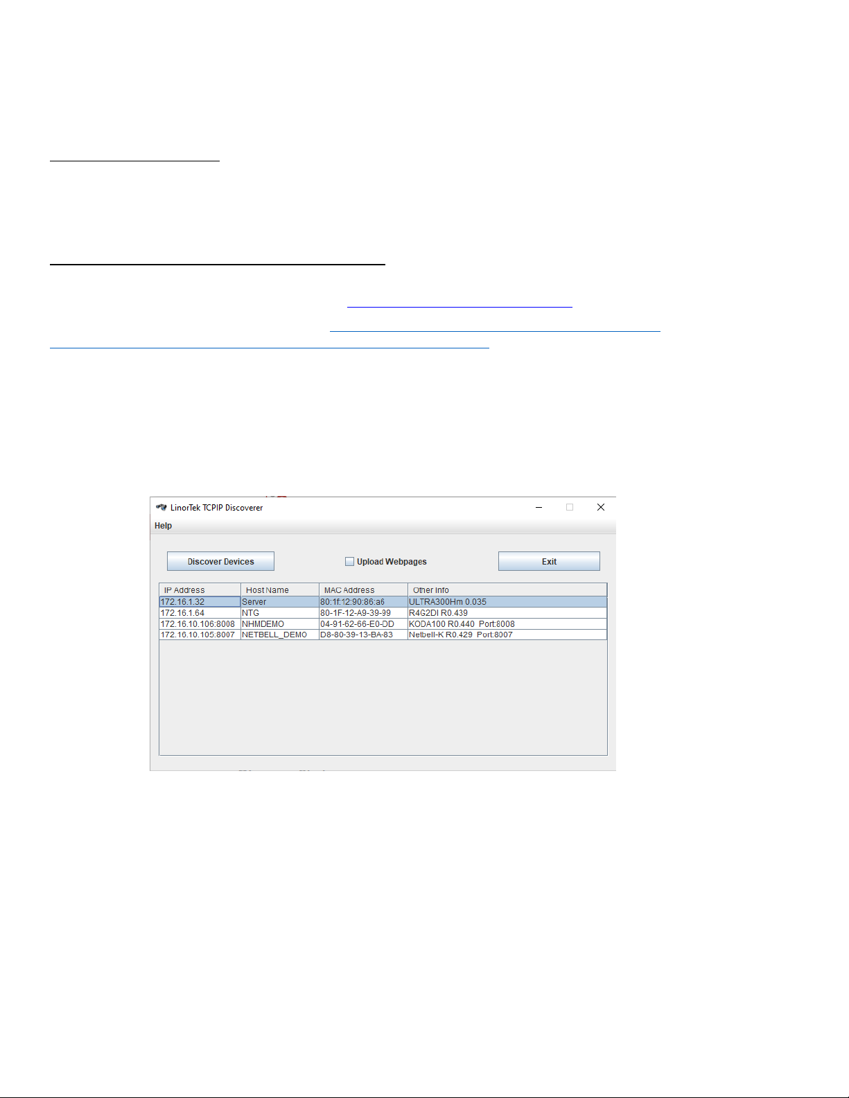
Once Discoverer locates your device, it will display:
•IP Address
•Host Name
•MAC Address
•Other Info:
•Blue LED (if it’s ON)
•Product name
•Server Software Revision
•Port Number (If ported)
14
Click the device you want to use shown on the Discoverer program to launch the SERVER’s web pages in your browser. Click the
Login button on the homepage. Default username/password is: admin/admin. You may change these as you desire or disable this
feature in the settings menu.
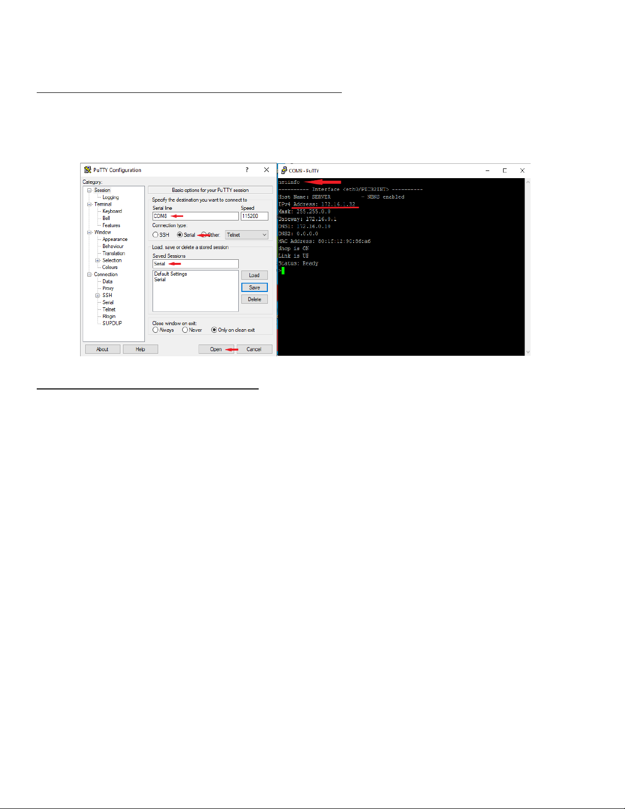
Finding the IP address by connecting to USB port on Your PC
If there is no way to run The Discoverer app you can find the SERVER’s IP address using any terminal emulator. Connect your SERVER
to the USB port on your PC using Device’s ‘POWER’ input. Open any terminal emulator you prefer and set your COM port to Serial
(You can find your COM port number under Device Manager), open the window and type netinfo command. You will get your Ultra’s
IP address.
Connecting your SERVER directly to Your PC
You can also plug your SERVER directly to your PC in the case there is no network connection available. If you plug your SERVER to
your PC’s Ethernet port it will use the default IP address: 169.254.1.1 unless you have previously configured your SERVER to use a
static IP. Enter 169.254.1.1 into your web browser to connect. No internet connection required. Once configured, you can then
install your Ultra 300 where desired.

15
Software Configuration
Landing Page
Once you have entered the IP address and port number, if set, the Landing page will open. This page shows the SERVER name of this
server which you may change in Configure/Network Config page.
This page is static with no background activity and is a useful place to park if you are not using the SERVER and do not
want to close the connection.
The Ultra 300 has a different landing page from most Linortek devices. In addition to the normally displayed information, this page
also displays the data from each of the two meters on your device.
By pressing LOGIN, you will be asked for your username and password (default username and password: admin/admin). These
credentials will be retained by the browser until the browser is closed. You can disable the password requirement in Settings –User
and Admin Credentials page.
The landing page displays the following settings:
•Two meters: Each Ultra 300 includes two separate hour meters with independent triggers.
•Each meter can record 999999.99 hours, decimal hours with 1/100 hour (you can change it for 1/10 from Hours page).
•Running indicator: Spins if all conditions are met and counting hours.
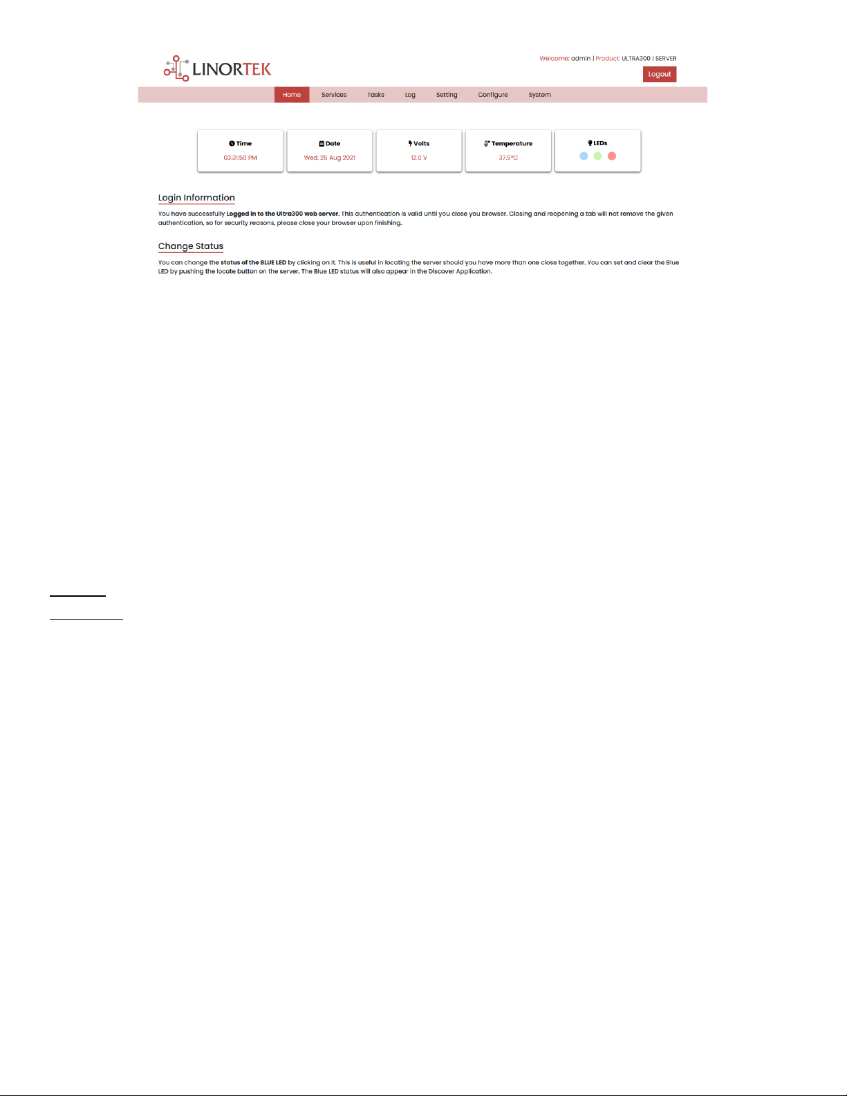
Home
Once your login credentials are entered, you will be redirected to the main page of the application. The Home or Index page displays
some of the system information and offers the ability to locate the physical device if it is in an area with others. See list below for
description.
16
•TIME - Displayed along with the day of the week. This time may be set to be in a 12-hour format with AM/PM indicator or
24-hour format.
•DATE –Current date is displayed here.
•VOLTS –Voltage at the board is displayed. This may be useful if the SERVER is powered along with other equipment, voltage
variance can be noted. The SERVER have an input voltage range of 12-48VDC.
•TEMPERATURE –Temperature on the board is displayed. This display may be either °C or °F. This temperature will be
affected by the heat generated by the SERVER itself so it will always be slightly higher than ambient temperature.
•LEDs - There are 3 LEDs displayed. The RED LED is the system pulse. This should blink about once per second as long as the
server is running. The GREEN LED is used for bootloader options and is generally not visible on the website. The BLUE LED is
clickable and you can turn it on and off from this web page. This is useful for locating the device physically should it be in
use with other similar units as it will illuminate on the unit to which this web browser is connected. The Discoverer program
will also note if the BLUE LED is on. This is often referred to as a "Locate" function.
Services
In/Out Page
The Services tab is dynamic and will change depending on the configuration of your server. This is where you can control the inputs,
outputs, sensors and other specialty controls.
Depending on which SERVER you are using the first page on the SERVICES tab will be either In/Out or Relays., while Relays only has
the relay controls.

17
Select Services –In/Out, the In/Out page is displayed below. The In/Out page has the relay controls and the input controls on one
page. The Ultra 300 SERVER has two relay outputs, two digital inputs and two analog inputs. The relay is named as Relay 1 and Relay
2, digital input is named DIN1 and DIN2, analog input is named AN1 and AN2, you can change the names as desired.
Relay Control
On the In/Out page, the first section is the Relay Control, here you can set the relay property based on your application. Each relay
has a number, in this case 1 to 2.
The State LED show whether the relay is on or off indicated by GREEN and RED respectively. This icon is clickable to manually control
the corresponding relay. Each relay can have a Name as well as identifiers for the Normally Open, Common and Normally Closed
connections.
There are four status LEDs that show:
•Email –If an email is to be sent when this relay is switched on and off
•Pulse –If this Relay is set with a pulse width and pulse width multiplier (duration) –see next section for more information
•Sched. –If there is schedule created in the Tasks page set to automatically trigger this relay.
•Timed –If pulse is set and this relay is activated, the Timed LED will turn red showing the relay is currently operating on a
timer.
Click the Edit Icon to edit the controls for the corresponding relay. This will take you to the Set Relay page.
Set Relay
The SET RELAY page allows you to set various properties pertaining to the Relay.
•Relay Select - The Relay that you are editing is identified by the line on which you clicked the Edit icon on the RELAY page.
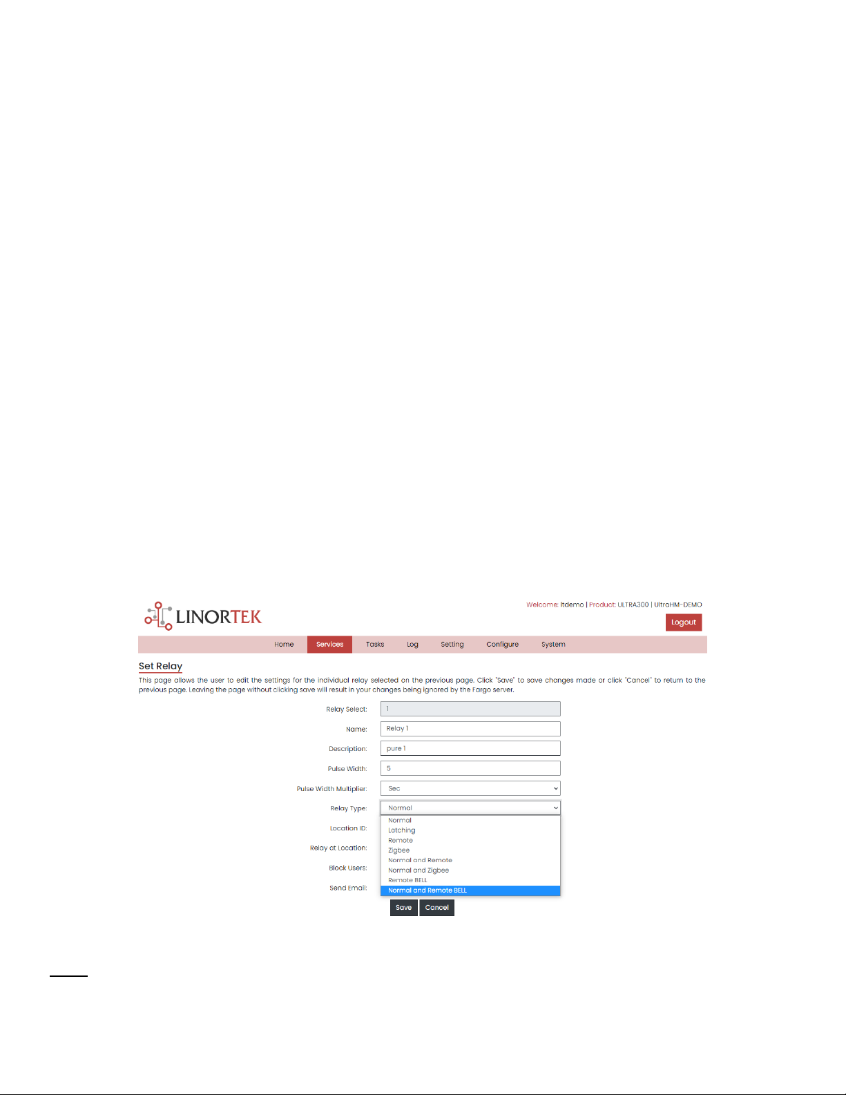
18
•Name - Enter a 15-character Relay Name (Use numbers and letters only, no special characters). This and the following 3
fields may be used for any identify information desired.
•Pulse Width - When you control the relay it turns on or off. You may control it for a timed turned on period by entering a
Pulse Width when 0 means there is no timed event and a number represents duration of the pulse. The maximum number
you can enter here is 4 digits, i.e. 1234.
•Pulse Width Multiplier - To further define the pulse length select a Pulse Width Multiplier to further define the pulse width.
You can select:
•None
•mS (Millisecond, 1/1000 second)
•Sec (Seconds)
•Min (Minutes)
•Relay Type - the SERVER can access relays physically on the SERVER or using other means. You may select:
•Normal - relay physically on the SERVER
•Latched - not currently supported
•Remote - a relay on another Linortek device access over the network
•Zigbee - a relay at a remote device access over an RF system
•Normal and Remote - both relays activated
•Normal and Zigbee - both relays activated
•Remote BELL –to turn on a bell at remote location (for Netbell software only)
•Normal and Remote BELL –to turn on both local and remote bells (for Netbell software only)
•Location ID - this is a number identifying a remote location
•Relay at Location - a number representing the relay or device at the Location
•Send Email - the SERVER can be programmed to send an Email if the relay is turned on or off.
Inputs
The In/Out page will display information from each input, at here you can set the inputs data based on your application.

19
At the top of each input is a label (ex: DIN 1, AIN 2) specifying whether it is a digital input (DIN) or analog input (AIN) as well as the
input number. This label will turn green when the input is enabled. Inside the Box will be any display configured from the Set Input
page (see the pages below for the input setting details). A red dot in the lower-left corner indicating the state of a linked relay (if
any), will turn green when the linked relay is activated. Finally, an Edit icon in the lower-right corner of the box to edit the
corresponding input. This will take you to the Set Digital Input or Set Analog Input page.
Set Digital Input
The Digital Inputs can be set to provide various readouts on using a range of display types. In addition to displaying the input data,
you can name the display as well as associate a relay with it. This relay will change from Green to RED as it goes from on to off as
well as is clickable to control it. By clicking on the edit pencil icon, you can edit the settings for this input:
•Digital Input Selected - The Digital Input that you are editing is identified by the line on which you clicked the Edit icon.
•Name - You can set a 15-character name (use numbers and letters only, no special character) for this input. This name goes
in the bar at the top of the display.
•Label - Set a 7-character label which is displayed on the actual active display.
•Corrector - Using this field you can add, subtract, multiply, or divide a value before the value is shown on the display page.
This is a 2-value corrector with each being separated by a single space character. (ie. "+2, -2, *3, /3")
•USE - Set this input to active. Turns the input number indicator to green. It should be noted that when in use the input
consumes CPU time and other resources depending on its type. Although all inputs may be active at the same time, it is
recommended to turn on only those you want to use.
•Type - The input data can be used to calculate a range of results. You may select:
•State - This is useful for knowing if an input is on or off, like a door switch being on or off.
•CounterNR - This is a non-resettable counter.
•CounterR - This is a resettable counter.
•Frequency - Counts the frequency of an input in KHz (kilo hertz or1/1000 seconds). This could be useful in
displaying a tachometer where 60Hz = 1 R.P.M.
•Period - in 1/1000 seconds an input in kHz (milliseconds or1/1000 seconds). This would be useful for measuring
timed events.
•Display - This selection lets you change the display type used. You can select:
•Dot - A single dot with the value in the middle. This can be used for State. You can make a dumb indicator by
changing the color of the Dot based on the value. The label is under the Dot.
•Values - Displays the Corrected Value with the Label in a box directly below it.
•Meter - This Meter has configurable scale based on the Min/Max values and arcs can be colored per the Color
ranges. The Label is displayed within the Meter.
•VBar - Also based on the Min/Max values for the scale and the bar changes color based on the values in the Color
ranges.
•Relay L/T - Enter a Relay number here. If it is a local relay, it will show Green or RED depending if it is on or off. By clicking
on it the relay will turn on and off. The name comes from the relay settings page. This may be useful if you want to turn the
subject of a display on and off. Any relay can be used on any input and each may be reused for any other input. Adding an L
after the relay number (ex: 2L) will link the state of the input to the state of the relay. This is an easy and immediate way to
have an input follow the relay. Adding a T after the relay number will trigger the relay to the state of the input. This is an
easy and immediate way to have a relay follow the input.
•Command Z/N/I - This field is used for issuing various commands to the Digital Input controller: Z - Zero the resettable
counter. N - Leave the input as Normal. I - Invert the input.

20
•Value - These are Min/Max values used for the display. This is useful for preventing a Meter from going past its end or
setting the value of a VBar. This is the Value after the Corrector. The system cannot display a value past Max so be sure this
is at least set to 1.
•Yellow/Red/Green - There are three colors that can be used to further define a display. Set the range of these colors to
define a color to the display Value. This is the Value after the Corrector. Note that if you are using a State type you may
want to assign RED = From 0 to 0, GREEN = From 1 to 1 and YELLOW = From 2 to 2. Since a State is always either 1 or 0 this
will prevent ambiguous information and prevent the YELLOW color from being used. You can select any two colors you like
for a State type.
Set Analog Input
The Analog Inputs can be set to provide various readouts on using a range of display types. In addition to displaying the input data,
you can name the display as well as associate a relay with it. This relay will change from Green to RED as it goes from on to off as
well as is clickable to control it.
•Analog Input Selected - The Analog Input that you are editing is identified by the line on which you clicked the Edit icon.
•Name - You can set a 15-character name for this input. This name goes in the bar at the top of the display.
•Label - Set a 7-character label which is displayed on the actual active display.
•Corrector - Using this field you can add, subtract, multiply, or divide a value before the value is shown on the display page.
This is a 2-value corrector with each being separated by a single space character. (ie. "+2, -2, *3, /3")
•USE - Sets this input to active. Turns the input number indicator to green. It should be noted that when in use the input
consumes CPU time and other resources depending on its type. Although all inputs may be active at the same time, it is
recommended to turn on only those you want to use.
•Type - The input data can be used to calculate a range of results. You may select:
•Analog 1 - Analog 1 input from a Ultra
•Analog 2 - Analog 2 input from a Ultra
Table of contents
Other Linortek Measuring Instrument manuals

Popular Measuring Instrument manuals by other brands


HYDAC FILTER SYSTEMS
HYDAC FILTER SYSTEMS CMP 43 0-5 Series Installation and maintenance instructions

TESTO
TESTO 310 instruction manual

Measurement Computing
Measurement Computing PCI-DAS6034 user guide

EMH metering
EMH metering LZQJ-XC Series Instructions for use

Xylem
Xylem YSI Alyza IQ NH4 Operation manual

ADWA
ADWA AD100 instructions