LINOVISION IOT-S500 Series User manual
User Guide
Hangzhou Linovision Co., Ltd.
IOT-S500 Series
Applicability
This guide is applicable to IOT-S500 series sensors shown as follows, except where otherwise
indicated.
Model
Description
IOT-S500CO2
Carbon Dioxide Sensor
IOT-S500LGT
Light Sensor
IOT-S500PP
Pipe Pressure Sensor
IOT-S500PT-T200
PT100 Temperature Sensor
IOT-S500SMT
Soil Moisture Sensor
IOT-S500SWL
Submersible Level Sensor
IOT-S500UDL-W050
Ultrasonic Distance/Level Sensor
Safety Precautions
Linovision will not shoulder responsibility for any loss or damage resulting from not following the
instructions of this operating guide.
The device must not be remodeled in any way.
The device is not intended to be used as a reference sensor, and Linovision will not should
responsibility for any damage which may result from inaccurate readings.
Do not place the device close to objects with naked flames.
Do not place the device where the temperature is below/above the operating range.
Make sure electronic components do not drop out of the enclosure while opening.
When installing the battery, please install it accurately, and do not install the reverse or wrong
model.
The device must never be subjected to shocks or impacts.
Declaration of Conformity
IOT-S500 series is in conformity with the essential requirements and other relevant provisions of the
CE, FCC, and RoHS.
All rights reserved.

For assistance,please contact
Linovision technical support:
E-mail:sales@linovision.com
Tel:+86 571-8670 8175
Website:wwww.linovision.com
Revision History
Date
Doc Version
Description
Nov. 23, 2020
V 1.0
Initial version

Content
1. Product Introduction................................................................................................... 5
1.1 Overview.............................................................................................................5
1.2 Features............................................................................................................. 5
2. Hardware Introduction.................................................................................................5
2.1 Hardware Overview.............................................................................................5
2.2 Dimensions(mm)................................................................................................ 6
2.3 Power Button Descriptions................................................................................. 7
3. Basic Configuration..................................................................................................... 8
3.1 Configuration via Smartphone APP.................................................................... 8
4. Advanced Feature Description...................................................................................10
4.1 LoRaWAN Settings........................................................................................... 10
4.2 Basic Settings.................................................................................................. 11
4.3 Calibration........................................................................................................ 11
4.4 Threshold and Alarm........................................................................................ 12
5. Cloud Management................................................................................................... 12
5.1 Add a Linovision Gateway.................................................................................12
5.2 Add IOT-S500 to Cloud..................................................................................... 13
6. Sensor Payload......................................................................................................... 14
6.1 Basic Information............................................................................................. 14
6.2 Sensor Data...................................................................................................... 14
6.3 Downlink Commands........................................................................................16
Appendix....................................................................................................................... 16
Default LoRaWAN Parameters................................................................................16
1. Product Introduction
1.1 Overview
IOT-S500 series is a sensor mainly used for outdoor environment through wireless LoRa network.
IOT-S500 device is battery powered and designed for multiple mounting ways. It is equipped with
NFC (Near Field Communication) and can easily be configured by a smartphone or a PC software.
Sensor data are transmitted in real-time using standard LoRaWAN®protocol. LoRaWAN®enables
encrypted radio transmissions over long distance while consuming very little power.
The user can obtain sensor data and view the trend of data change through Cloud or through the
user’s own Network Server.
1.2 Features
Up to 11km communication range
Easy configuration via NFC
Standard LoRaWAN®support
Low power consumption with 19000mAh replaceable battery
2. Hardware Introduction
IOT-S500 series sensors is made up of a LoRa transceiver and a sensor. Among them, ultrasonic
sensors and gas sensors are combined with LoRa transceiver.
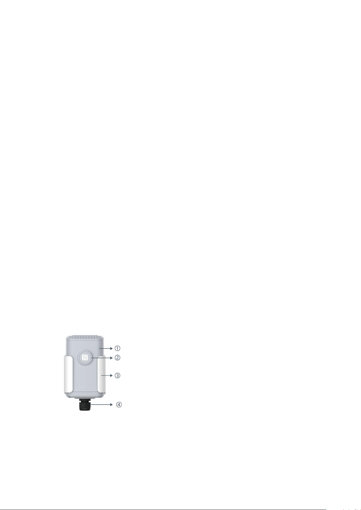
2.1 Hardware Overview
Front View of IOT-S500:
①LoRa Antenna (Internal)
②NFC Area
③Water-proof Connector
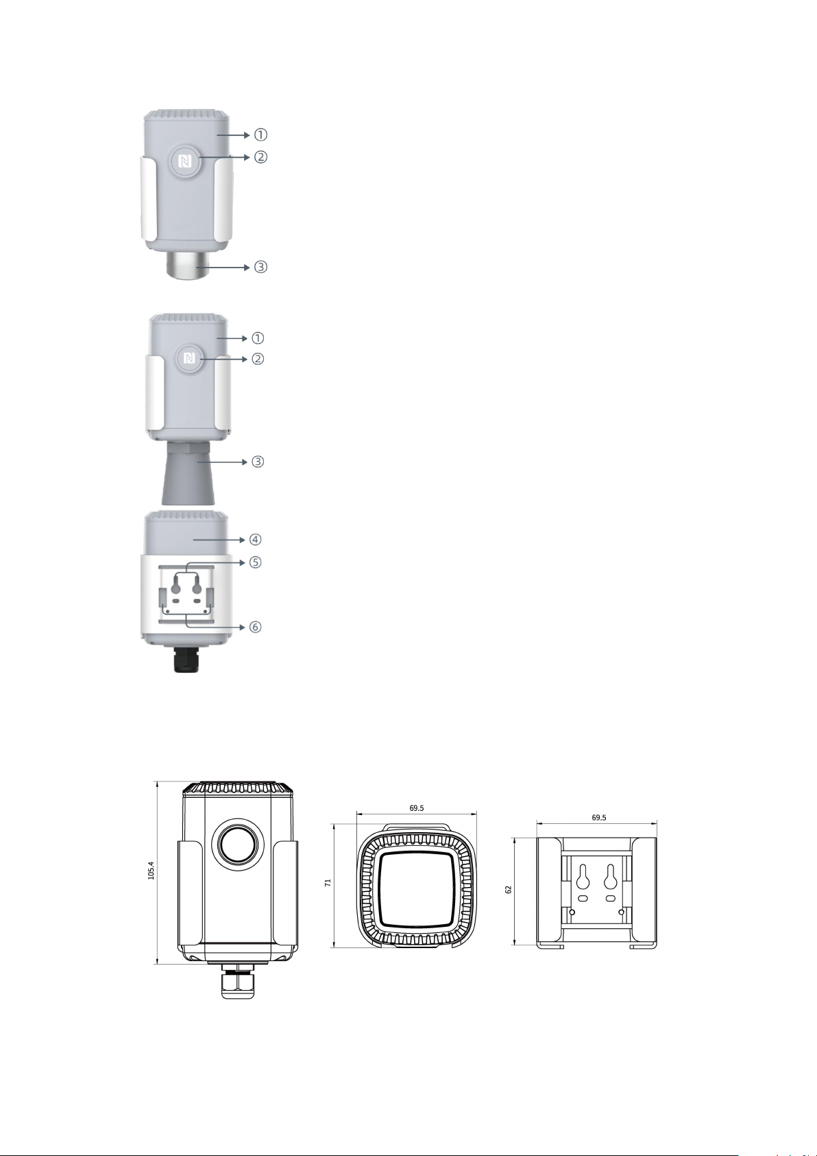
2.2 Dimensions(mm)
IOT-S500
Back View:
④Battery (Internal)
⑤Wall Mounting Holes
⑥Pole Mounting Holes
Front View of IOT-S500CO2
①LoRa Antenna (Internal)
②NFC Area
③Vent Tube
Front View of IOT-S500UDL-W050
①LoRa Antenna (Internal)
②NFC Area
③Ultrasonic Horn
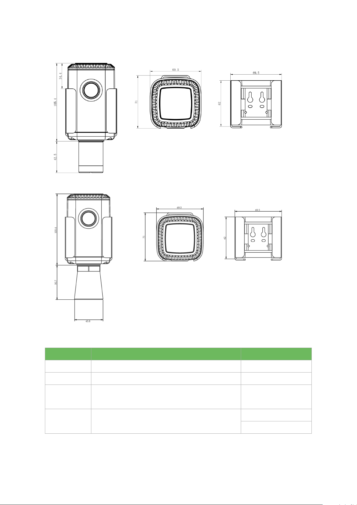
IOT-S500CO2
IOT-S500UDL-W050
2.3 Power Button Descriptions
Note: IOT-S500 can also be turned on/off and reset via Mobile APP or Toolbox.
Function
Action
LED Indication
Turn On
Press and hold the button for more than 3s.
Off →Static Green
Turn Off
Press and hold the button for more than 3s.
Static Green -> Off
Reset
Press and hold the button for more than 10s.
Note: IOT-S500 will automatically power on after reset.
Blink 3 times.
Check
On/Off Status
Quickly press the power button.
Light On: Device is on.
Light Off: Device is off.
3. Basic Configuration
In order to protect the security of sensor, password validation is required when configuring via
unused phone . Default password is 123456.
3.1 Configuration via Smartphone APP
Preparation:
Smartphone (NFC supported)
Toolbox APP: download and install from Google Play or Apple Store.
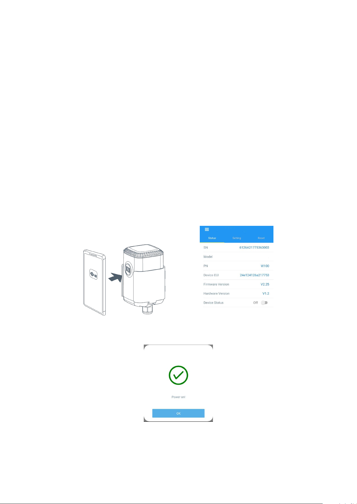
3.1.1 Read/Write Configuration via NFC
1. Enable NFC on the smartphone and open“Toolbox”APP.
2. Attach the smartphone with NFC area to the device to read basic information.
Note: Ensure the location of smartphone NFC area and it is recommended to take off phone case
before using NFC.
3. Change the on/off status or parameters, then attach the smartphone with NFC area to the device
until the APP shows a successful prompt.
4. Go to“Device > Status” to tap“Read”and attach the smartphone with NFC area to the device to
read real-time data of sensor.
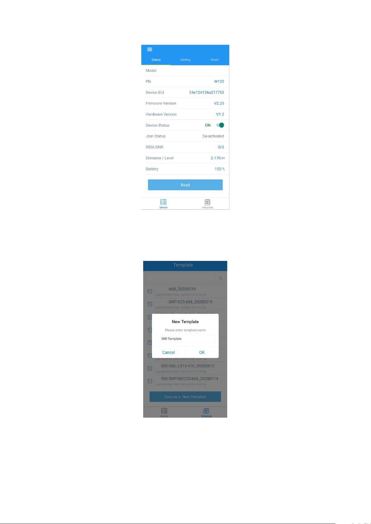
3.1.2 Template Configuration
Template settings only work for easy and quick device configuration in bulk.
Note: Template function is allowed only for sensors with the same model and LoRa frequency band.
1. Go to “Template” page on the APP and save current settings as a template.
2. Attach the smartphone with NFC area to another device.
3. Select the template file from Toolbox APP and tap “Write”,keep the two devices close until the
APP shows a successful prompt.

4. Slide the template item to the left to edit or delete the template.
4. Advanced Feature Description
4.1 LoRaWAN Settings
Parameters
Description
Default
Device EUI
Unique ID of the sensor. It can be found on the label.
On the label
App EUI
App EUI of the sensor.
24E124C0002A0001
Application Port
The port used for sending or receiving data. Default:
85
Join Type
OTAA or ABP mode.
Note: If you use cloud to manage sensors, please
select OTAA mode.
OTAA
Application Key
Appkey of the sensor.
5572404C696E6B4C6F
52613230313823
Network ID
NetID of the sensor used for identifying LoRaWAN
networks.
0x010203
Device Address
DevAddr of the sensor.
The 5th to 12th digits of
SN.
Network Session
Key
Nwkskey of the sensor.
5572404C696E6B4C6F
52613230313823
Application
Appskey of the sensor.
5572404C696E6B4C6F
Session Key
52613230313823
Spread Factor
Select spread factor from SF7 to SF12.
SF10-DR2
Confirmed Mode
If the sensor does not receive ACK package from
network server, it will resend data 3 times most.
Disabled
Rejoin Mode
Sensor will send specific mounts of LoRaMAC
packages to check connection status regularly. If no
reply after specific packages, the sensor will re-join.
Enabled, 8 packages
ADR Mode
Allow network server to adjust datarate of the
sensor.
Enabled
Support
Frequency
LoRaWAN region.
EU868
AU915
Channel
Enable or disable LoRa channels.
If frequency is one of CN470/AU915/US915, you can
enter the index of the channel that you want to
enable in the input box, making them separated by
commas.
Examples:
1, 40: Enabling Channel 1 and Channel 40
1-40: Enabling Channel 1 to Channel 40
1-40, 60: Enabling Channel 1 to Channel 40 and
Channel 60
All: Enabling all channels
Null: Indicates that all channels are disabled
Appendix
4.2 Basic Settings
Parameters
Description
Reporting Interval
Interval of sending sensor data. Default: 10min.
Change Password
Change the password of logging Toolbox (Windows) and parameter
modify(mobile APP).
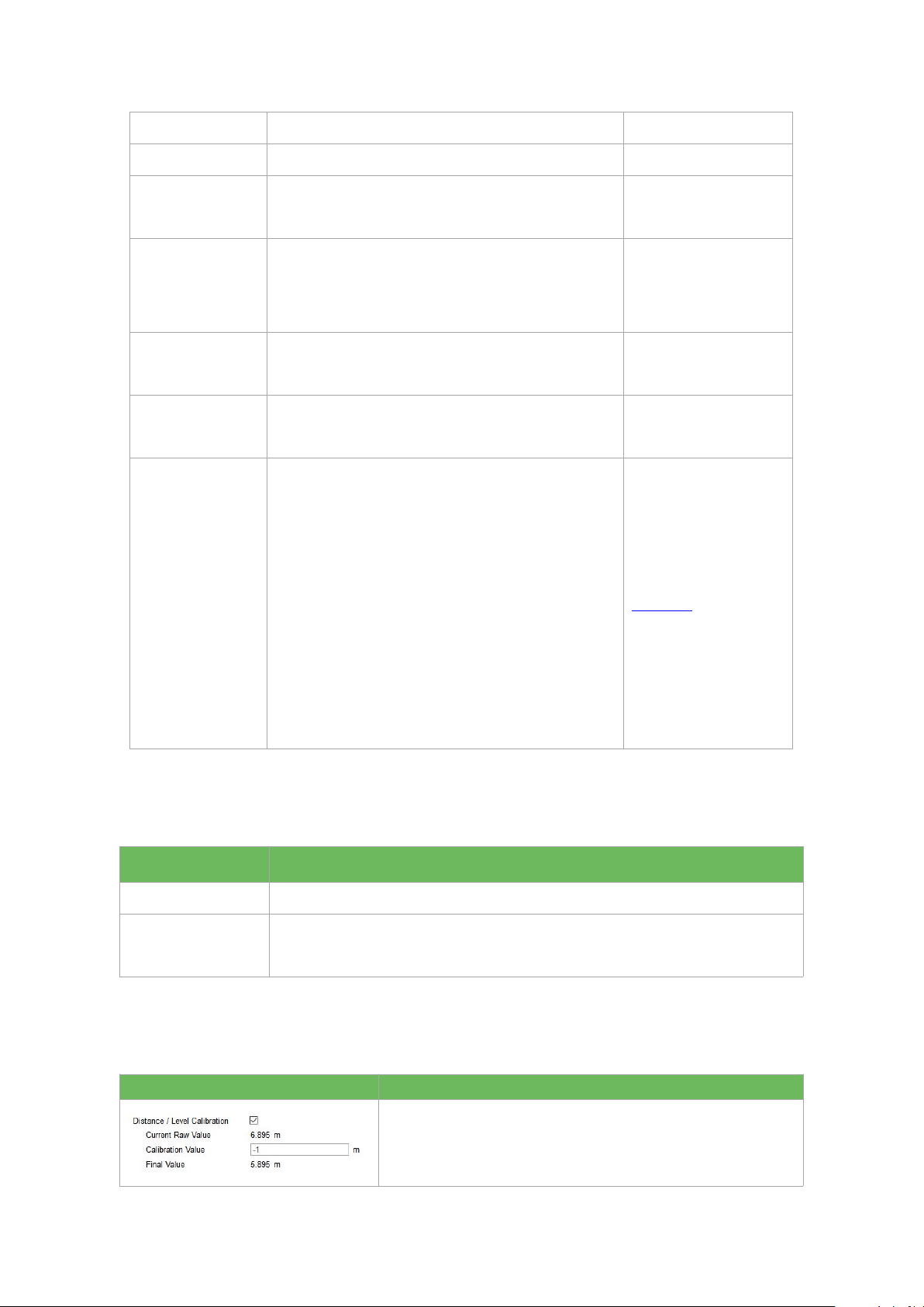
4.3 Calibration
Parameters
Description
After saving the calibration value, the sensor will add the
calibration value to raw value and send the final value.

If current value exceeds the outlier range/values, the sensor
will re-collect the value.
Note: This item is only for IOT-S500UDL-W050.
4.4 Threshold and Alarm
Parameters
Description
Over/Below
Maximum/minimum data to trigger the alarm. After triggered, sensor will
send current data ignoring report interval.
Data Collecting Interval
The sensor will detect and check whether the value is triggered again after
data collecting interval.
5. Cloud Management
5.1 Add a Linovision Gateway
1. Enable “Linovision” type network server and “Cloud” mode in gateway web GUI.
Note: Ensure gateway has accessed the Internet.

2. Go to “My Devices” page and click “+New Devices” to add gateway to Cloud via SN. Gateway will
be added under “Gateways” menu.
3.Check if gateway is online in Cloud.
5.2 Add IOT-S500 to Cloud
1. Go to “My Devices” page and click “+New Devices”. Fill in the SN of IOT-S500 and select
associated gateway.
2. After IOT-S500 is connected to Cloud, you could check the device information and data and create
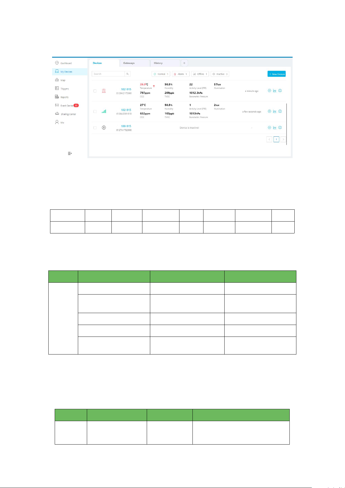
dashboard for it.
6. Sensor Payload
All data are based on following format(HEX):
Channel1
Type1
Data1
Channel2
Type2
Data2
Channel 3
...
1 Byte
1 Byte
N Bytes
1 Byte
1 Byte
M Bytes
1 Byte
...
6.1 Basic Information
IOT-S500 sensors report basic information of sensor everytime joining the network.
6.2 Sensor Data
IOT-S500 sensors report sensor data according to reporting interval (10min by default). Battery level
is reported every 24 hours.
IOT-S500CO2
Channel
Type
Data Example
Description
ff
01(Protocol Version)
01
V1
09 (Hardware Version)
01 40
V1.4
0a(Software Version)
01 14
V1.14
0f(Device Type)
00
Class A
16(Device SN)
64 10 90 82 43 75 00 01
Device SN is
6410908243750001
Channel
Type
Data Example
Description
01
75(Battery Level)
64
64=>100
Battery level =100%
IOT-S500LGT
IOT-S500PP
IOT-S500PT-T200
IOT-S500SMT
03
67 (Temperature)
10 01
10 01 => 01 10 = 272
Temp=272*0.1=27.2°C
04
68(Humidity)
71
71=>113
Hum=113*0.5=56.5%
05
7d(CO2)
67 04
67 04 => 04 67 =1127 ppm
06
73(Barometric
Pressure)
68 27
68 27=>27 68=10088
Pressure=10088*0.1=1008.8hPa
Channel
Type
Data Example
Description
01
75(Battery Level)
64
64=>100
Battery level =100%
03
94 (Light)
50 00 00 00
50 00 00 00=>00 00 00 50=80 lux
Channel
Type
Data Example
Description
01
75(Battery Level)
64
64=>100
Battery level =100%
03
7b (Pressure)
0a 00
0a 00=>00 0a=10kPa
Channel
Type
Data Example
Description
01
75(Battery Level)
64
64=>100
Battery level =100%
03
67 (Temperature)
10 01
10 01 => 01 10 = 272
Temp=272*0.1=27.2°C
Channel
Type
Data Example
Description
01
75(Battery Level)
64
64=>100
Battery level =100%

IOT-S500SWL
IOT-S500UDL-W050
6.3 Downlink Commands
IOT-S500 sensors support downlink commands to configure the device. Application port is 85 by
default.
Appendix
Default LoRaWAN Parameters
DevEUI
24E124 + 2nd to 11th digits of SN
e.g. SN = 61 26 A1 01 84 96 00 41
Then Device EUI = 24E124126A101849
AppEUI
24E124C0002A0001
03
67 (Temperature)
10 01
10 01 => 01 10 = 272
Temp=272*0.1=27.2°C
04
68(Moisture)
71
71=>113
Hum=113*0.5=56.5%
05
7d(Conductivity)
f0 00
f0 00 => 00 f0 =240 µs/cm
Channel
Type
Data Example
Description
01
75(Battery Level)
64
64=>100
Battery level =100%
03
77 (Water Level)
02 00
02 00=>00 02=2cm
Channel
Type
Data Example
Description
01
75(Battery Level)
64
64=>100
Battery level =100%
03
82 (Distance)
1e 00
1e 00=>00 1e=30mm
Channel
Type
Data Example
Description
ff
03(Set Reporting Interval)
b0 04
b0 04 => 04 b0 = 1200s

Appport
0x55
NetID
0x010203
DevAddr
The 5th to 12th digits of SN
e.g. SN = 61 26 A1 01 84 96 00 41
Then DevAddr = A1018496
AppKey
5572404C696E6B4C6F52613230313823
NwkSKey
5572404C696E6B4C6F52613230313823
AppSKey
5572404C696E6B4C6F52613230313823
-END-
This manual suits for next models
7
Table of contents
Other LINOVISION Accessories manuals


Popular Accessories manuals by other brands


ESI
ESI FlexCharge3 FCH3-DSK-BLK Assembly and operation instructions

Louroe Electronics
Louroe Electronics AP-8TB Installation and operating instructions

NuTone
NuTone 101T installation instructions

Hyundai
Hyundai WSC instruction manual

Axon
Axon Body 2 quick start guide

HikRobot
HikRobot SC2000E Mini Series quick start guide

Point Six
Point Six WOWPIR Installation and operation instructions

DSC
DSC WLS914 Installation instructions manual

Zoom
Zoom U-44 Operation manual

Aeroball
Aeroball Sr.2 product manual

Scame electrical solutions
Scame electrical solutions ADVANCE-GRP 24V Series Installation, use and maintenance

Spralla
Spralla 3D pen user manual