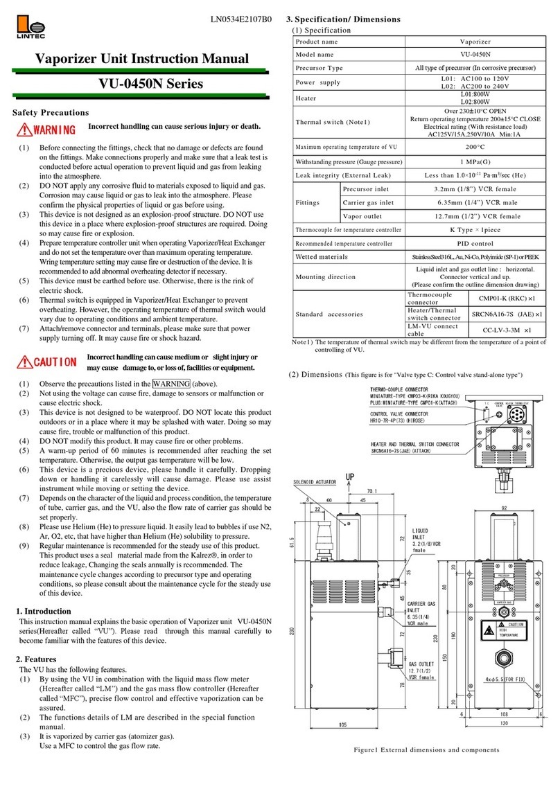
Lintec VU-0430N Series User manual

LN0405E2107B0
Vaporizer Unit Instruction Manual
VU-0430N Series
Safety Precautions
Incorrect handling can cause serious injury or death.
(1) Before connecting the fittings, check that no damage or defects are found
on the fittings. Make connections properly and make sure that a leak test is
conducted before actual operation to prevent liquid and gas from leaking
into the atmosphere.
(2) DO NOT apply any corrosive fluid to materials exposed to liquid and gas.
Corrosion may cause liquid or gas to leak into the atmosphere. Please
confirm the physical properties of liquid or gas before using.
(3) This device is not designed as an explosion-proof structure. DO NOT use
this device in a place where explosion-proof structures are required. Doing
so may cause fire or explosion.
(4) Prepare temperature controller unit when operating Vaporizer/Heat Exchanger
and do not set the temperature over than maximum operating temperature.
Wring temperature setting may cause fire or destruction of the device. It is
recommended to add abnormal overheating detectorifnecessary.
(5) This device must be earthed before use. Otherwise, there is the rink of
electric shock.
(6) Thermal switch is equipped in Vaporizer/Heat Exchanger to prevent
overheating. However, the operating temperature of thermal switch would
vary due to operating conditions and ambient temperature.
(7) Attach/remove connector and terminals, please make sure that power
supply turning off. It may cause fire or shock hazard.
Incorrecthandlingcancausemediumor slightinjuryor
maycause damageto,orlossof,facilitiesorequipment.
(1) Observe the precautions listed in the WARNING (above).
(2) Not using the voltage can cause fire, damage to sensors or malfunction or
cause electric shock.
(3) This device is not designed to be waterproof. DO NOT locate this product
outdoors or in a place where it may be splashed with water. Doing so may
cause fire, trouble or malfunction of this product.
(4) DO NOT modify this product. It may cause fire or other problems.
(5) A warm-up period of 60 minutes is recommended after reaching the set
temperature. Otherwise, the output gas temperature will be low.
(6) This device is a precious device, please handle it carefully. Dropping
down or handling it carelessly will cause damage. Please use assist
instrument while moving or setting the device.
(7) Depends on the character of the liquid and process condition, the
temperature of tube, carrier gas, and the VU, also the flow rate of carrier
gas should be set properly.
(8) Please use Helium (He) to pressure liquid. It easily lead to bubbles if use
N2, Ar, O2, etc, that have higher than Helium (He) solubility to pressure.
(9) Regular maintenance is recommended for the steady use of this product.
This product uses a seal material made from the Kalrez®, in order to
reduce leakage, Changing the seals annually is recommended. The
maintenance cycle changes according to precursor type and operating
conditions, so please consult about the maintenance cycle for the steady use
of this device.
1. Introduction
This instruction manual explains the basic operation of Vaporizer unit
VU-0430N Series (Hereafter called “VU”). Please read through this manual
carefully to become familiar with the features of this device.
2. Features
The VU has the following features.
(1) By using the VU in combination with the liquid mass flow meter
(Hereafter called “LM”) and the gas mass flow controller (Hereafter
called “MFC”), precise flow control and effective vaporization can be
assured.
(2) Maximum operating temperature of 200℃.
(3) Compact size
3. Specification/ Dimensions
(1) Specification
Product name
Vaporizer
Model name
VU-0430N
Ratedpower
supply voltage
andheater
capacity
Vaporizer model: D01
Inner AC 120V 80W
Outer AC 120V 100W
Vaporizer model: D02
Inner AC 240V 225W
Outer AC 240V 400W
Thermal switch (Note1)
230±10°C OPEN
Thermal switch connection method
Outer block: 1piece, Inner block: 1piece
Direct connection (125V/15A, 250V/10A)
Operating primary pressure
150 to 300 kPa(G)
Operating secondary pressure
Less than 25 kPa(G)
Pressure Limit (Gauge pressure)
1MPa(G)
Leak integrity (External Leak)
Less than 5.0×10⁻¹⁰ Pa∙m3/sec (He)
Fittings
Precursor inlet
3.2mm (1/8”) VCR Male
Carrier gas inlet
6.35mm (1/4”) VCR Male
Gas outlet
6.35mm (1/4”) VCR Female
Thermocouple for temperature controller
K Type × 2pieces
Recommended temperature controller
PID control type
Wetted materials
StainlessSteel316L, Au, Ni-Co,
Polyimide or PEEK
Mounting direction
Piping line: horizontal.
Power supply connector: vertical and up.
(Please confirm the outline dimension drawing)
Standard
accessories
Thermocouple
connector
CMP01-K(RKC) × 2pieces
Heater/Thermal switch
connector
SRCN6A16-7S (JAE) × 1piece
LM-VU connect
cable
CC-LV-3-3M× 1piece
Note1) The temperature of thermal switch may be different from the temperature of a point of
controlling of VU.
(2) Dimensions
Fig1. External dimensions and components

4. Ordering Information
VU –0430N -A CL -02 P NND01 T23 NNN
[1] [2] [3] [4] [5] [6] [7] [8] [9] [10]
[1] Series model: VU: Vaporizer VU Series
[2] Valve type
A: Control valve and Shut-off valve all-in-one
F: Shut-off valve all-in-one
[3] Carrier gas
CL: Carrier gas-less type 01: Carrier gas type 1
02: Carrier gas type 2 03: Carrier gas type 3
[4] Capillary
02: Capillary type 2 03: Capillary type 3
[5] Valve
P: Polyimide E: PEEK
[6] Seal
N: Au
[7] Internal surface treatment
N: No treatment M: Electrical polishing(EP)
[8] Heater
D01: AC100 to 120V D02: AC200 to 240V
[9] Thermal switch
T23: 230±10°C
[10] Option
NNN: Standard specifications
※Notation other than NNN means customer options. The specification will be different
from this specification sheet, please refer to specific specification sheet. Please notice
that the pin assignment may be different as well.
5. Electrical Connection
(1) Heater / Thermal switch connector
Mounted connector : SRCN2A16-7P (JAE)
Pair connector : SRCN6A16-7S (JAE)
Pin No.
Signal name
1,2
Inner block heater power supply
3,4
Outer block heater power supply
5
Case Gnd.
6,7
Thermal switch
(2) Thermocouple connector
Mounted connector : CMP03-K (RKC Instrument Inc.)
Pair connector : CMP01-K (RKC Instrument Inc.)
Pin No.
Signal name
K
Thermocouple (-)
+
Thermocouple (+)
(3) LM-VU connect cable
Mounted connector : HR10-7R-4P (73)
Pair connector : HR10-7P-4S (73)
Pin No.
Signal name
1
Valve control signal
2
Valve control signal (-15VDC)
3,4
N.C.
6. Connection diagram
Fig2. Connection diagram (Heater specifications: D01: 120V)
Fig3. Connection diagram (Heater specifications: D02: 240V)
7. Preparation and Operational Procedure
(1) Checktheliquidtype, and attachthe VUfittingsinthedirectionofthe fluid flow.
(2) Prepare a MFC for carrier gas (including power indicator and cable) and
connect it to the carrier gas lines.
(3) Attach filters to liquids and carrier gases lines.
(4) Prepare temperature control units and connect to the VU and outlet tubing
heaters.
(5) Electrical connections should be made correctly, taking account of power
source voltage, polarity and capacity.
(6) Supply power to the LM and the MFC, and warm-up for 30 minutes. Please
turn on the VU heaters and confirm that the temperature has reached the set
temperature after a period of 90 minutes.
(7)Check that there are no leaks from the fittings using a helium (He) leak detector.
(8) Evacuate and purge the tubing line, the LC and the VU to remove
moisture, thoroughly.
(9) Thermal switch may work by temperature overshoot in the first operation.
Please adjust PID by auto turning.
(10) When using a liquid mass flow meter and carrier gas mass flow controller
together with this device to control and introduce liquid, vaporized gas will be
transported from the outlet.
(11) Please use helium (He) to pressure liquid (To lower the possibility of
generating bubbles).
(12) It is necessary to set the VU, line and carrier gas temperature as well as
carrier gas flow rates to appropriate values in order to meet the liquid physical
properties and process conditions.
8. Product Warranty
(1) Period
This product is guaranteed for a period of 1 year from the date of
shipment. Defects are repaired according to the following regulations.
(2) Scope
Warranty coverage is restricted to this product only. Any other
damage caused by this product is not covered.
(3) Disclaimer facts
The following repairs are not covered by the warranty.
1) Failure caused by by-product of liquid or gas used.
2) Failure caused by misuse (including careless operation), incorrect
repair or modification.
3) Failure cause by falling or dropping after purchase.
4) Failure caused by fire, earthquake, flood, lightning or other
natural disasters.
Even if the warranty period is still in effect, repair service may not
be provided in the following cases.
1) When the kind of fluid used in the product is unclear.
2) The product is returned with fluid remaining inside, and
safety cannot be confirmed.
This instruction manual is subject to revision without notice.
http://www.lintec-mfc.co.jp
CorporateHeadquarters
4-1-23Sekinotsu,OtsuCity, ShigaPref.520-2277,Japan
TEL. +81-(0)77-536-2210FAX.+81-(0)77-536-2215
TokyoBranchOffice
3FHattoriBuild.,4-30-14YotsuyaShinjyuku-kuTokyo160-0004,Japan
TEL. +81-(0)3-5366-2801FAX.+81-(0)3-3341-3513
Other Lintec Vaporizer manuals
