Linus Roadster Classic User manual

Roadster Classic | Avanti 1 | Dutchi 1 | Scout 1
ASSEMBLY GUIDE
1-SPEED
COASTER &
FREEWHEEL
Illustrations are based off of Roadster Classic but instructions apply to all of these models:
Please review Assembly Guide in its entirety before beginning bicycle assembly. If you do not feel fully
capable of assembly or do not have the proper tools please contact your local bicycle shop to assemble.
2
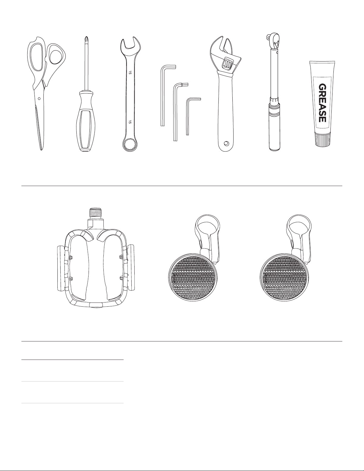
Required Tools (not included)
Parts (included)
Unpacking
Open top of the bicycle box. Remove
bicycle, saddle and parts box.
We recommend using the flat box as a
work surface for bicycle assembly.
Remove protective packaging carefully.
Do not bend spokes when removing the
front wheel.
SCISSORS PHILIPS HEAD
SCREWDRIVER
15MM WRENCH ALLEN WRENCH
6MM, 5MM, 4MM
ADJUSTABLE
WRENCH
PEDALS
x2
FRONT REFLECTOR
x1
REAR REFLECTOR
x1
(ONLY INCLUDED WITH
MODELS W/OUT FENDERS)
LUBRICATING
GREASE*
* Available at auto parts, hardware, or bicycle stores.
** Failure to tighten bolts to the required torque specications can lead to
component failure ultimately leading to serious injury or death.
TORQUE
WRENCH**
C
A
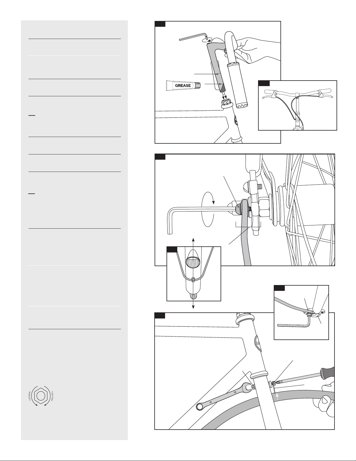
1. Stem Installation
1.1 Apply a small amount of grease around
the bottom 1.5” (35mm) of the stem (A).
Insert stem into the steerer tube so
that the minimum insertion line (B)
is not visible.
1.2 Check cable routing. Make sure that
no cable is pinched or obstructed.
Tighten with the 6mm Allen wrench (C).
Torque Requirement: 20-23Nm.
2. Rear Fender Brace Installation
2.1 Unthread the rear-most bolts from the
rear dropouts using a 4mm hex wrench (A).
2.2 Center fender brace at back of
fender (B).
2.1 Thread 4mm bolts through the brace
eyelets and screw them back into the
dropouts (C). Torque Requirement: 4-5Nm.
3. Front Fender Installation
3.1 Unscrew the bolt at the front of the fork
crown (B) with a philips head screwdriver
while holding the nut on the back side of
the fork crown (A) with a 10mm wrench.
Do not misplace the crescent washer.
Insert bolt through the fender mounting
flange (C) and the crescent washer
with curved side facing the fork crown.
Place flat washer over the end of the bolt
followed by threading on the nut (A) then
tighten lightly.
Push the fender upward until it stops and
then completely tighten the nut.
Torque Requirement: 6.5-9Nm
3.2 Unthread bolts from the fork
drop outs (D) using a 4mm hex wrench.
Center fender brace. Thread bolts
through the brace eyelets (E) and
screw them back into the dropouts.
Torque Requirement: 4-5Nm.
A
B
C
C
3.1
2.1
1.1
(applicable to Dutchi 1; see page 4
for Scout 1 front fender installation)
(Applicable to Dutchi 1 & Scout 1)
E
3.2
B
A
C
2.2 B
D
1.2
3
A
C
D
C
4.1
4.2
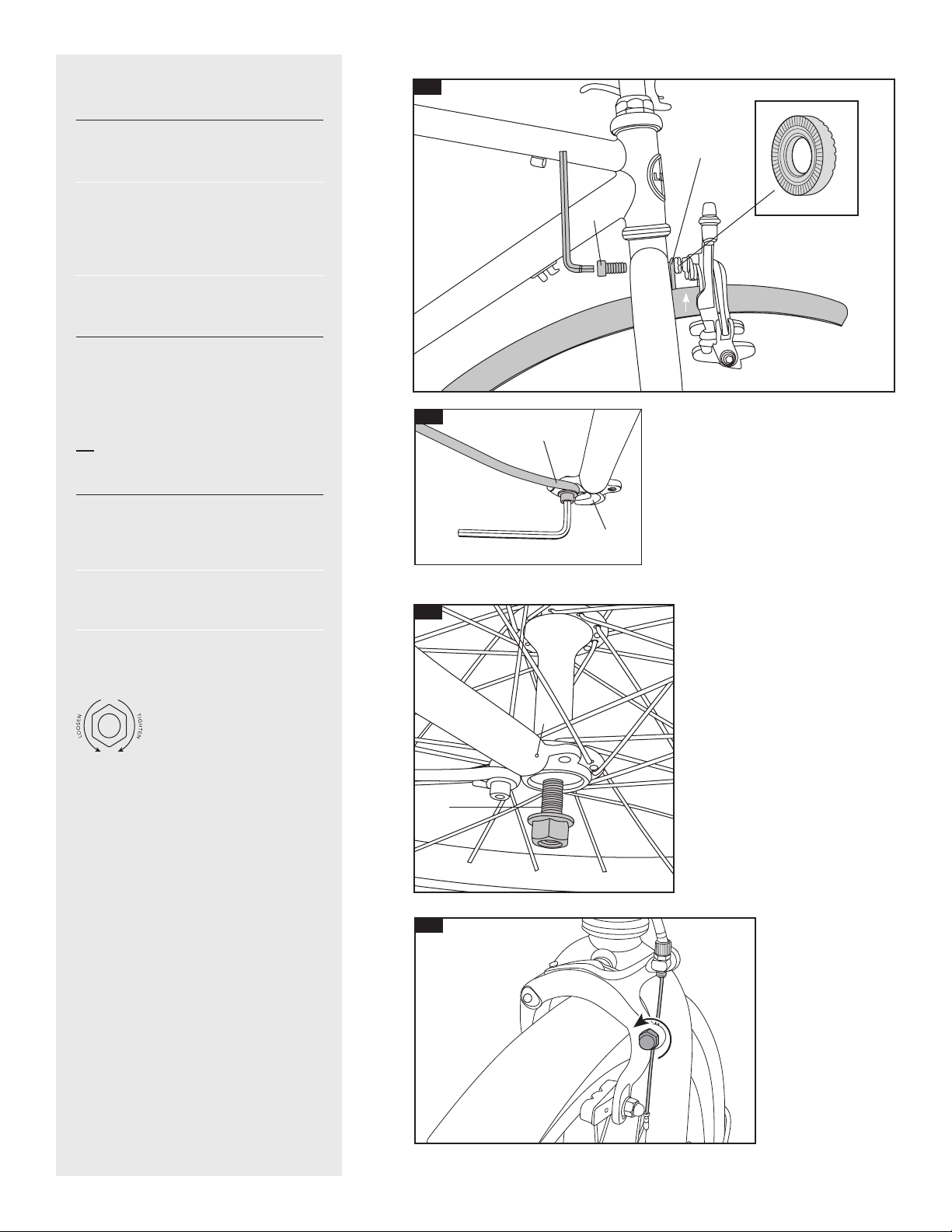
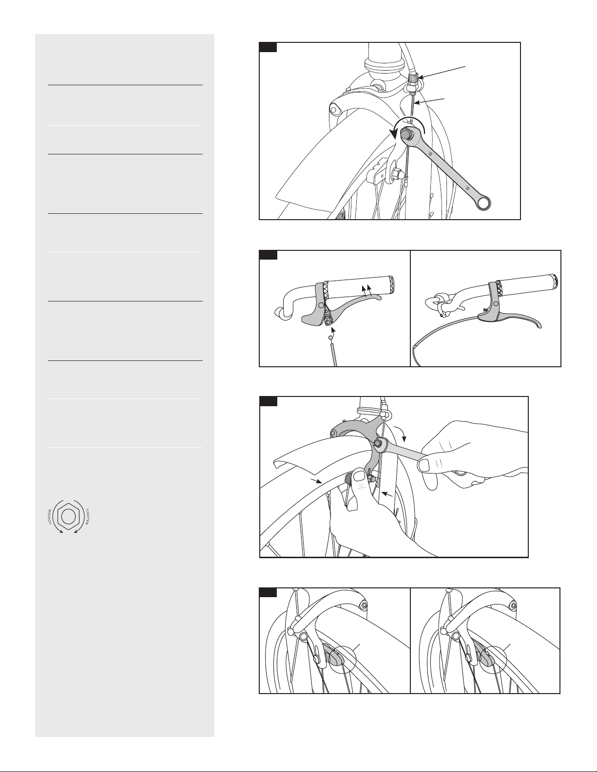
4. Front Fender Installation
11.1 Unscrew the brake nut from the back
of the fork (A) using a 5mm hex wrench.
Do not misplace the knurled washer (B).
Keep the knurled washer next to the brake
caliper and slide the brake bolt through
the fender mounting flange (C). Insert the
brake bolt back into the fork and tighten
the brake nut lightly.
Push the fender upward until it stops and
then completely tighten the brake bolt.
Torque Requirement: 6.5-9Nm
11.2 Unthread bolts from the fork
drop outs (C) using a 4mm hex wrench.
Center fender brace. Thread bolts
through the brace eyelets (D) and
screw them back into the dropouts.
Torque Requirement: 4-5Nm.
(For Scout 1 with Caliper Rim Brake)
4
A
B
5.1
5.2
5. Front Wheel Installation
5.1 Use 15mm wrench to loosen the nuts
on the front wheel enough to slide the axle
(A) into the fork dropouts (B). Make sure to
seat the axle completely in the dropouts.
5.2 If the wheel cannot slip past the
brakes, loosen the cable tension using
10mm wrench.
5.1 Tighten the axle nuts. Torque
Requirement: 30-45Nm.
B
6.1
0°
C
6.3
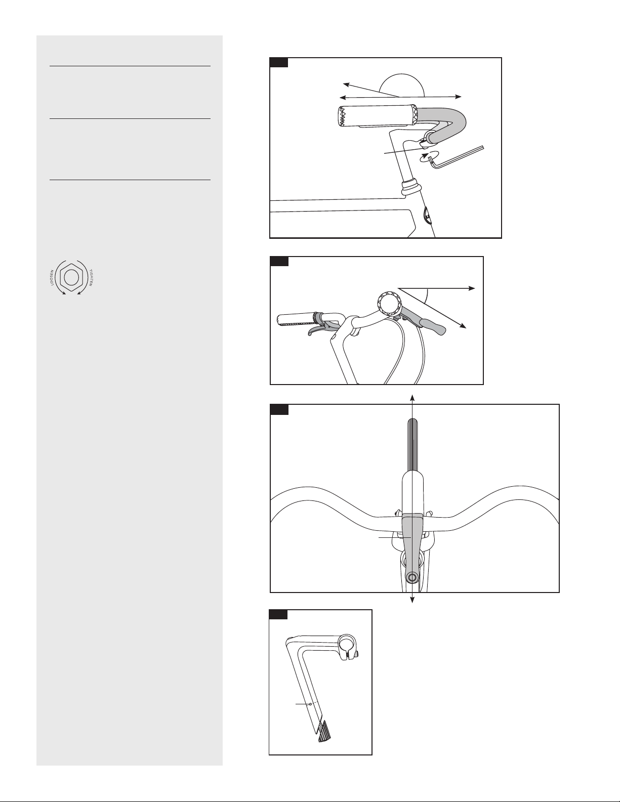
6. Stem/Handlebar Adjustment
6.1 Using a 6mm hex wrench, loosen the
bolt in the front of the stem (A) and adjust
the handlebars so that they are level then
re-tighten. Torque Requirement: 10-12Nm.
6.2 Using a 5mm hex wrench, loosen the
bolt on the bottom of the brake lever.
Adjust the angle levers so that they point
downward (20-45°) and then
re-tighten. Torque Requirement: 6-8Nm.
6.3 Check to make sure the stem is in line
with the front wheel and that the
minimum insertion line (B) is not visible.
Use the 6mm hex wrench to loosen the
stem, adjust and then tighten (C). Torque
Requirement: 20-23Nm.
A
B
6.3
20-45°
6.2
5
7.1
7. Front Brake Adjustment
(does not apply to U.S. Roadster
Classic, Dutchi 1 or Avanti)
7.1 Using 10mm wrench loosen the
cable clamp bolt (A) enough for the cable
(B) to move freely.
Turn the cable adjustment bolt (C)
anti-clockwise 2 full turns.
7.2 Pull back the left-hand brake lever
and insert cable end into the brake lever.
Then pull cable back through the brake
caliper body and slide the cable housing
so that it meets the brake lever.
7.3 With one hand squeeze the brake cal-
iper closed so that the brake pads are in
contact with both sides of the rim.
With your other hand, pull the brake
cable taut to remove any slack then
tighten the cable clamp bolt. Torque
Requirement: 6-8Nm.
7.4 Check to see that the brake pads are
parallel and centered on the brake track.
If they are not, loosen the pads with a
10mm wrench, center them and
tighten. Torque Requirement: 4-5Nm.
Squeeze the brake lever hard about 10
times to seat the cables, housing, and to
stretch the cable.
Once the cable has seated loosen the
cable clamp bolt, squeeze the brake
caliper together, remove cable slack and
re-tighten. Torque Requirement: 6-8Nm.
Finally, rotate the cable adjustment
bolt clockwise 1-2 turns to fine-tune
how quickly the brakes grab.
7.4
7.2
CORRECT INCORRECT
B
7.3
C
A
6

8.1
8. Rear Brake Adjustment
(applicable to Scout 1 model)
8.1 Using 10mm wrench loosen the
cable clamp bolt (A) enough for the cable
(B) to move freely.
Turn the cable adjustment bolt (C)
anti-clockwise 2 full turns.
8.2 With one hand squeeze the brake
caliper closed so that the brake pads are
in contact with both sides of the rim.
With your other hand, pull the brake
cable taut to remove any slack then
tighten the cable clamp bolt. Torque
Requirement: 6-8Nm.
8.3 Check to see that the brake pads are
parallel and centered on the brake track.
If they are not, loosen the pads with a
10mm wrench, center them and
tighten. Torque Requirement: 4-5Nm.
Squeeze the brake lever hard about 10
times to seat the cables, housing, and to
stretch the cable.
Once the cable has seated loosen the
cable clamp bolt, squeeze the brake
caliper together, remove cable slack and
re-tighten. Torque Requirement: 6-8Nm.
Finally, rotate the cable adjustment
bolt clockwise 1-2 turns to fine-tune
how quickly the brakes grab.
8.3
B
8.2
C
A
7
INCORRECT CORRECT

9. Pedal Installation; READ FIRST!
(POTENTIAL FOR DAMAGE IF
INSTALLED INCORRECTLY!)
9.1 Pedals are side-specific. Check the
ends of the axles (A) to identify which
side of the bicycle to install them in.
R = Side of bicycle with chain.
Apply a small amount of grease to the
pedal threads.
9.2 Install the pedal marked R by turning
the axle CLOCKWISE.
Install the pedal marked L turning the
axle ANTI-CLOCKWISE.
Tighten the pedal axles fully with the
15mm wrench. Torque Requirement:
28-37Nm.
10. Seat Post Installation
10.1 Apply a small amount of grease
around the bottom 1.5” (35mm) of the seat
post (A) and insert the seat post into the
seat tube so that the minimum insertion
line (B) is not visible.
10.2 Align the saddle with the bicycle’s top
tube as shown.
10.1 Tighten down the seat post clamp (C)
using the appropriate hex wrench.
Torque Requirement: 4.5-6Nm.
10.1 Check to make sure that the saddle is
level (D). If it is not, use a 6mm wrench to
loosen the saddle clamp, adjust the saddle,
and re-tighten.
Torque Requirement: 20-27Nm.
11. Reflector Installation
11.1 Using a Philips screwdriver, clamp
the white reflector on the stem or handle-
bar and tighten down. Adjust the reflector
lens so that the lens is perpendicular to
the road.
12. Tire Inflation
Tire information can be found on the
side-walls of your tires – you should be
able to see tire size (e.g. 700x32) and
recommended inflation (e.g. 65-85 PSI).
Tire pressure should be checked
before each ride to help prevent
unnecessary flats.
* Flat tires can occur for a varity of
reasons including imporper inflation
and puncture from road debris. As such,
punctures are not covered by warranty.
9.29.1
10.1
10.2
B
A
C
D
A
0°
8
(SIDE-SPECIFIC THREADING ON PEDALS)
11.1

Stem
Looking down at the handlebars,
ensure that the stem is in line with
the front wheel and the minimum
insertion line is not visible. Once it
is, tighten the 6mm bolt securely.
Torque Requirement: 20-23Nm.
To make sure that the stem is
tightened enough, hold the front wheel
in place and twist the handlebars.
If the handlebars move, re-align the
stem and tighten the bolt to spec.
Handlebar
Looking at the handlebars from the
side, ensure that they are level with the
ground. Once level, tighten the 6mm
bolt securely.
Torque Requirement: 10-15Nm
To make sure that the handlebars are
properly tightened, lean down on them
with significant pressure. If they move,
loosen the 6mm bolt, reposition the bar
and re-tighten the bolt to spec.
Final Check
Saddle
Set saddle height slightly below
your hips. Tighten seatpost clamp.
Torque Requirement: 4.5-6Nm.
Make sure saddle clamp is tightened.
Torque Requirement: 20-27Nm.
Wheels
Check front and rear axle nuts for
tightness. Torque Requirement:
30-45Nm.
General
Test ride your Linus to ensure that
the hub is shifting correctly, that
the brakes are engaging quickly
and securely, and the fenders and
chain guard do not rub or make
unnecessary noise.
9
This manual suits for next models
3
Table of contents
Other Linus Bicycle manuals


