Linx Technologies HS Long-Range Instruction Manual

HS Long-Range
Handheld Transmitter
Data Guide

Table of Contents
1 Description
1 Features
1 Applications
2 Ordering Information
2 Electrical Specications
3 Theory of Operation
4 Security Overview
6 Typical System Setup
7 Using the Optional Keypad Pin
8 Contention Considerations
8 Battery Replacement
8 OTX-***-HH-CP8-HS Button Assignments
9 Assembly Diagram
10 Typical Applications
12 Labeling / Instruction Requirements
13 Master Development System
15 Resources
Warning: Some customers may want Linx radio frequency (“RF”)
products to control machinery or devices remotely, including machinery
or devices that can cause death, bodily injuries, and/or property
damage if improperly or inadvertently triggered, particularly in industrial
settings or other applications implicating life-safety concerns (“Life and
Property Safety Situations”).
NO OEM LINX REMOTE CONTROL OR FUNCTION MODULE
SHOULD EVER BE USED IN LIFE AND PROPERTY SAFETY
SITUATIONS. No OEM Linx Remote Control or Function Module
should be modified for Life and Property Safety Situations. Such
modification cannot provide sufficient safety and will void the product’s
regulatory certification and warranty.
Customers may use our (non-Function) Modules, Antenna and
Connectors as part of other systems in Life Safety Situations, but
only with necessary and industry appropriate redundancies and
in compliance with applicable safety standards, including without
limitation, ANSI and NFPA standards. It is solely the responsibility
of any Linx customer who uses one or more of these products to
incorporate appropriate redundancies and safety standards for the Life
and Property Safety Situation application.
Do not use this or any Linx product to trigger an action directly
from the data line or RSSI lines without a protocol or encoder/
decoder to validate the data. Without validation, any signal from
another unrelated transmitter in the environment received by the module
could inadvertently trigger the action.
All RF products are susceptible to RF interference that can prevent
communication. RF products without frequency agility or hopping
implemented are more subject to interference. This module does not
have a frequency hopping protocol built in.
Do not use any Linx product over the limits in this data guide.
Excessive voltage or extended operation at the maximum voltage could
cause product failure. Exceeding the reflow temperature profile could
cause product failure which is not immediately evident.
Do not make any physical or electrical modifications to any Linx
product. This will void the warranty and regulatory and UL certifications
and may cause product failure which is not immediately evident.
!

– –
1
Description
The Linx OTX-***-HH-LR8-HS Long-Range
Handheld Transmitter is ideal for general-
purpose remote control and command
applications which require high security
and long transmission distances. This
unit has been pre-certified for FCC Part
15, Industry Canada, and European CE
(433MHz only) compliance, reducing
costs and time to market. Available in
315, 418 (standard), or 433.92MHz, this
small remote has a transmission range of
up to 1,000 feet (300m) when combined
with an LR or LT Series module. It can be
configured with 1 to 8 buttons and the
keypad and labeling can be customized.
Security is dramatically enhanced by the
on-board HS Series encoder, which uses
Cipherlinx™ technology, a high-security
encryption algorithm and wireless protocol.
When paired with an HS Series decoder,
transmitter identity can be determined and
button permissions established. The unit
uses a single 3V CR2032 lithium button cell.
Features
• FCC, Canada and CE
pre-certified
• High security
• 1 to 8 buttons
• Small package
• Customizable keypad
Applications
• General remote control
• Keyless entry
• Garage / gate openers
• Lighting control
• Call systems
• Home / industrial automation
HS Long-Range Handheld Transmitter
Data Guide
Revised 3/18/2015
0.60"0.20"
1.375"
2.81"
1.62"
2.00"
1.35"
R 0.2"
2
1
3
4
A
B
C
D
ON
ON
ON
ON
FASCO
Lights
Spa
ON
ON
ON
OFF
OFF
OFF
Pool
Figure 1: Package Dimensions
Figure 2: With a one-time NRE and minimum
order, Linx can configure the keypad and label
areas to meet your specific requirements.

– – – –
2 3
Theory of Operation
The OTX-***-HH-LR8-HS Long-Range Handheld Transmitter combines
an LR Series transmitter and an antenna with an on-board HS Series
encoder to form a highly reliable and secure RF remote-control transmitter.
The LR Series transmitter is a low-cost, high-performance synthesized
OOK transmitter. Its synthesized architecture delivers outstanding
stability and frequency accuracy, while minimizing the effects of antenna
port loading and mismatching. This reduces or eliminates frequency
pulling, bit contraction, and other negative effects that are common to
SAW-based transmitter architectures, providing a significantly higher level
of performance and reliability.
When a button is pressed on the transmitter, power is applied to the
internal circuitry and the encoder is enabled. The encoder then detects
the logic states of the button data lines. These states are formatted into
an encrypted message that is output to the transmitter module. This
cycle continues until the button is released. The encoder data is used to
modulate the transmitter, which conveys the data into free space through
the antenna. Once data is received, a decoder IC is used to decrypt the
transmitter’s commands. If decryption is successful, the decoder’s outputs
are set to replicate the transmitter’s button states. These outputs can then
be used to activate external circuitry required by the application.
The transmitter is compatible with the LT and LR product families. For
applications where range is critical, the LR Series receiver is the best
choice due to its outstanding sensitivity. When the transmitter is combined
with an LR Series receiver and an HS Series decoder, ranges of up to
1,000 feet (300m) are possible. Applications operating over shorter
distances also benefit from the increased link reliability and superior noise
immunity provided by the LR Series receiver.
Ordering Information
Electrical Specifications
Parameter Designation Min. Typ. Max. Units Notes
Power Supply
Operating Voltage VCC 2.1 3.0 3.6 VDC
Supply Current lCC 3.4 mA
Power-Down Current lPDN 5.0 nA 1
Transmitter Section
Transmit Frequency Range FC
OTX-315-HH-LR8-HS 315 MHz
OTX-418-HH-LR8-HS 418 MHz
OTX-433-HH-LR8-HS 433.92 MHz
Center Frequency Accuracy –50 +50 kHz
Environmental
Operating Temperature Range –40 +85 °C 1
Electrical Specications
Ordering Information
Part Number Description
OTX-***-HH-LR8-HS-xxx HS Long-Range Handheld Transmitter
MDEV-***-HH-LR8-HS HS Long-Range Transmitter Master Development System
*** = 315, 418 (Standard) or 433.92MHz
xxx = Custom color, leave blank for black
Figure 3: Ordering Information
1. Characterized, but not tested
Figure 4: Electrical Specifications

– – – –
4 5
Security Overview
The HS Long-Range Handheld transmitter uses the HS Series encoder,
which is based on Cipherlinx™ technology. CipherLinx™ is a high-security
encryption algorithm and wireless protocol designed for remote control
and remote keyless entry applications. It provides a much greater level
of security and many more features than older technologies on the
market, such as fixed address or “rolling code” systems. Additionally, the
CipherLinx™ protocol is much more advanced than the simple PWM
method employed by many systems. By utilizing an advanced serial
protocol, CipherLinx™ is able to offer superior noise immunity, greater
range, and greater link reliability, all of which are key factors in a wireless
system.
CipherLinx™ never sends or accepts the same data twice, never loses
sync, and changes codes with every packet, not just every button press.
The encryption that is used in CipherLinx™ is based on the Skipjack cipher
developed by the U.S. National Security Agency (NSA), and is widely
considered one of the most secure ciphers available. The CipherLinx™
algorithm has been evaluated by Independent Security Evaluators (ISE),
a company that has testified before Congress as experts on electronic
security. They concluded that “In short, the CipherLinx™ protocol in the HS
Series is well-designed and is an excellent choice for applications requiring
a secure unidirectional link.”
In addition to this high level of security, CipherLinx™ also offers a number
of features that are unique among remote control products. These include
a large number of data lines, internal key generation, “button level” control
permissions, an optional encoder PIN, as well as the ability for the decoder
to identify the originating encoder.
CipherLinx™ is based on the NSA-designed cipher Skipjack. Skipjack is
a block cipher that has 80-bit keys and 64-bit data blocks. Since each
packet is longer than 64 bits, Skipjack must be employed in an encryption
mode. The particular encryption mode chosen for CipherLinx™ is based
on the CMC encryption mode, so that the resulting cipher is a special kind
of function known as a “strong PRP” (sPRP). The encryption mode uses
several invocations of Skipjack to encrypt the 128 bits in each message.
The definition of these terms is quite involved, but more details can be
found in ISE’s evaluation report at www.cipherlinx.com.
The HS Series uses a 40-bit counter to change the appearance of each
message. This large counter value and the timing associated with the
protocol ensure that the same message is never sent twice and prevents
the encoder from ever losing sync with the decoder.
The user generates the key with the decoder through multiple button
presses. This ensures that the key is random and chosen from among all
280 possible keys. Since all of the keys are created by the user and are
internal to the part, there is no list of numbers anywhere that could be
accessed to compromise the system.
The user or manufacturer may also set “button level” Control Permissions.
Control Permissions determine how the decoder will respond to the
reception of a valid command, either allowing the activation of an individual
data line or not. The decoder is programmed with the permission settings
during set-up, and those permissions are retained in the decoder’s
non-volatile memory.
– – – –
6 7
Typical System Setup
The HS Series Long-Range Handheld Transmitter is intended to make user
setup straightforward while ensuring the highest possible security. This
inherent ease of use can be illustrated by a typical user setup. The Typical
Applications section of the HS Series Decoder Data Guide shows the
circuit schematics on which the receiver examples are based.
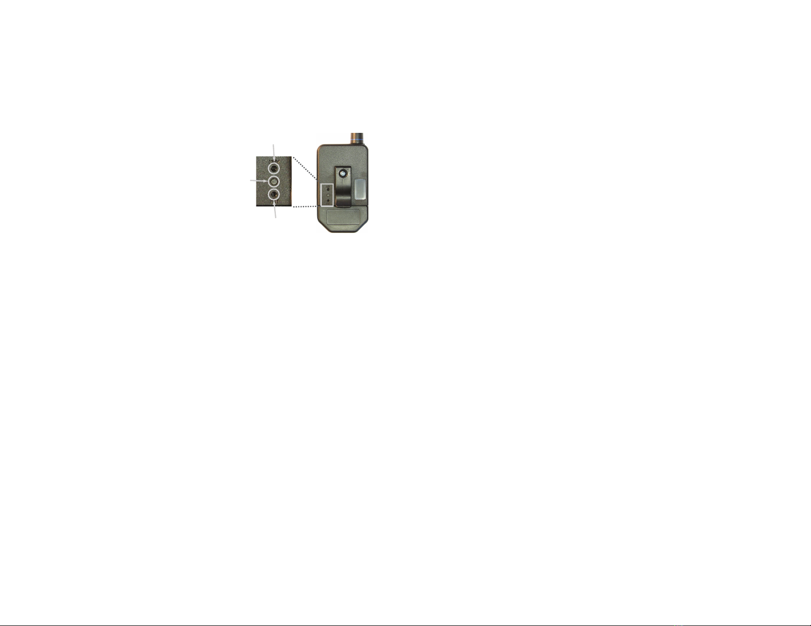
1. Create an exchange a key from
a decoder to the transmitter.
The handheld transmitter includes
an on-board infrared receiver
designed to optically receive
the decoder’s key transmission.
Sending the key in this manner
preserves security while
avoiding the need for a hardwire
connection.
The high security key is created and exchanged by placing the decoder
in the Create Key Mode. The decoder’s MODE_IND LED lights to
indicate that the decoder has entered Create Key Mode. The decoder’s
CREATE_KEY button is then pressed ten times to create the key. After
the tenth press, the MODE_IND LED turns off and the decoder outputs
the key via a 900nm infrared diode on the KEY_OUT line. A paper clip
is used to press the GET_KEY button on the back of the transmitter.
Hold the back of the transmitter near the decoder’s infrared diode
within twenty seconds. Once the key has been transferred, the MODE_
IND LEDs on both the transmitter and decoder illuminate to indicate
success.
2. Establish Control Permissions
Next, the user defines which buttons on the transmitter should be
acknowledged by the decoder. The HS Series Control Permissions
allow each transmitter in a system to activate different data lines.
This is especially useful in applications where differing user access or
activation capabilities are desired.
Consider this example: a three-door garage houses Dad’s Corvette,
Mom’s Mercedes, and Son’s Yugo. With most competitive products,
any keyfob could open any garage door as long as the addresses
match. In an HS-based system, the keyfobs could easily be configured
GET_KEY Button
CREATE_PIN
Button
MODE_IND
Window
Figure 5: Button Access Holes
to open only certain doors (guess which one Son gets to open!).
Setting the control permissions is intuitive. The user presses the
decoder’s LEARN button. The decoder’s MODE_IND LED starts
flashing and the user simply presses the handheld transmitter buttons
that should be recognized. Control Permissions are stored when
the LEARN button is pressed again or automatically after seventeen
seconds.
There are other powerful options, such as programming a user PIN or
copying a decoder, but these two steps are all that is required for a
typical setup.
Using the Optional Keypad Pin
For higher security applications, the HS Series encoder has the option to
set a Personal Identification Number (PIN) to control access to the encoder.
This PIN is a four-button combination of the eight buttons which must be
entered before the transmitter will send any commands. It needs to be
re-entered after fifteen minutes of inactivity. If no PIN is created, then the
transmitter activates as soon as a button is pressed.
Creation of a Keypad PIN
1. Use a paper clip to press the CREATE_PIN button on the back of the
transmitter. The MODE_IND LED begins flashing until either a PIN is
successfully entered or fifteen seconds has passed.
2. To enter the PIN, press a sequence of any four buttons. The MODE_
IND stops flashing and the PIN is created.
3. To cancel Create PIN Mode prior to the fourth entry, either wait for the
fifteen second timeout to pass or press the CREATE_PIN button. The
MODE_IND LED stops flashing and no PIN is created.
4. If a new KEY is created, the PIN is automatically erased.
Using the PIN
1. The PIN is entered by pressing each button until all four entries have
been made. There is a maximum two-second time limit between
entries, after which the PIN must be re-entered in its entirety.
2. Once the PIN is successfully entered, the transmitter is operational
unless it is inactive for fifteen minutes, in which case the PIN must be
re-entered.
– – – –
8 9
Contention Considerations
It is important to understand that only one transmitter at a time can be
activated within a reception area. While the transmitted signal consists
of encoded digital data, only one carrier of any particular frequency can
occupy airspace without contention at any given time. If two transmitters
are activated in the same area at the same time, then the signals will
interfere with each other and the decoder will not see a valid transmission,
so it will not take any action.
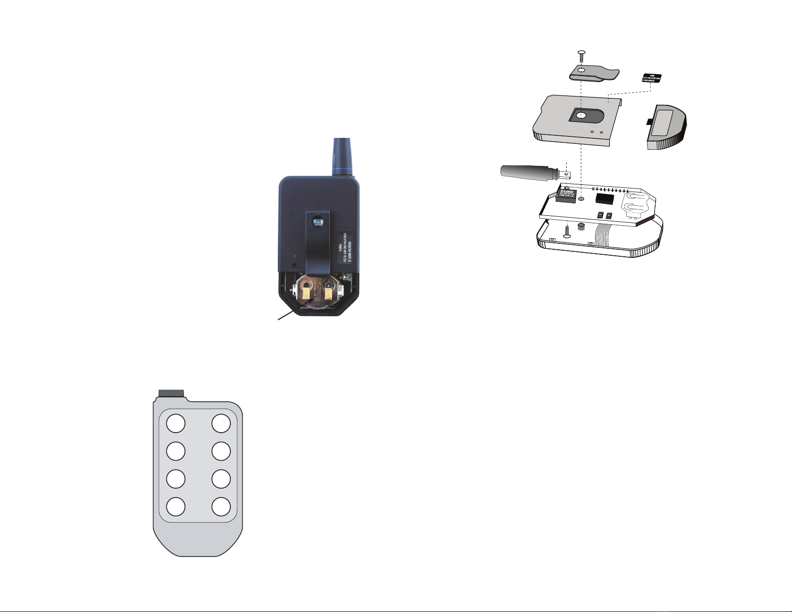
Battery Replacement
The remote unit utilizes a standard CR2032 lithium
button cell. In normal use, it provides 1 to 2 years of
operation. To replace the battery, remove the access
cover by pressing firmly on the label area and sliding it
off. Once the unit is open, remove the battery by sliding
it from beneath the holder. Replace it with the same
type of battery while observing the polarity shown in
Figure 6.
There may be the risk of explosion if the battery is
replaced by the wrong type.
OTX-***-HH-CP8-HS Button Assignments
Figure 7 illustrates the relationship between the button locations and
encoder data lines.
Assembly Diagram
D6 D7
D4 D5
D2 D3
D0 D1
FCC ID: OJM-OTX-XXX-LRMSA
IC: 5840A-LRMSXXXA
418MHz
Figure 8: OTX-***-HH-LR8-HS Assembly
Figure 6: Battery Access
Figure 7: OTX-***-HH-LR8-HS Button Assignments
+
Battery access
– – – –
10 11
GND
GND
VCC
NC
1
NC
2
NC
3
GND
4
VCC
5
PDN
6
RSSI
7
DATA
8NC 9
NC 10
NC 11
NC 12
NC 13
NC 14
GND 15
ANT 16
RXM-***-LR
220 100k
D6
D7
SEL_BAUD
SEND_COPY
GND
GND
COPY_IN
CREATE_KEY
KEY_OUT
MODE_IND
D5
D4
D3
D2
VCC
VCC
D1
D0
DATA_IN
LEARN
1
2
3
4
5
6
7
8
9
10 11
12
13
14
15
16
17
18
19
20
LICAL-DEC-HS001
From Copy Input Port
100k
100k
GND
GND
GND
VCC
VCC
VCC
GND
220
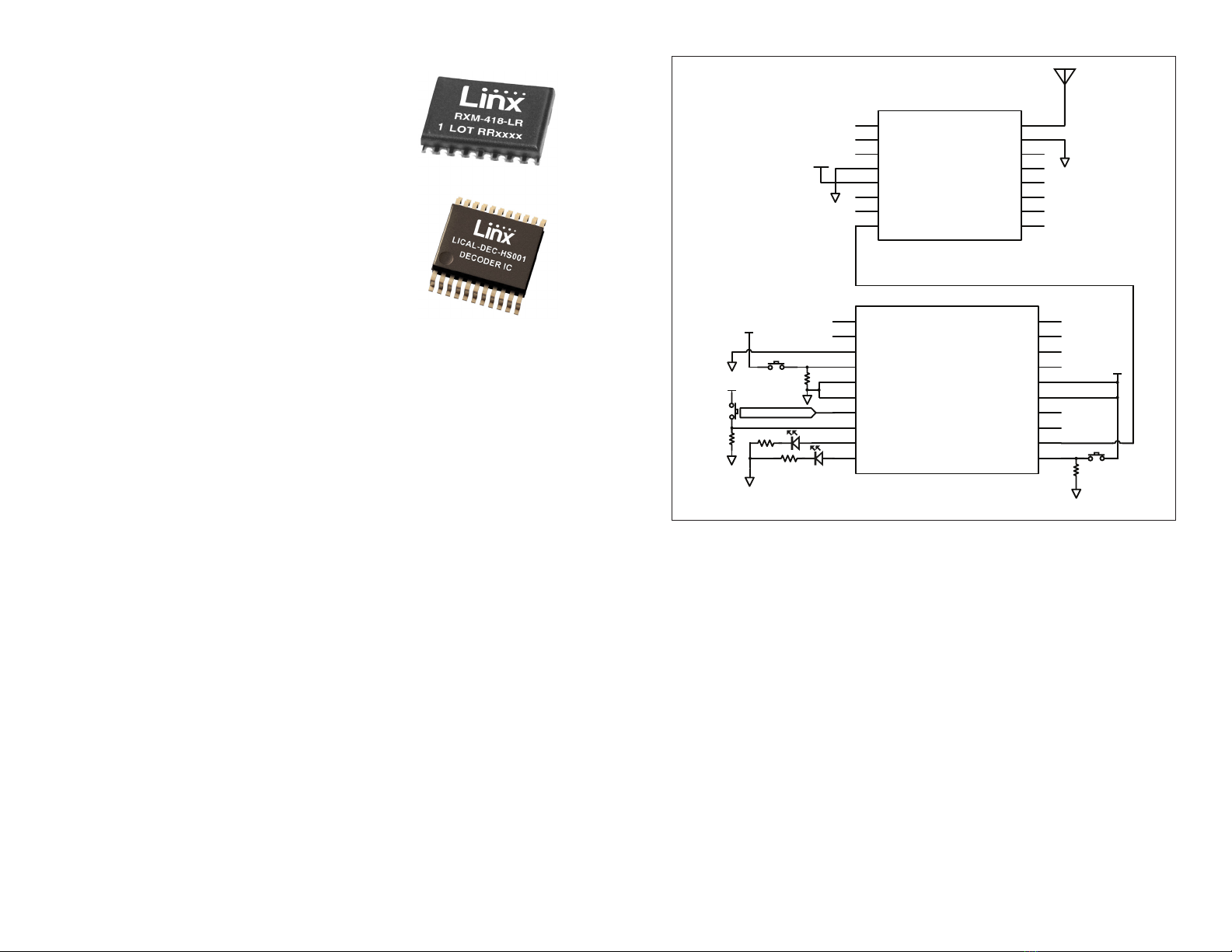
Figure 10: LR Receiver and HS Decoder Schematic
Typical Applications
The signal sent by the HS Long-Range Handheld
Transmitter can be received by the LR Series
receiver module or the LT Series transceiver
module. The outstanding sensitivity of the LR Series
receiver offers the best range when used with a
Linx OEM transmitter. The receiver module is then
connected directly to an HS Series decoder, which
decrypts the transmitted signal.
When a button is pressed on the transmitter, a
corresponding line on the decoder goes high. This
is then connected to external circuitry to perform
whatever function is required by the application.
The transmitter and decoder must be synchronized before they can work
together. This is done by creating a new encryption key in the decoder,
then transferring it to the transmitter as previously described.
Figure 10 shows a schematic for a typical receiver application. The
handheld transmitter is set to 4,800bps, so the decoder’s SEL_BAUD line
needs to be tied low.
The decoder has several unique features, such as Send Copy, and TX_ID.
As the name suggests, “Send Copy” allows the users and associated
Control Permissions of one HS Series decoder to be transferred to another.
This is useful if the same users and permissions are desired at multiple
locations, such as the front door and back door of a building. Please see
the HS Series Decoder Data Guide for more information on this feature.
The TX_ID line outputs a number associated with the originating transmitter
/ encoder. Linx Application Note AN-00156 shows how to use this feature.
Data guides for the LR Series receiver, the HS encoder, and the HS
decoder can be found on the Linx Technologies website at
www.linxtechnologies.com.
Figure 9: Receiver and Decoder
– – – –
12 13
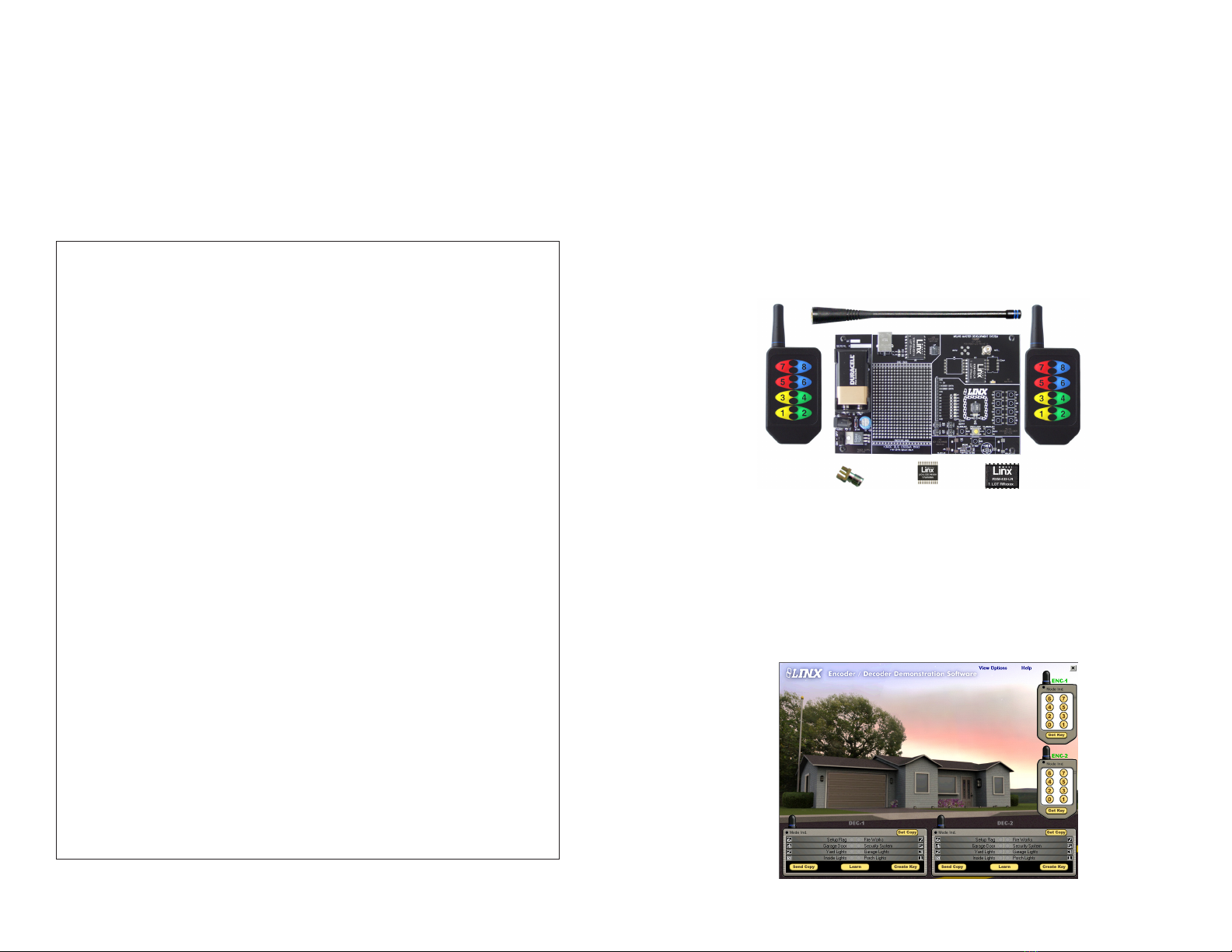
Master Development System
The Master Development System gives a designer all the tools necessary
to incorporate the HS Long-Range Handheld transmitter, LR Series
receiver, and HS Series decoder into a product. The Master Development
System serves several important functions. It allows the performance
and features of the transmitter, LR Series and HS Series to be quickly
evaluated. It shows how to design with the receiver and decoder and how
to interface with other components. It also demonstrates the overall system
function, making it easy to develop the initial system design. It allows for
additional circuitry to be placed directly on the board so that it can act
as the first prototype of the product. All of the signals are available on a
wire-wrap header for easy connection to external circuitry.
When the decoder board is plugged into a USB port on a PC, the kit can
be used to activate the features in the included software. When a data
line goes high on the decoder, a microcontroller sends a command to
the computer via a Linx USB interface module to control functions in the
software. Please see the documentation included with the Development
System for details.
Figure 11: OTX-***-HH-CP8-HS Master Development System
Figure 12: The HS Series Master Development System
Labeling / Instruction Requirements
The transmitter has been pre-certified for FCC Part 15 and Industry Canada
license-exempt RSS standards for an intentional radiator. The 433.92MHz
version has also been tested for CE compliance for use in the European
Union. The 315MHz and 418MHz versions are not legal for use in Europe.
It has already been labeled in accordance with FCC, Industry Canada
and CE regulations. No further labeling of the unit is needed; however,
it is necessary to include the following statement in the end product’s
instruction manual or insert card. EU does not require a statement.
INSTRUCTION TO THE USER
This device complies with Part 15 of the FCC Rules and Industry Canada license-
exempt RSS standard(s). Operation of this device is subject to the following two
conditions:
1. This device may not cause harmful interference, and
2. This device must accept any interference received, including interference
that may cause undesired operation.
This equipment has been tested and found to comply with the limits for a Class B
digital device, pursuant to Part 15 of the FCC Rules. These limits are designed to
provide reasonable protection against harmful interference in a residential installation.
This equipment generates, uses and can radiate radio frequency energy and, if not
installed and used in accordance with the instructions, may cause harmful interference
to radio communications. However, there is no guarantee that interference will not
occur in a particular installation. If this equipment does cause harmful interference to
radio or television reception, which can be determined by turning the equipment off
and on, the user is encouraged to try to correct the interference by one or more of the
following measures:
• Reorient or relocate the receiving antenna.
• Increase the separation between the equipment and receiver.
• Connect the equipment into an outlet on a circuit different from that to which the
receiver is connected.
• Consult the dealer or an experienced radio / TV technician for help.
Theuseriscautionedthatchangesandmodicationsmadetotheequipmentwithout
the approval of manufacturer could void the user’s authority to operate this equipment.
Le présent appareil est conforme aux CNR d'Industrie Canada applicables aux
appareils radioexempts de licence. L'exploitation est autorisée aux deux conditions
suivantes : (1) l'appareil ne doit pas produire de brouillage, et (2) l'utilisateur de
l'appareil doit accepter tout brouillage radioélectrique subi, même si le brouillage est
susceptible d'en compromettre le fonctionnement.

– – – –
14 15
Resources
Support
For technical support, product documentation, application notes, regulatory
guidelines and software updates, visit www.linxtechnologies.com
RF Design Services
For customers who need help implementing Linx modules, Linx offers
design services including board layout assistance, programming,
certification advice and packaging design. For more complex RF solutions,
Apex Wireless, a division of Linx Technologies, creates optimized designs
with RF components and firmware selected for the customer’s application.
Call +1 800 736 6677 (+1 541 471 6256 if outside the United States) for
more information.
Antenna Factor Antennas
Linx’s Antenna Factor division has the
industry’s broadest selection of antennas
for a wide variety of applications. For
customers with specialized needs, custom
antennas and design services are available along with simulations of
antenna performance to speed development. Learn more at
www.linxtechnologies.com.
VCC
R1
100k
SW1
1SW2
2SW3
3SW4
4SW5
5SW6
6SW7
7SW8
8COM
9SM1
R2
100K
VCC
1
23
4
U3
DPAK-X2
VCC
GND
GND
1
23
4
U5
DPAK-X2
1
23
4
U4
DPAK-X2
VCC
VCC
GND
GND
GND
S1
GND
D1
LED
R3
200
GND
R4
100K
GND
R5
100K
R6
100K
R7
100K
R8
100K
R9
100K
R10
100K
R11
100K
VCC
GND
B1
BAT-LINX2032
ANT1
ANTENNA
1
23
4
U2
DPAK-X2
GND
1
DATA IN
2
GND
3
LADJ/VCC
4RF OUT 5
GND 6
VCC 7
PDN 8
TX1
TXM-***-LR
GND
GND
GND
R13
C1
4.7uF
D6
D7
SEL_BAUD
SEL_TIMER
GND
GND
KEY_IN
TX_CNTL
DATA_OUT
MODE_IND CREATE_PIN
SEND
D0
D1
VCC
VCC
D2
D3
D4
D5
U1
LICAL-ENC-MSHS
C3
4.7uF
C2
10pF
GND
GND
AOUT
1
AIN-
2
AIN+
3
GND
4CIN+ 5
CIN- 6
COUT 7
VCC 8
U6
TLV2302
R21
100k
VCC
R18
9.1M
R20
51k
C5
0.01uF
VCC
VCC
GND
GND
GND
GND
C4
4.7uF
R16
9.1M
R15
9.1M
R19
10k
R14
5.1M
R17
9.1M
IR1
PS1102
S2
GND
R22
100k
Set for FCC
Compliance
Figure 13: OTX-***-HH-LR8-HS Schematic Diagram

Disclaimer
Linx Technologies is continually striving to improve the quality and function of its products. For this reason, we
reserve the right to make changes to our products without notice. The information contained in this Data Guide
is believed to be accurate as of the time of publication. Specifications are based on representative lot samples.
Values may vary from lot-to-lot and are not guaranteed. “Typical” parameters can and do vary over lots and
application. Linx Technologies makes no guarantee, warranty, or representation regarding the suitability of any
product for use in any specific application. It is the customer’s responsibility to verify the suitability of the part for
the intended application. NO LINX PRODUCT IS INTENDED FOR USE IN ANY APPLICATION WHERE THE SAFETY
OF LIFE OR PROPERTY IS AT RISK.
Linx Technologies DISCLAIMS ALL WARRANTIES OF MERCHANTABILITY AND FITNESS FOR A PARTICULAR
PURPOSE. IN NO EVENT SHALL LINX TECHNOLOGIES BE LIABLE FOR ANY OF CUSTOMER’S INCIDENTAL OR
CONSEQUENTIAL DAMAGES ARISING IN ANY WAY FROM ANY DEFECTIVE OR NON-CONFORMING PRODUCTS
OR FOR ANY OTHER BREACH OF CONTRACT BY LINX TECHNOLOGIES. The limitations on Linx Technologies’
liability are applicable to any and all claims or theories of recovery asserted by Customer, including, without
limitation, breach of contract, breach of warranty, strict liability, or negligence. Customer assumes all liability
(including, without limitation, liability for injury to person or property, economic loss, or business interruption) for
all claims, including claims from third parties, arising from the use of the Products. The Customer will indemnify,
defend, protect, and hold harmless Linx Technologies and its officers, employees, subsidiaries, affiliates,
distributors, and representatives from and against all claims, damages, actions, suits, proceedings, demands,
assessments, adjustments, costs, and expenses incurred by Linx Technologies as a result of or arising from any
Products sold by Linx Technologies to Customer. Under no conditions will Linx Technologies be responsible for
losses arising from the use or failure of the device in any application, other than the repair, replacement, or refund
limited to the original product purchase price. Devices described in this publication may contain proprietary,
patented, or copyrighted techniques, components, or materials. Under no circumstances shall any user be
conveyed any license or right to the use or ownership of such items.
©2015 Linx Technologies. All rights reserved.
The stylized Linx logo, Wireless Made Simple, WiSE, CipherLinx and the stylized CL logo are trademarks of Linx Technologies.
Linx Technologies
159 Ort Lane
Merlin, OR, US 97532
Phone: +1 541 471 6256
Fax: +1 541 471 6251
www.linxtechnologies.com
This manual suits for next models
2
Other Linx Technologies Transmitter manuals


