manuals.online logo
Brands
  1. Home
  2. •
  3. Brands
  4. •
  5. M-system
  6. •
  7. Transmitter
  8. •
  9. M-system B3FR User manual

M-system B3FR User manual

Other M-system Transmitter manuals

M-system M3LU User manual

M-system

M-system M3LU User manual

M-system MXS User manual

M-system

M-system MXS User manual

M-system B3VS/2 User manual

M-system

M-system B3VS/2 User manual

M-system W2RS1 User manual

M-system

M-system W2RS1 User manual

M-system W5MS User manual

M-system

M-system W5MS User manual

M-system M5XREB User manual

M-system

M-system M5XREB User manual

M-system B5VS User manual

M-system

M-system B5VS User manual

M-system M5XCRS User manual

M-system

M-system M5XCRS User manual

M-system Mini-M M2RS1 User manual

M-system

M-system Mini-M M2RS1 User manual

M-system Mini-M M2DY User manual

M-system

M-system Mini-M M2DY User manual

M-system M5MS-5-R User manual

M-system

M-system M5MS-5-R User manual

M-system 10SP User manual

M-system

M-system 10SP User manual

M-system 6BR User manual

M-system

M-system 6BR User manual

M-system 10RS User manual

M-system

M-system 10RS User manual

M-system 10PA User manual

M-system

M-system 10PA User manual

M-system M5VS Series User manual

M-system

M-system M5VS Series User manual

M-system M6SVS User manual

M-system

M-system M6SVS User manual

M-system M6DVF User manual

M-system

M-system M6DVF User manual

M-system W5FV User manual

M-system

M-system W5FV User manual

M-system W2PA User manual

M-system

M-system W2PA User manual

M-system MFS2 User manual

M-system

M-system MFS2 User manual

M-system M1EXS-2 User manual

M-system

M-system M1EXS-2 User manual

M-system B5RS User manual

M-system

M-system B5RS User manual

M-system MXLC User manual

M-system

M-system MXLC User manual

Popular Transmitter manuals by other brands

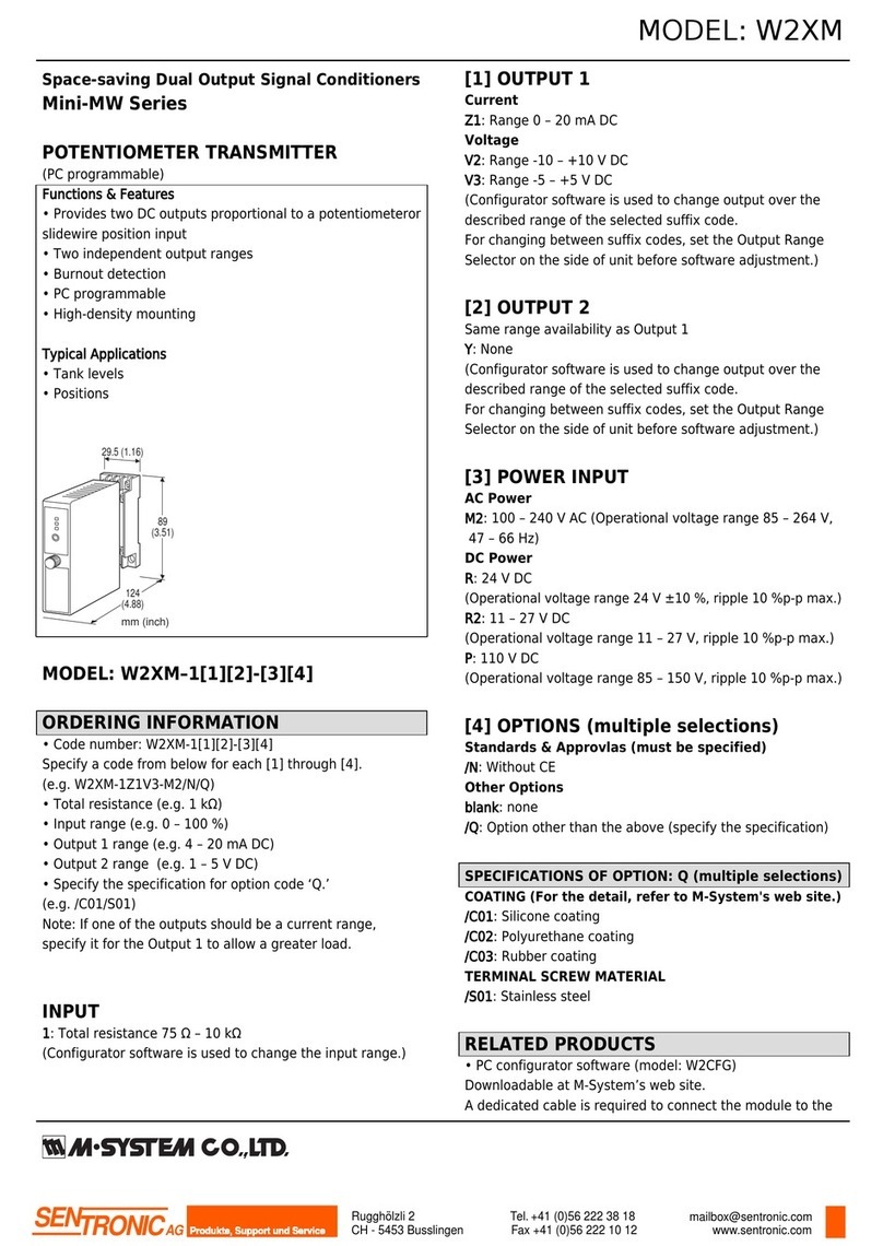
Seneca K120RTD installation manual

Seneca

Seneca K120RTD installation manual

Nautel GV40 installation manual

Nautel

Nautel GV40 installation manual

HumanTechnik cm-light operating instructions

HumanTechnik

HumanTechnik cm-light operating instructions

INOR APAQ C130 TC User instructions

INOR

INOR APAQ C130 TC User instructions

Linear DXS-64 operating instructions

Linear

Linear DXS-64 operating instructions

FeinTech ABT00102 instruction manual

FeinTech

FeinTech ABT00102 instruction manual

Geo Web Pack quick start guide

Geo

Geo Web Pack quick start guide

Inovonics EchoStream EN1210W installation instructions

Inovonics

Inovonics EchoStream EN1210W installation instructions

IKONNIK KA-6 quick start guide

IKONNIK

IKONNIK KA-6 quick start guide

Rohde & Schwarz SR8000 Series System manual

Rohde & Schwarz

Rohde & Schwarz SR8000 Series System manual

Audio Technica UniPak ATW-T93 Installation and operation

Audio Technica

Audio Technica UniPak ATW-T93 Installation and operation

NIVELCO EasyTREK SCA-300 Series Programming manual

NIVELCO

NIVELCO EasyTREK SCA-300 Series Programming manual

Honeywell 5816WMBR installation instructions

Honeywell

Honeywell 5816WMBR installation instructions

Kamstrup READy MTU Installation and operation guide

Kamstrup

Kamstrup READy MTU Installation and operation guide

Omega ZW Series user guide

Omega

Omega ZW Series user guide

ABB Field 264H Instructions for installation

ABB

ABB Field 264H Instructions for installation

Dejero EnGo 3x manual

Dejero

Dejero EnGo 3x manual

Rosemount 4600 Reference manual

Rosemount

Rosemount 4600 Reference manual

manuals.online logo
manuals.online logoBrands
  • About & Mission
  • Contact us
  • Privacy Policy
  • Terms and Conditions

Copyright 2025 Manuals.Online. All Rights Reserved.

B3FR
P. 1 / 4
EM-7514 Rev.6
5-2-55, Minamitsumori, Nishinari-ku, Osaka 557-0063 JAPAN
Phone: +81(6)6659-8201 Fax: +81(6)6659-8510 E-mail: info@m-system.co.jp
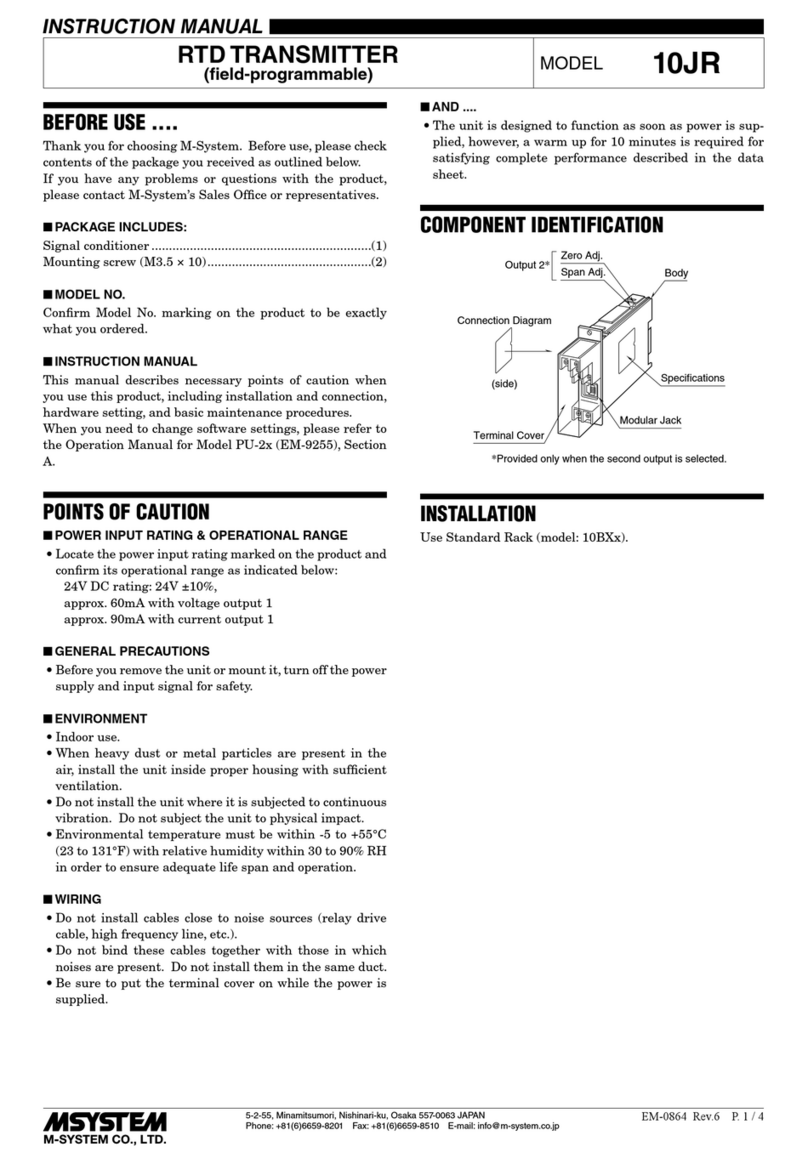
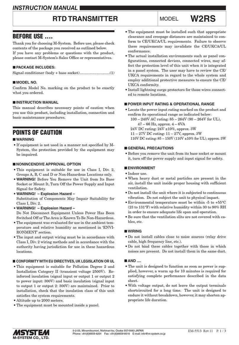
RTD TRANSMITTER
(eld-congurable) MODEL B3FR
INSTRUCTION MANUAL
BEFORE USE ....
Thank you for choosing M-System. Before use, please check
contents of the package you received as outlined below.
If you have any problems or questions with the product,
please contact M-System’s Sales Office or representatives.
■PACKAGE INCLUDES:
Signal conditioner......................................................... (1)
■MODEL NO.
Confirm Model No. marking on the product to be exactly
what you ordered.
■INSTRUCTION MANUAL
This manual describes necessary points of caution when
you use this product, including installation, connection and
basic maintenance procedures.
POINTS OF CAUTION
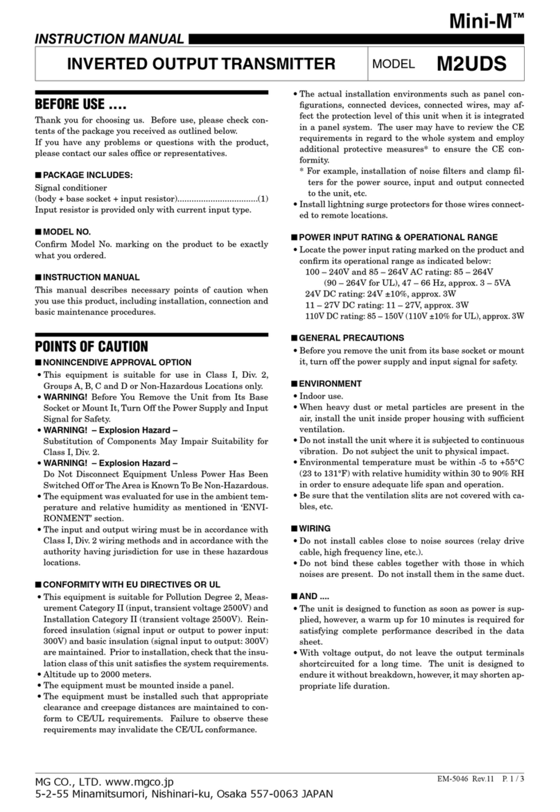
■CONFORMITY WITH UL
•ThisequipmentissuitableforuseinaPollutionDegree2
environment.
•DONOT connecttheRTDtocircuitsgreaterthan30V
rmsand42.4Vpeakor60VDC.
•Thisequipmentistobeusedwiththemaximumoperat-
ingvoltage30Vrmsand42.4Vpeakor60VDC.
•Theequipmentmustbemountedinsideasuitablereen-
closure.
•Operatingtemperature:-40to+55°C(-40to+131°F)
•Altitudeupto2000meters.
■CONFORMITY WITH EU DIRECTIVES
•Functionalinsulationismaintainedbetweensignalinput
and output.
•Theequipmentmustbemountedinsideapanel.
•Installlightningsurgeprotectorsforthosewiresconnected
to remote locations.
•Insertanoiselterforinputandoutputconnectedtothe
unit.TDKNoiseFilterModelZCAT3035-1330orequiva-
lent is recommended.
•The actual installation environments such as panel con-
figurations, connected devices, connected wires, may affect
the protection level of this unit when it is integrated in a
panel system. The user may have to review the CE require-
ments in regard to the whole system and employ additional
protective measures to ensure the CE conformity.
■SAFETY PRECAUTION
Before you remove the unit or mount it, turn off the power
supply and input signal for safety.
■ENVIRONMENT
•Indooruse
•Whenheavydustormetalparticlesarepresentintheair,
install the unit inside proper housing with sufficient ven-
tilation.
•Donotinstalltheunitwhereitissubjectedtocontinuous
vibration.Donotsubjecttheunittophysicalimpact.
•Environmentaltemperaturemustbewithin-40to+85°C
(-40to+185°F)withrelativehumiditywithin0to95%RH
in order to ensure adequate life span and operation.
•Besurethattheventilationslitsarenotcoveredwithca-
bles, etc.
■WIRING
•Do not install cables close to noise sources (relay drive
cable, high frequency line, etc.).
•Do not bind these cables together with those in which
noisesarepresent.Donotinstalltheminthesameduct.
■AND ....
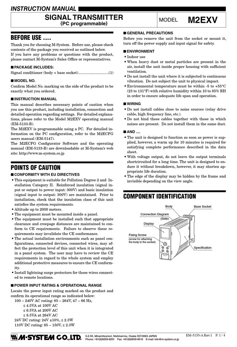
The unit is designed to function as soon as power is sup-
plied,however,awarmupfor10minutesisrequiredforsat-
isfying complete performance described in the data sheet.
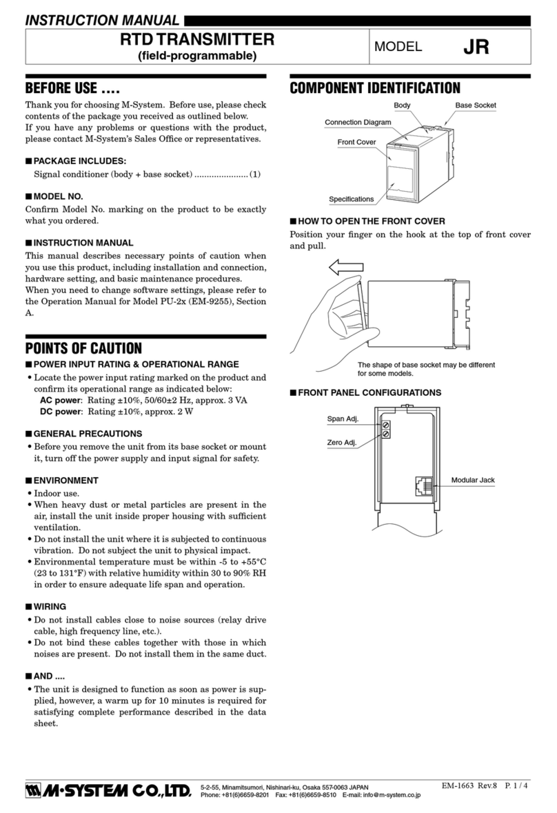
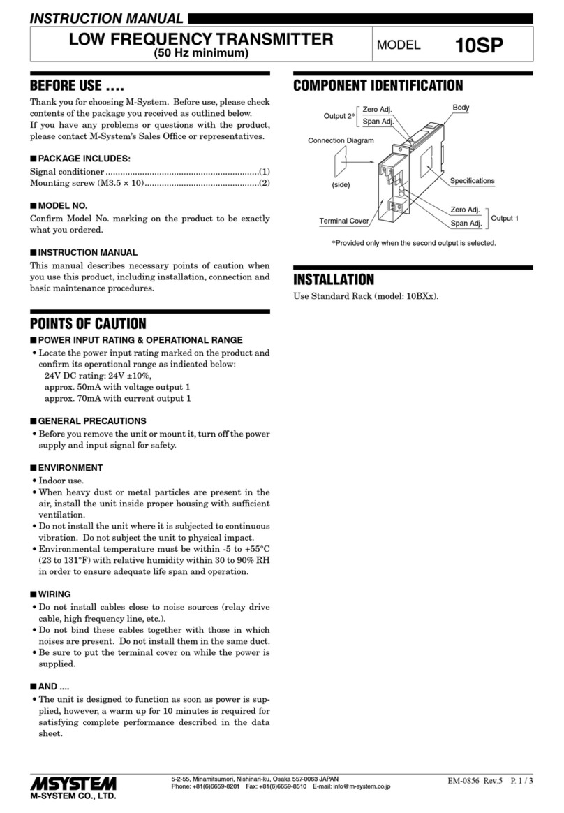
COMPONENT IDENTIFICATION
■HOW TO OPEN THE COVER WHEN SETTING DIP SW
Holdatthetopandbottomoftheunitasshownbelowand
slide the housing cover gently to open until it hits the latch-
ing inside the unit.
Body
SW Configuration
Zero Adj.
Span Adj.
Specifications
(side)
• Housing Cover Fully Opened
Caution: DO NOT PULL beyond where the housing cover is latched.
The plastic housing may be damaged.
B3FR
P. 2 / 4
EM-7514 Rev.6
5-2-55, Minamitsumori, Nishinari-ku, Osaka 557-0063 JAPAN
Phone: +81(6)6659-8201 Fax: +81(6)6659-8510 E-mail: info@m-system.co.jp
■HOW TO SEPARATE THE TERMINAL BLOCKS
When you need to separate the terminal blocks from the
transmitter body for wiring, insert a minus driver between
the terminal block and the housing body, pull up the driver
and pull out the terminal block.
INSTALLATION
■DIN RAIL MOUNTING
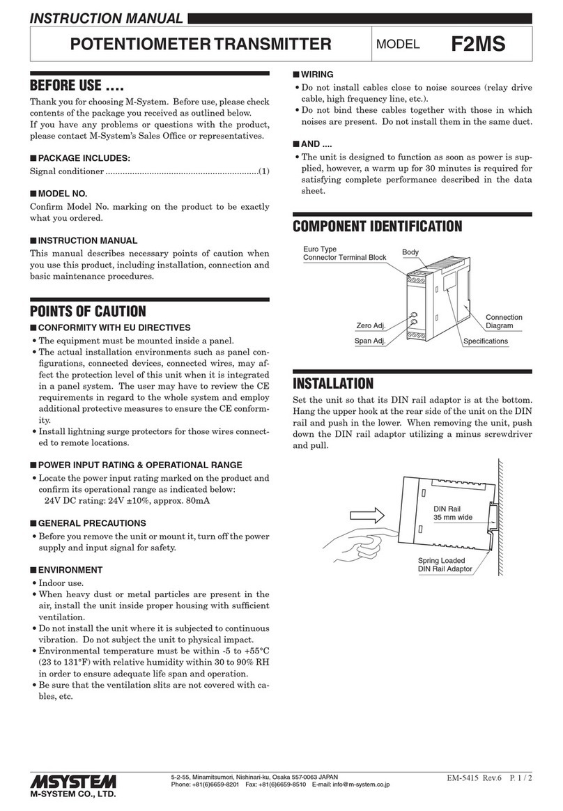
SettheunitsothatitsDINrailadaptorisatthebottom.
Positiontheupperhookattherearsideoftheunitonthe
DINrailandpushinthelower.Whenremovingtheunit,
push down the DIN rail adaptor utilizing a minus screw-
driver and pull.
DIN Rail
35mm wide
Spring Loaded
DIN Rail Adaptor
12
mA
MONITOR
–
+
–
LOAD
11
10
OUTPUT
24 V DC
4 – 20 mA DC
*
* DC ammeter’s internal resistance 10 ohms max.
6
5
4
B
B
A
RTD
EXTERNAL VIEWS
1
4
6
3
5
2
ON
1
SW2
SW3
2345678
Input Config. DIP SW
Input Config. Rotary SW
10 11 12
456
Zero Adj.
Span Adj.
■ FRONT VIEW ■ SIDE VIEW
SW1
TERMINAL CONNECTIONS
Connect the unit as in the diagram below.
■WIRING INSTRUCTIONS
 •Applicablewiresize
  Solid: 0.2to2.5mm2(0.55to1.75dia.)
  Stranded: 0.2to2.5mm2
Tinning wire ends may cause contact failure
and therefore is not recommended.
  Ferruled: 0.2to1.5mm2(0.55to1.35dia.)
    ThefollowingPhoenixContactterminalsare
   recommended:
    AI0,25-8YE 0.2to0.25mm2
    AI0,34-8TQ 0.25to0.34mm2
    AI0,5-8WH 0.34to0.5mm2
    AI0,75-8GY 0.5to0.75mm2
    AI1,0-8RD  0.75to1.0mm2
    AI1,5-8BK  1.0to1.5mm2
 •Exposewireconductorsby8mm(0.31”).
8 mm 8 mm
4 mm dia.
max.
4 mm dia.
max.
Wire exposure Recommended
ferruled wire
B3FR
P. 3 / 4
EM-7514 Rev.6
5-2-55, Minamitsumori, Nishinari-ku, Osaka 557-0063 JAPAN
Phone: +81(6)6659-8201 Fax: +81(6)6659-8510 E-mail: info@m-system.co.jp
■GENERAL PROCEDURE
FirstselectacoarserangeusingtheinternalDIPswitches(SW1,SW2andSW3)accordingtoTables1through4below.
Thenapplysimulated0%and100%inputsandne-tunetheoutputrangeto4mAand20mAusingthefrontzeroandspan
adjustments.
DIPSWsettingcanbechangedwhilethepowerisappliedtothetransmitter.Linearizationandzero/spanadjustmentswill
not perform correctly with inaccurate switch configuration but it will not damage the unit in anyway.
■ SELECTING DIP SW (coarse adjustment)
INPUT TYPE & RANGE
Choose the desired range (usable range = highest span selectable) according to Table 1. The minimum span requirements in
the table must be met when choosing the desired range.
Table 1 ■= ON
RTD USABLE RANGE MIN. SPAN SW1 SW2
12345678
Pt100(JIS‘97,IEC) -50to+750°C -58to+1382°F 300°C 540°F 1■ ■
-50to+350°C -58to+662°F 100°C 180°F 2 ■ ■
-50to+150°C -58to+302°F 50°C 90°F 3 ■ ■
Ni120 -50to+200°C -58to+392°F 100°C 180°F 4■ ■
-50to+100°C -58to+212°F 50°C 90°F 5 ■ ■
Cu10@25°C -50to+250°C -58to+482°F 100°C 180°F 6 ■ ■
BURNOUT
SeeTable2.
Table 2 ■= ON
BURNOUT SW3
5678
Upscale ■ ■
Downscale ■ ■
No burnout
GAIN
SeeTable3.
Thegainisdenedbythefollowingequation:
[Span of usable range]
 Gain=–––––––––––––––––––––––×100(%)
[Span of calibration range]
where
 [Spanofusablerange](°C)
   =[Max.valueofusablerange]–(-50*1)
 [Spanofcalibrationrange](°C)
   =[100%inputtemp.]–[0%inputtemp.]
*1.-58for°F
Table 3 ■= ON
GAIN SW2
123
267%<Gain≤400% ■
167%<Gain≤267% ■
100%≤Gain≤167% ■
OFFSET
See Table 4.
Theoffsetisdenedbythefollowingequation:
    [0%inputtemp.]–(-50*1)
 Offset=–––––––––––––––––––––––×100(%)  
[Span of calibration range]
*1.-58for°F
Table 4 ■= ON
OFFSET SW3-4
Factorydefaultsetting ■
Offset ≥ 26%*2 and when 0% output cannot be
calibratedwithzeroadjustment.*2.28%forNi120.
EXAMPLE
Pt100,0–90°C,Upscaleburnout
1) SensortypeandRange:AccordingtoTable1,choose‘Pt
100,-50–+150°C’range.
➠SetSW1to‘3,’SW2-1andSW2-6toON.
2) Burnout:AccordingtoTable2,choose‘Upscale.’
➠SetSW3-5andSW3-7toON.
3) Gain
[150–(-50)]
 –––––––––––×100=222(%)
 [90–0]
➠AccordingtoTable3,setSW3-2toON.
4) Offset
[0–(-50)]
 –––––––––––×100=25(%)
 [150–(-50)]
➠AccordingtoTable4,SW3-4remainsOFF.
■ ZERO & SPAN ADJUSTMENTS (ne adjustments)
Referring to ‘ADJUSTMENT PROCEDURE’ in the next
page,apply0%and100%inputsignalsandadjusttheZero
tohave4 mA output and Span tohave20 mA output re-
spectively.
ON ON
1
SW2
2345678
1
SW3
2345678
SW1
1
4
6
3
5
2
RANGE CONFIGURATION
B3FR
P. 4 / 4
EM-7514 Rev.6
5-2-55, Minamitsumori, Nishinari-ku, Osaka 557-0063 JAPAN
Phone: +81(6)6659-8201 Fax: +81(6)6659-8510 E-mail: info@m-system.co.jp
ADJUSTMENT PROCEDURE
This unit is calibrated at the factory to meet the ordered
specifications, therefore you usually do not need any cali-
bration.
Formatchingthesignaltoareceivinginstrumentorincase
ofregularcalibration,adjusttheoutputasexplainedinthe
following.
■HOW TO CALIBRATE THE OUTPUT SIGNAL
Use a signal source and measuring instruments of sufficient
accuracy level. Turn the power supply on and warm up for
morethan10minutes.
1) ZERO:Apply0%inputandadjustoutputto0%.
2) SPAN:Apply100%inputandadjustoutputto100%.
3) CheckZEROadjustmentagainwith0%input.
4) When ZERO value is changed, repeat the above proce-
dure1)–3).
MAINTENANCE
Regularcalibrationprocedureisexplainedbelow:
■CALIBRATION
Warmuptheunitforatleast10minutes.Apply0%,25%,
50%, 75% and 100% input signal.  Check that the output
signal for the respective input signal remains within accu-
racydescribedinthedatasheet.Whentheoutputisoutof
tolerance, recalibrate the unit according to the“ADJUST-
MENTPROCEDURE”explainedearlier.
CHECKING
1) Terminalwiring:Checkthatallcablesarecorrectlycon-
nected according to the connection diagram.
2)DIPSWsetting:Checkthattheswitchesaresettoap-
propriate positions.
3) Input:  Checkvoltageacrosstheterminal4–5witha
sensitive voltmeter.
 (With20°Cor68°F,approx.110mVwithPt100,approx.
140mVwithNi120,approx.10mVwithCu10.)
 IftheRTDoritsextensionwiresarebroken,theoutput
goes over 100% (below 0% with downscale protection)
due to burnout function. Check leadwires in such a case.
4) Output:  Check that the loadis within the permissible
limit including wiring resistance.
    SupplyVoltage(V)–12(V)
 LoadResistance(Ω)=––––––––––––––––––––––––
     0.02(A)
(including leadwire resistance)
5) Whenyouchecktheoutputsignal,connectanammeter
of which the internal resistance is of 10 Ω max. to the
monitor terminals.
EXTERNAL DIMENSIONS mm (inch)
10 11 12
456
106 (4.17)
18 (.71) 110.5 (4.35)
62 (2.44)
[5 (.20)]
DIN RAIL
35mm wide
• When mounting, no extra space is needed between units.