manuals.online logo
Brands
  1. Home
  2. •
  3. Brands
  4. •
  5. Linx
  6. •
  7. Transmitter
  8. •
  9. Linx OTX-315-HH-KF#-MS series Instruction Manual

Linx OTX-315-HH-KF#-MS series Instruction Manual

MS Keyfob
Transmitter
Data Guide
Warning: Some customers may want Linx radio frequency (“RF”)
products to control machinery or devices remotely, including machinery
or devices that can cause death, bodily injuries, and/or property
damage if improperly or inadvertently triggered, particularly in industrial
settings or other applications implicating life-safety concerns (“Life and
Property Safety Situations”).
NO OEM LINX REMOTE CONTROL OR FUNCTION MODULE
SHOULD EVER BE USED IN LIFE AND PROPERTY SAFETY
SITUATIONS. No OEM Linx Remote Control or Function Module
should be modified for Life and Property Safety Situations. Such
modification cannot provide sufficient safety and will void the product’s
regulatory certification and warranty.
Customers may use our (non-Function) Modules, Antenna and
Connectors as part of other systems in Life Safety Situations, but
only with necessary and industry appropriate redundancies and
in compliance with applicable safety standards, including without
limitation, ANSI and NFPA standards. It is solely the responsibility
of any Linx customer who uses one or more of these products to
incorporate appropriate redundancies and safety standards for the Life
and Property Safety Situation application.
Do not use this or any Linx product to trigger an action directly
from the data line or RSSI lines without a protocol or encoder/
decoder to validate the data. Without validation, any signal from
another unrelated transmitter in the environment received by the module
could inadvertently trigger the action.
All RF products are susceptible to RF interference that can prevent
communication. RF products without frequency agility or hopping
implemented are more subject to interference. This module does not
have a frequency hopping protocol built in.
Do not use any Linx product over the limits in this data guide.
Excessive voltage or extended operation at the maximum voltage could
cause product failure. Exceeding the reflow temperature profile could
cause product failure which is not immediately evident.
Do not make any physical or electrical modifications to any Linx
product. This will void the warranty and regulatory and UL certifications
and may cause product failure which is not immediately evident.
!Table of Contents
1 Description
1 Features
1 Applications
1 OEM Congurations
2 Ordering Information
2 Electrical Specications
3 Theory of Operation
4 Setting the Transmitter Address
4 Button Assignments
5 Contention Considerations
5 Battery Replacement
5 Assembly Diagram
6 Compliance Requirements
6 Labeling / Instruction Requirements
8 Typical Applications
10 Resources
11 Notes
––
1
Description
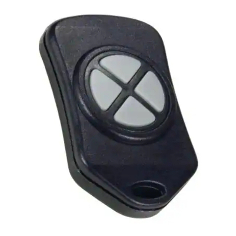
The Linx MS Series Keyfob transmitter is
ideal for remote control and command
applications. Available in 315, 418
(standard) or 433.92MHz versions, it
has been pre-certified for FCC Part 15,
Industry Canada, and European CE
(433MHz) compliance. This dramatically
reduces development cost and time
to market. The high-performance
synthesized design provides superior
frequency accuracy and minimizes body
proximity effects. When combined with an
LR or LT Series module, the Keyfob can
operate at distances of up to 750 feet.
Ease of use and security are dramatically
enhanced by the on-board MS Series
encoder, which allows instant creation of
up to 16,777,216 (224) unique addresses
without cumbersome DIP switches
or cut traces. When paired with a MS
Series decoder, Keyfob identity can be
determined and button permissions established. The Keyfob is available
with 1 to 5 buttons and can be custom labeled
Features
• FCC, IC and CE pre-certified
• Long range
• Simple user setup
• 224 unique addresses
• 1 to 5 buttons
• Compact, stylish package
Applications
• General remote control
• Keyless entry
• Garage / gate openers
• Lighting control
• Home / industrial automation
• Wire elimination
MS Keyfob Transmitter
Data Guide
Revised 9/8/14
2.23"
1.00"
0.45"
1.37"
S4
S2
S1 S3S5
Figure 1: Package Dimensions
Figure 2: Keyfob Button Configurations
OEM Congurations
With a one-time NRE and
minimum order, Linx can
configure the keypad and label
areas. Contact Linx for details.
–– – –
2 3
Ordering Information
Part Number Description
OTX-***-HH-KF#-MS-xxx MS Keyfob Transmitter
MDEV-***-HH-KF#-MS MS Keyfob Development System
*** = 315, 418 (Standard) or 433.92MHz
xxx = Color (Leave blank for standard black)
WHT = White
CRE = Red
CGY = Gray
Keyfob Electrical Specifications
Parameter Designation Min. Typ. Max. Units Notes
Power Supply
Operating Voltage VCC 2.1 3.0 3.6 VDC
Supply Current lCC 3.4 mA
Power-Down Current lPDN 5.0 nA 1
Transmitter Section
Transmit Frequency Range FC
OTX-315-HH-KF#-MS 315 MHz
OTX-418-HH-KF#-MS 418 MHz
OTX-433-HH-KF#-MS 433.92 MHz
Center Frequency Accuracy –50 +50 kHz
Data Rate 9,600 bps
Environmental
Operating Temperature Range –40 +85 °C 1
1. Characterized, but not tested
Electrical Specications
Ordering Information
Figure 3: Ordering Information
Figure 4: Electrical Specifications
Theory of Operation
The MS Series Keyfob Transmitter combines a high-performance
synthesized transmitter with an on-board MS Series encoder IC to form
a highly reliable, yet cost-effective RF remote control transmitter. The
transmitter’s advanced synthesized architecture delivers superior stability
and frequency accuracy while minimizing the effects of temperature and
body proximity.
The advanced MS Series encoder has several advantages over previous
solutions. It provides more security by offering 224 addresses, which is
several orders of magnitude greater than older encoders. Furthermore,
the address is instantly established with a simple button press, eliminating
cumbersome DIP switches and cut traces. When paired with a MS Series
decoder, keyfob identity can be determined and distinct transmitter-receiver
relationships established.
The Keyfob operates in the following manner: when a button is pressed
on the Keyfob, power is applied to the internal circuitry and the encoder IC
is enabled. The encoder then detects the logic states of the button data
lines. The encoder data is used to modulate the transmitter, which, through
the antenna, conveys the data into free space. The transmission cycle
continues until the button is released. On the receiver side, an MS Series
decoder IC is used to check the transmitter’s address bits against the
address saved in memory. If a match is confirmed, and if the decoder has
permission to recognize the specific button being pressed, the decoder’s
outputs are set to replicate the transmitter’s button states. These outputs
can then be used to activate external circuitry required by the application.
The transmitter is compatible with the LT and LR product families. When
the Keyfob transmitter is combined with an LR Series receiver and MS
Series decoder, ranges of up to 750 feet are possible. Applications
operating over shorter distances will also benefit from the increased link
reliability and superior noise immunity provided by the LR receiver.
–– – –
4 5
Setting the Transmitter Address
The address is changed by using a paper clip
or probe to press the CREATE_ADDR button
on the board through the hole in the back
of the case. When the button is depressed,
an LED lights up in the MODE_IND window,
indicating that the address is being created.
The address is randomized for as long as
the button is held down. When the button is
released, the randomized address is saved
and the LED begins flashing to indicate that
the Control Permissions may now be set.
Press the buttons that the Keyfob user will have the authority to access.
Press the CREATE_ADDR button with the paper clip again or wait 17
seconds for it to time out. The address and Control Permissions are
now set. The decoder needs to learn the address before it accepts any
transmissions. Please see the Typical Applications section of this data
guide or the MS Series Decoder Data Guide for details.
Button Assignments
The Keyfob is available in five button configurations. Those configurations
and the corresponding switch numbers are shown in Figure 6. The table
shows which encoder data line has been assigned to each switch. When a
button is pressed, the data line goes high, causing the corresponding data
line on the decoder to go high if the address has been learned.
Figure 5: CREATE_ADDR Button Access
S4
S2
S1 S3S5
S5
S2
S5
S4
S4
S2
S4
S1 S3
S2
Button Data Line
S1 D0
S2 D1
S3 D2
S4 D3
S5 D4
Figure 6: OTX-***-HH-KF#-MS Button Assignments
Contention Considerations
It is important to understand that only one transmitter at a time can be
activated within a reception area. While the transmitted signal consists
of encoded digital data, only one carrier of any particular frequency can
occupy airspace without contention at any given time. If two transmitters
are activated in the same area at the same time, then the signals will
interfere with each other and the decoder will not see a valid transmission,
so it will not take any action.
Battery Replacement
The transmitter utilizes a standard CR2032 lithium
button cell. In normal use, it provides 1 to 2 years of
operation. Access for replacement is accomplished
by gently prying apart the two halves of the Keyfob at
the seam (fingernails or a coin will do). Once the unit is
open, remove the battery by sliding it out from beneath
the retainer.
There may be the risk of explosion if the battery is
replaced by the wrong type. Replace it with the same
type of battery while observing the polarity shown in
Figure 7.
Assembly Diagram
Battery
Figure 7: Battery Access
Figure 8: OTX-***-HH-KF#-MS Assembly
CREATE_ADDR
Button Access
–– – –
6 7
Labeling / Instruction Requirements
The transmitter has been pre-certified for FCC Part 15 and Industry Canada
license-exempt RSS standards for an intentional radiator. The 433.92MHz
version has also been tested for CE compliance for use in the European
Union. The 315MHz and 418MHz versions are not legal for use in Europe.
It has already been labeled in accordance with FCC, Industry Canada
and CE regulations. No further labeling of the unit is needed; however,
it is necessary to include the following statement in the end product’s
instruction manual or insert card. EU does not require a statement.
INSTRUCTION TO THE USER
This device complies with Part 15 of the FCC Rules and Industry Canada license-
exempt RSS standard(s). Operation of this device is subject to the following two
conditions:
1. This device may not cause harmful interference, and
2. This device must accept any interference received, including interference
that may cause undesired operation.
This equipment has been tested and found to comply with the limits for a Class B
digital device, pursuant to Part 15 of the FCC Rules. These limits are designed to
provide reasonable protection against harmful interference in a residential installation.
This equipment generates, uses and can radiate radio frequency energy and, if not
installed and used in accordance with the instructions, may cause harmful interference
to radio communications. However, there is no guarantee that interference will not
occur in a particular installation. If this equipment does cause harmful interference to
radio or television reception, which can be determined by turning the equipment off
and on, the user is encouraged to try to correct the interference by one or more of the
following measures:
• Reorient or relocate the receiving antenna.
• Increase the separation between the equipment and receiver.
• Connect the equipment into an outlet on a circuit different from that to which the
receiver is connected.
• Consult the dealer or an experienced radio / TV technician for help.
Theuseriscautionedthatchangesandmodicationsmadetotheequipmentwithout
the approval of manufacturer could void the user’s authority to operate this equipment.
Le présent appareil est conforme aux CNR d'Industrie Canada applicables aux
appareils radioexempts de licence. L'exploitation est autorisée aux deux conditions
suivantes : (1) l'appareil ne doit pas produire de brouillage, et (2) l'utilisateur de
l'appareil doit accepter tout brouillage radioélectrique subi, même si le brouillage est
susceptible d'en compromettre le fonctionnement.
–– – –
8 9
Typical Applications
The signal sent by the Keyfob transmitter can be
received by the LR Series receiver module or the LT
Series transceiver module. The receiver module is
connected directly to the MS Series decoder, which
decodes the transmitted signal.
When a button is pressed on the transmitter, a
corresponding line on the decoder goes high. This
can then be connected to external circuitry to perform
whatever function is required by the application.
The decoder must learn the transmitter’s address
before they can work together. This is done by taking
the LEARN line on the decoder high, typically with a
pushbutton. The MODE_IND line starts switching (if an LED is attached,
this causes it to flash) indicating that the decoder is in Learn Mode. Press
any of the buttons on the transmitter to initiate a transmission. Take the
LEARN line high again to exit Learn Mode and the system is ready for use.
Figure 10 shows a schematic for a typical application.
Figure 9: Linx RF Modules
The Keyfob is set to 9,600bps, so SEL_BAUD0 should be tied high and
SEL_BAUD1 tied low.
The decoder has several unique features, such as Latch Mode, Receiver
Control and TX_ID.
If the LATCH line is tied to VCC, the outputs go high on the first
transmission, then low on the second. It is shown tied low, so the outputs
are momentary (high for as long as a signal is received instructing the
decoder to make them high).
The RX_CNTL line can be connected to the PDN line of the receiver and
the decoder activates the receiver with a 10% duty cycle This greatly
reduces the average current consumption of the system. The adjacent
figure shows it tied to ground, but to use this feature, connect the RX_
CNTL line of the decoder directly to the receiver’s PDN line.
The TX_ID line outputs a number associated with the originating transmitter
/ encoder. Application Note AN-00156 shows how to use this feature.
Data guides for the modules, the MS encoder, and the MS decoder can be
found on the Linx Technologies website.
G
N
D
G
N
D
V
CC
N
C
1
N
C
2
N
C
3
G
N
D
4
V
CC
5
PDN
6
R
SSI
7
DATA
8
N
C
9
N
C
1
0
N
C
11
N
C
12
N
C
1
3
N
C
14
G
N
D
1
5
ANT
1
6
RXM
-
LR
22
0
D
6
D7
SEL
_
BAUD
0
SEL
_
BAUD
1
G
N
D
G
N
D
LAT
CH
RX
_
CNT
L
TX
_
I
D
MODE_IN
D
D
5
D4
D
3
D2
V
CC
V
CC
D
1
D
0
DATA
_
I
N
LEARN
1
2
3
4
5
6
7
8
9
1
0
11
12
1
3
14
1
5
1
6
17
1
8
1
9
2
0
LI
C
AL-DE
C
-M
S001
V
CC
G
N
D
G
N
D
V
CC
Figure 10: LR Receiver and MS Decoder Schematic
–– – –
10 11
Resources
Support
For technical support, product documentation, application notes, regulatory
guidelines and software updates, visit www.linxtechnologies.com
RF Design Services
For customers who need help implementing Linx modules, Linx offers
design services including board layout assistance, programming,
certification advice and packaging design. For more complex RF solutions,
Apex Wireless, a division of Linx Technologies, creates optimized designs
with RF components and firmware selected for the customer’s application.
Call +1 800 736 6677 (+1 541 471 6256 if outside the United States) for
more information.
Antenna Factor Antennas
Linx’s Antenna Factor division has the
industry’s broadest selection of antennas
for a wide variety of applications. For
customers with specialized needs, custom antennas and design services
are available along with simulations of antenna performance to speed
development. Learn more at www.linxtechnologies.com.
by
Notes
Linx Technologies
159 Ort Lane
Merlin, OR, US 97532
Phone: +1 541 471 6256
Fax: +1 541 471 6251
www.linxtechnologies.com
Disclaimer
Linx Technologies is continually striving to improve the quality and function of its products. For this reason, we
reserve the right to make changes to our products without notice. The information contained in this Data Guide
is believed to be accurate as of the time of publication. Specifications are based on representative lot samples.
Values may vary from lot-to-lot and are not guaranteed. “Typical” parameters can and do vary over lots and
application. Linx Technologies makes no guarantee, warranty, or representation regarding the suitability of any
product for use in any specific application. It is Customer’s responsibility to verify the suitability of the part for the
intended application. At Customer’s request, Linx Technologies may provide advice and assistance in designing
systems and remote control devices that employ Linx Technologies RF products, but responsibility for the ultimate
design and use of any such systems and devices remains entirely with Customer and/or user of the RF products.
LINX TECHNOLOGIES DISCLAIMS ANY AND ALL WARRANTIES OF MERCHANTABILITY AND FITNESS FOR A
PARTICULAR PURPOSE. IN NO EVENT SHALL LINX TECHNOLOGIES BE LIABLE FOR ANY CUSTOMER’S OR
USER’S INCIDENTAL OR CONSEQUENTIAL DAMAGES ARISING OUT OF OR RELATED TO THE DESIGN OR USE
OF A REMOTE CONTROL SYSTEM OR DEVICE EMPLOYING LINX TECHNOLOGIES RF PRODUCTS OR FOR ANY
OTHER BREACH OF CONTRACT BY LINX TECHNOLOGIES. CUSTOMER AND/OR USER ASSUME ALL RISKS
OF DEATH, BODILY INJURIES, OR PROPERTY DAMAGE ARISING OUT OF OR RELATED TO THE USE OF LINX
TECHNOLOGIES RF PRODUCTS, INCLUDING WITH RESPECT TO ANY SERVICES PROVIDED BY LINX RELATED
TO THE USE OF LINX TECHNOLOGIES RF PRODUCTS. LINX TECHNOLOGIES SHALL NOT BE LIABLE UNDER ANY
CIRCUMSTANCES FOR A CUSTOMER’S, USER’S, OR OTHER PERSON’S DEATH, BODILY INJURY, OR PROPERTY
DAMAGE ARISING OUT OF OR RELATED TO THE DESIGN OR USE OF A REMOTE CONTROL SYSTEM OR DEVICE
EMPLOYING LINX TECHNOLOGIES RF PRODUCTS.
The limitations on Linx Technologies’ liability are applicable to any and all claims or theories of recovery asserted
by Customer, including, without limitation, breach of contract, breach of warranty, strict liability, or negligence.
Customer assumes all liability (including, without limitation, liability for injury to person or property, economic loss,
or business interruption) for all claims, including claims from third parties, arising from the use of the Products.
Under no conditions will Linx Technologies be responsible for losses arising from the use or failure of the device
in any application, other than the repair, replacement, or refund limited to the original product purchase price.
Devices described in this publication may contain proprietary, patented, or copyrighted techniques, components,
or materials.
© 2014 Linx Technologies. All rights reserved.
The stylized Linx logo, Wireless Made Simple, CipherLinx, WiSE and the stylized CL logo are trademarks of Linx Technologies.

This manual suits for next models

2

Other Linx Transmitter manuals

Linx MS Compact Series Instruction Manual

Linx

Linx MS Compact Series Instruction Manual

Linx OTX HH-LR8-MS Series Instruction Manual

Linx

Linx OTX HH-LR8-MS Series Instruction Manual

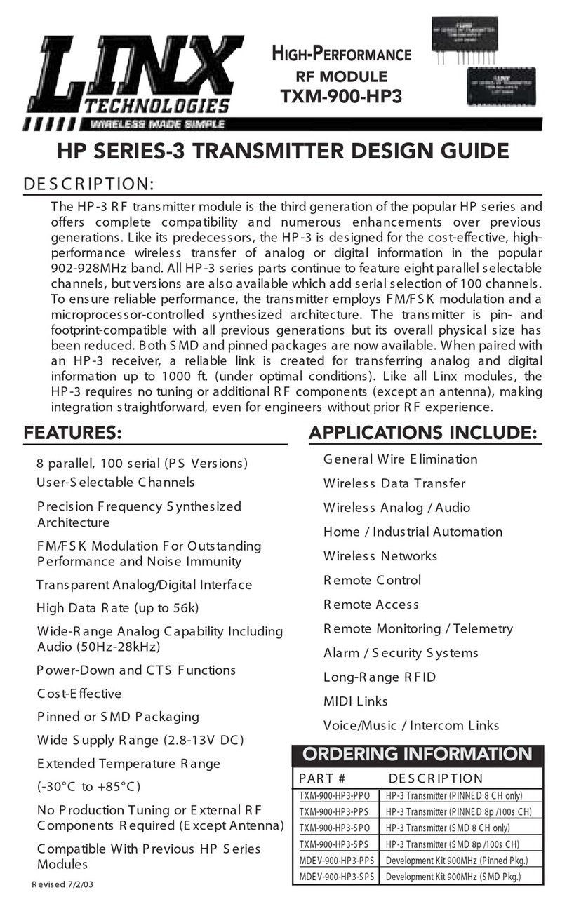
Linx HP-3 series Guide

Linx

Linx HP-3 series Guide

Linx SI Keyfob Instruction Manual

Linx

Linx SI Keyfob Instruction Manual

Linx DS Series Instruction Manual

Linx

Linx DS Series Instruction Manual

Linx TXE-315-KH User manual

Linx

Linx TXE-315-KH User manual

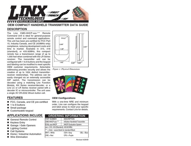
Linx CMD-HHCP series Instruction Manual

Linx

Linx CMD-HHCP series Instruction Manual

Linx OTX HH KF MS Series Instruction Manual

Linx

Linx OTX HH KF MS Series Instruction Manual

Linx MS Compact User manual

Linx

Linx MS Compact User manual

Linx HT Keyfob Instruction Manual

Linx

Linx HT Keyfob Instruction Manual

Linx MDEV-315-HH-LR8-HS User manual

Linx

Linx MDEV-315-HH-LR8-HS User manual

Popular Transmitter manuals by other brands

enika P8 T 2 IP quick start guide

enika

enika P8 T 2 IP quick start guide

Nyrius NY-GS10 manual

Nyrius

Nyrius NY-GS10 manual

evertz 2408RGBT/DVIT instruction manual

evertz

evertz 2408RGBT/DVIT instruction manual

Audio Resource Group ARG-TX90MST manual

Audio Resource Group

Audio Resource Group ARG-TX90MST manual

Endress+Hauser RMA42 operating instructions

Endress+Hauser

Endress+Hauser RMA42 operating instructions

THOMSON IOX Series Maintenance manual

THOMSON

THOMSON IOX Series Maintenance manual

Me BELL-501 TX instruction manual

Me

Me BELL-501 TX instruction manual

ASCON TECNOLOGIC S.r.l. ZTT-61/GD user guide

ASCON TECNOLOGIC S.r.l.

ASCON TECNOLOGIC S.r.l. ZTT-61/GD user guide

Extron electronics DTP T EU 232 user guide

Extron electronics

Extron electronics DTP T EU 232 user guide

Vaisala HUMICAP HMT120 Series user guide

Vaisala

Vaisala HUMICAP HMT120 Series user guide

scope Connexions CX4 Installation & user manual

scope

scope Connexions CX4 Installation & user manual

SenseAir aSENSE installation manual

SenseAir

SenseAir aSENSE installation manual

halstrup-walcher P26 instruction manual

halstrup-walcher

halstrup-walcher P26 instruction manual

Mantracourt T24-ACM series user manual

Mantracourt

Mantracourt T24-ACM series user manual

RKI Instruments 65-2643-05SS-4S Operator's manual

RKI Instruments

RKI Instruments 65-2643-05SS-4S Operator's manual

Emerson Fisher 4200 Series instruction manual

Emerson

Emerson Fisher 4200 Series instruction manual

Michell Instruments Easidew PRO I.S. user manual

Michell Instruments

Michell Instruments Easidew PRO I.S. user manual

M-system Mini-M M2XUM instruction manual

M-system

M-system Mini-M M2XUM instruction manual

manuals.online logo
manuals.online logoBrands
  • About & Mission
  • Contact us
  • Privacy Policy
  • Terms and Conditions

Copyright 2025 Manuals.Online. All Rights Reserved.