Lion Precision SPINDLECHECK User manual

www.lionprecision.com/two-year-warranty/ Document No. M017-7500.004
2Oakdale, MN, USA www.lionprecision.com 651-484-6544
This instruction manual details the operation of the Lion
Precision’s SpindleCheck Machine Capability Tester
system with SpindleCheck Inspector Software. Please
contact us if you have any questions or suggestions on
how we can be of greater service to you.
Lion Precision
651-484-6544
www.spindlecheck.com
www.lionprecision.com
Manual Version:M017-7500.004

www.lionprecision.com/two-year-warranty/ Document No. M017-7500.004
3Oakdale, MN, USA www.lionprecision.com 651-484-6544
TABLE OF CONTENTS
INTRODUCTION 5
Measurements Performed by SpindleCheck 5
SpindleCheck Components 6
COMPONENT 1 - SPINDLECHECK DEVICE ELECTRONICS 7
Probe Connections 7
Index Sensor (Purple) 8
Capacitive Displacement Sensors (X, Y, Z) 8
COMPONENT 2 - CAPACITIVE PROBES (X, Y, Z) 9
COMPONENT 3 - EDDY CURRENT PROBE (INDEX) 9
COMPONENT 4 - PROBE SPACER 9
COMPONENT 5 - PROBE NEST AND MAGNETIC BASE 9
COMPONENT 6 - PRECISION TARGET PIN 10
COMPONENT 7 - “ROUND” ADAPTER 10
COMPONENT 8 - “ROUND WITH FLATS” ADAPTER 10
COMPONENT 9 - FLASH DRIVE WITH SOFTWARE 10
COMPONENT 10 - BATTERY & CHARGER 11
COMPONENT 11 - GROUND BRUSH 11
COMPONENT 12 - GROUNDING KIT 11
SOFTWARE INSTALLATION 12
Minimum Requirements 12
Installation Procedure 12
SOFTWARE BASICS 13
Operating Mode 13
Machine Selection 13
Status Bar 13
READING MEASUREMENT SCREENS 14
Axis Names 14
Initial Display 14
Overall Results Area 14
Chart Area Time/Sample/RPM 15
Displayed Data 15
Compare Data 15
PREPARING TO MAKE MEASUREMENTS 16
Power the SpindleCheck device 16
Connect Device to Computer 16
Launch SpindleCheck Inspector 17

www.lionprecision.com/two-year-warranty/ Document No. M017-7500.004
4Oakdale, MN, USA www.lionprecision.com 651-484-6544
Conrm Settings 18
Settings > Wireless 20
Select a Machine (Machine Manager) 21
Install the Target Pin 24
Target Pins Care and Safety 24
Install and Position Probes 24
Measurement Types 27
MAKING MEASUREMENTS 27
Warm-Up 28
POSITIONING CAPABILITY 28
Vibration 29
Repeatability 31
Thermal 32
Setup/Run 33
CUTTING CAPABILITY 33
Total Error 35
Runout 36
Roundness 38
Roughness 39
MEASUREMENT SEQUENCES 40
Measure Machine Sequence 40
Crash Test Sequence 40
VIEWING REPORTS 41
Printing and Viewing Options 41
Machine: Machine Capability 41
Machine: Machine Trends 41
Shop Reports 41
Appendix A: Replacement Parts 42
GLOSSARY 43
APPROVALS AND SAFETY CONSIDERATIONS 46
Wireless System 46
Battery 48
Material Requirements 49
Target Pins Care and Safety 49
SOFTWARE LICENSE AGREEMENT 50
Standards and References 50
Assistance 50

www.lionprecision.com/two-year-warranty/ Document No. M017-7500.004
5Oakdale, MN, USA www.lionprecision.com 651-484-6544
INTRODUCTION
The SpindleCheck device is a precision measurement system for measuring the dynamic
performance of machine tools and their spindles.
SpindleCheck Inspector is a software package which retrieves and interprets the measurements
from the SpindleCheck device and presents the results to the operator. The results inform the
user about the capabilities of the machine.
Fundamental Concepts
SpindleCheck uses noncontact, capacitive sensors to measure error motions as changes in
position of a precision target pin installed in the machine spindle.
The measurements are collected and analyzed by the SpindleCheck Inspector software.
Measurement results are presented on-screen as changes over time or over dierent RPMs.
Overall values are calculated and presented for the machine as a whole and for each axis.
Measurements Performed by SpindleCheck
SpindleCheck Inspector performs the following measurements as described in ISO, ANSI/ASME,
and JIS standards:
SpindleCheck
Inspector
Measurement
International Standards
Description
Spindle Operation
During Test
Thermal Rotating or non-rotating
spindle Rotating/Not Rotating
Repeatability Repeatability Not Rotating
Vibration Vibration Not Rotation
Warm-Up Thermal Drift Rotating
Total Rotational Error Total Error Rotating
Runout Total Indicator Reading (TIR) Rotating
Position Shift Position Shift Rotating
Roundness Synchronous Error Rotating
Surface Roughness Asynchronous Error Rotating

www.lionprecision.com/two-year-warranty/ Document No. M017-7500.004
7Oakdale, MN, USA www.lionprecision.com 651-484-6544
COMPONENT 1 - SPINDLECHECK DEVICE ELECTRONICS
The sensor system electronics include driver electronics for the capacitive and index probes, an
internal wireless router, a USB port for communicating with the PC, a battery slot, power and
ground connections, a power switch, and probe position indicators useful during setup.
The rear of the device has four rubber feet and is magnetic for securing to a clean surface inside
the machine.
Probe Connections
The Index sensor channel and X, Y, and Z capacitive displacement sensor channels are color
coded. The colored blocks of each channel must match the color-coded rings on each probe.
Calibration stickers for each capacitive sensor channel (X, Y, and Z) are located on the back of
the device. These indicate probe serial numbers and their association with particular channels.

www.lionprecision.com/two-year-warranty/ Document No. M017-7500.004
8Oakdale, MN, USA www.lionprecision.com 651-484-6544
Index Sensor (Purple)
An index pulse is used to detect rotation. This signal is also used to align
readings from multiple revolutions. The Index sensor uses an eddy current
probe to detect the copper plating on the target pin.
The indicator lights provide feedback regarding the index function.
Signal Strength
The Index probe senses a dierence between the copper and steel on the
target. When the spindle is rotating, the resulting signal from the probe is
used to time the measurements of the rotating spindle. The probe signal
must be suciently large to ensure reliable triggers to the system. The closer
the probe is to the target, the greater the signal strength, but the probe must
maintain a safe distance from the rotating target to avoid contact. The PROBE
SPACER is provided to set the ideal gap.
Signal Strength Indicator Conditions:
• Green: Good signal strength
• Red: Poor signal strength or no rotation
Capacitive Displacement Sensors (X, Y, Z)
The X, Y, and Z Axes each have a separate color-coded capacitive
displacement sensor channel. The colored blocks of each channel must match
the color-coded rings on each probe.
X: Blue
Y: Green
Z: Red
Indicator lights are Green when the probe is within its calibrated range.
The Near or Far light will be Red when the probe is outside of its calibrated
range.
The Near and Far lights will be Blue when the capacitive probe is not
connected.
INDEX
This indicator lights Green when the Index probe is reading the copper strip and is O when the
Index probe is over the steel.
WAIT
The wait indicator lights during the 60-90 second initialization period when power is rst applied
to the SpindleCheck device. No communication between the computer and device is possible
during this time.

www.lionprecision.com/two-year-warranty/ Document No. M017-7500.004
9Oakdale, MN, USA www.lionprecision.com 651-484-6544
COMPONENT 2 - CAPACITIVE PROBES (X, Y, Z)
COMPONENT 3 - EDDY CURRENT PROBE (INDEX)
COMPONENT 4 - PROBE SPACER
COMPONENT 5 - PROBE NEST AND MAGNETIC BASE
Noncontact capacitive probes measure the distance to the
precision target pin as it turns. The probes are 8 mm in
diameter, have a total measurment range of 0.250 mm
(0.01 inch), and a minimum gap (Near Gap) of 0.125 mm
(0.005 inch).
Calibration labels on the back of the electronics housing
will list the specics of the calibrations. If capacitive probes
are damaged, the probe and the driver electronics for that
channel must be replaced together to maintain accuracy.
Part Number P016-6002.
The eddy-current Index probe provides a once-around
signal to align data for multiple rotations. Its nominal
distance from the target is 0.25 mm (0.01 inch). Use
cautionly to prevent damage.
Part Number P017-7070.
The Probe Spacer is 0.25 mm (0.01 inch) thick and is used
to set the gap between the probes and the target pin.
Part Number A017-7560.
The probe nest includes mounting for X, Y, Z probes and an Index probe.
Part Number P017-6207.

www.lionprecision.com/two-year-warranty/ Document No. M017-7500.004
10Oakdale, MN, USA www.lionprecision.com 651-484-6544
COMPONENT 6 - PRECISION TARGET PIN
A precision ground 8 mm pin is used as a target for measurements. The pin has a precision 1
inch (25.4 mm) diameter spherical end for Z-Axis measurements and a precision surface for
measurements in the X and Y directions. The pin includes a collar with a copper plated area
which is sensed by the Index probe.
The precision surfaces are important for accurate measurements. If these surfaces are
damaged, the pin should be renished by Lion Precision to restore an accurate reference
surface.
Part Numbers: 8mm pin – MFG5-1240 & 20mm pin – MFG5-1241.
Index
X, Y, Z
Probes Measurement
Target
COMPONENT 7 - “ROUND” ADAPTER
COMPONENT 8 - “ROUND WITH FLATS” ADAPTER
COMPONENT 9 - FLASH DRIVE WITH SOFTWARE
The Round Adapter mounts the probe nest to a cylindrical
shank which can be mounted in the lathe turret. To use the
adapter, remove the three screws holding the probe nest
to the magnetic base. Remove the three screws holding
the magnetic base adapter plate to the probe nest – use
the same three screws to mount the probe nest to the
adapter plate on the adapter.
Part Numbers: 1”- B017-3901 ; 1.25” – B017-3902 ;
20mm – B017-3905 ; 25mm – B017-3906 ; 3/4” B017-
3900.
The Round with Flats Adapter mounts the probe nest to a
shank with two ats which can be mounted in the live
tooling mount. To use the adapter, remove the three
screws holding the probe nest to the magnetic base.
Remove the three screws holding the magnetic base
adapter plate to the probe nest – use the same three
screws to mount the probe nest to the adapter plate on
the adapter.
Part Numbers: 1” – B017-3911; 1.25” B017-3912;
3/4” – B017-3910.
The 8G ash drive contains the SpindleCheck Inspector
software. See software on page 12 for installation details.

www.lionprecision.com/two-year-warranty/ Document No. M017-7500.004
11Oakdale, MN, USA www.lionprecision.com 651-484-6544
COMPONENT 10 - BATTERY & CHARGER
COMPONENT 11 - GROUND BRUSH
COMPONENT 12 - GROUNDING KIT
The 15VDC battery is a lithium-ion type. Two are provided
with each system. The battery housing is polarized and will
only insert in the SpindleCheck device one way. The
battery lasts about four hours and requires about ve
hours to fully charge.
System also comes with a battery charger.
Part Number P017-7570 and 2901-0060 (Charger)
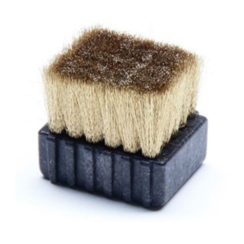
The Ground Brush can be fastened into the probe nest and
the carbon ber brush used to ground the target pin while
spinning. This is usually not necessary but can be helpful
in an electrically noisy environment. If readings are erratic
or the Roughness measurement unusually high, the
ground brush may be necessary.
Part Number P017-4351.
Grounding the SpindleCheck device to the spindle housing may be necessary to reduce electrical
noise from the machine’s environment. The ground strap
includes a “banana” plug to connect to the SpindleCheck ground connector and a clamp to
connect to a convenient point on the spindle housing.
Part Number P014-8250.

www.lionprecision.com/two-year-warranty/ Document No. M017-7500.004
12Oakdale, MN, USA www.lionprecision.com 651-484-6544
SOFTWARE INSTALLATION
Minimum Requirements
Note .NET3.5 must be installed before running SpindleCheck Inspector installation.
Windows 8 or higher (64 bit)
8G memory
64G free disk space
1 GHz Processor
1 Available USB port (2.0 or higher); 1024 x 768 Minimum Screen Resolution
Installation Procedure
The SpindleCheck Inspector program is installed in the \Program Files (x86)\Lion
Precision\Spindle Check Inspector directory on your hard disk. If you install the SpindleCheck
Inspector software a second time using the same subdirectory, the previous installation will
automatically be uninstalled rst.
To use the SpindleCheck Inspector ash drive:
1. Ensure you have a good internet connection.
2. Insert the Lion Precision SpindleCheck Inspector ash drive in available USB port.
3. View the contents of the ash drive.
4. Run SpindleCheckInspectorInstall.exe
5. Follow the directions of the installation programs.
6. When the installation is done, restart the computer.
7. After restarting, run the program by selecting the icon on the desktop, or by selecting Start
> All Programs > SpindleCheck Inspector > SpindleCheck Inspector.exe

www.lionprecision.com/two-year-warranty/ Document No. M017-7500.004
13Oakdale, MN, USA www.lionprecision.com 651-484-6544
SOFTWARE BASICS
Operating Mode
When the SpindleCheck Inspector is launched (Start > SpindleCheck Inspector) it will try to
connect to a SpindleCheck device. If it is successful, the Home Screen will be displayed.
If it does not nd a connection to a SpindleCheck device, you will be given the option to Retry
the connection, or to View Data previously collected.
More details in the Launch SpindleCheck Inspector section.
Machine Selection
To make measurements, SpindleCheck Inspector requires a SpindleCheck device to be
connected and a machine to be loaded from the database. When a device is not connected
and/or a machine is not loaded, Home Screen measurement buttons will be deactivated (grayed
out).
More details in Select a Machine (Machine Manager).
Status Bar
The Status Bar at the bottom of the screen displays the following information:
• SpindleCheck Inspector software version
• Connection to device status:
▪ Device Connected
• Rotation status:
▪ Spinning
• Current RPM
• Constant Error/Unstable
• Currently selected pin size. Accurate measurements require the correct pin size be selected.

www.lionprecision.com/two-year-warranty/ Document No. M017-7500.004
14Oakdale, MN, USA www.lionprecision.com 651-484-6544
READING MEASUREMENT SCREENS
Axis Names
Some measurements read each axis separately (Warm-Up, Vibration, Repeatability, Thermal,
Runout, Position Shift) and report results for the X, Y, and Z axes. Other measurements read the
“radial” axis as a mathematical combination of X and Y (Total Error, Roundness, Roughness) and
report results for the Radial and Axial axes.
Initial Display
When a measurement screen is rst displayed it will show the most recent results of that
measurement for the current machine. At the conclusion of a new test run, the screen will
display the just completed test results.
Overall Results Area
Values
The Overall Results Area contains measurement values intended to give an overall picture of the
machine and each axis. “Axis Averages” indicate the condition of individual axes. The
“Combined” value represents the machine overall. The Combined value is always larger than the
values for individual axes.

www.lionprecision.com/two-year-warranty/ Document No. M017-7500.004
15Oakdale, MN, USA www.lionprecision.com 651-484-6544
Pass/Fail
If Pass/Fail numbers are entered into the Machine Manager > Pass/Fail, the Combined result will
be compared to the Pass/Fail number. If no number has been entered in the Pass/Fail screen, a
Pass/Fail test will not be performed.
Best/Worst RPM
For measurements taken across a range of spindle speeds, this area lists the best and worst
performing speeds for each axis.
Notes
Notes regarding the currently displayed measurement can be entered or edited at any time.
Clicking in the Notes text box will allow you to type or edit with the usual Windows text
functions. Use the “Save” button to save your notes.
Chart Area Time/Sample/RPM
The chart area of each screen displays a table of the measurements at each test condition (RPM,
Time, or Sample). Moving the cursor over the chart will display the individual values at each
point on the table.
Displayed Data
The Screen displays the most recent measurement results for the current machine. To view an
earlier measurement of the machine, use the “Displayed Data” drop down to select a dierent
Date/Time/Type record to display. The Chart Area and Overall Results Area will display the
selected record.
Compare Data
In the Chart Area, you can also compare two dierent sets of measurements for the same
machine. Select another Date/Time/Type record from the Compare Data dropdown. The chart
will simultaneously display the Compare Data with dashed lines. The Overall Results Section will
continue to display the Displayed Data information.
The Notes section can be selected to show Display data or Compare data with the buttons under
the Notes textbox.

www.lionprecision.com/two-year-warranty/ Document No. M017-7500.004
16Oakdale, MN, USA www.lionprecision.com 651-484-6544
PREPARING TO MAKE MEASUREMENTS
The process of making measurements follows this basic sequence:
1. Power the SpindleCheck device
2. Connect the device to the computer
3. Launch SpindleCheck Inspector software
4. Conrm settings
5. Load or create the machine to be measured from the machine database
6. Install the target pin in the spindle
7. Install and position the measurement probes
Power the SpindleCheck device
Insert a battery into the SpindleCheck (or connect to power supply) and turn the power switch
on. The NOT READY light will be on (Index channel) for about 90 seconds. During this time, no
communication is possible with the device.
Connect Device to Computer
Option A – Connect through WiFi Network
1. Select the Network icon in the notication area on your computer.
2. In the list of networks, choose “SpindleCheck” to connect to, and then select Connect. We
recommended you to check the “Connect Automatically”.
3. Type the security key (often called the password), “LionPrecision” and then click Next. Why
isn’t this called a “password”?

www.lionprecision.com/two-year-warranty/ Document No. M017-7500.004
17Oakdale, MN, USA www.lionprecision.com 651-484-6544
4. >… Select “Home network” and it might need a few minutes to setup.
5. When the WiFi is successfully connected, the Network or icon will show like this .
Change wireless SSID and Password please refer to Settings > Wireless
Launch SpindleCheck Inspector
When the SpindleCheck Inspector is launched (Start > SpindleCheck Inspector ) it will try to
connect to a SpindleCheck device. If it is successful, the Home Screen will be displayed. If it
does not nd a connection to a SpindleCheck device, you will be given the option to Retry the
connection, or to View Data previously collected.
“Retry”
1. Conrm the SpindleCheck device is turned on and its Not Ready light is o.
2. Conrm that the computer is connected to the SpindleCheck wireless network or connected
by USB cable.
3. Then Retry.
Home Screen
The Home Screen of SpindleCheck Inspector contains eight buttons to access dierent functions.
When rst launched, some of the buttons will be grayed out as they have no function until a
particular machine is specied. When a machine has been loaded, the machine description will
be listed in the top right corner next to the Lion Precision logo. If you are going to measure a
machine, the rst step is loading a machine in the Machine Manager.
Option B – Connect through USB
1. Plug in the USB cable – TypeB to SpindleCheck Inspector and
the other end USB – TypeA to the host computer.
2. This might take a few minutes for the computer to recognize
and install the driver.
3. Check to see if a device name called “Microsoft Windows
Mobile Remote Adapter #xx” or “CompactFlex” is active.

www.lionprecision.com/two-year-warranty/ Document No. M017-7500.004
18Oakdale, MN, USA www.lionprecision.com 651-484-6544
Conrm Settings
Settings > Conguration
Units
Choose inch or mm for display. The units can be changed anytime.
Target Pin
The noncontact sensors measure changes in distance between the sensor and the Target Pin
placed in the axis of rotation of the machine. The Target Pins are designed with a precise
diameter and minimal roundness error.
The SpindleCheck system must know the size of the Target Pin to make precise calculations
during measurements. Be certain to select the correct pin size you are using during your
measurement.
Target Pin Serial
This is an optional entry.
Target Pins are marked with serial numbers. The Target Pin serial number is recorded with each
measurement to support traceability.

www.lionprecision.com/two-year-warranty/ Document No. M017-7500.004
19Oakdale, MN, USA www.lionprecision.com 651-484-6544
Language
Select your desired language and a message box will popup to conrm the action. After clicking
“Yes” the program will shut down, and the user will need to restart the program, if clicking “No”,
the language eld changes back to previous language, no restart is necessary.
Calibration
The Calibration section lists the specic probe and electronic component serial numbers, and
Near gap and Far gap for each measurement channel. It also lists the date of the last calibration
of the system.
IF A PROBE IS VISIBLY DAMAGED, accuracy will be aected. The probe and its driver
electronics should be replaced.
Settings > System Data
WARNING

www.lionprecision.com/two-year-warranty/ Document No. M017-7500.004
20Oakdale, MN, USA www.lionprecision.com 651-484-6544
Diagnostics
The Diagnostics section lists data relative to the inner workings of the software and the
electronics. These values may be needed by Lion Precision engineers to troubleshoot the system
in the unlikely event that there is a problem.
Settings > Wireless
This Wireless Panel is for the user to change/update the wireless network name (SSID) and
Wireless Password.
• Make sure device is connected through WiFi network.
• Current Password – Will show you the previous changed password by using this PC.
• All text boxes must be entered. If one of them is empty, software will prompt warning.
• There is a “Show Password” Checkbox. User can check it and both Password and Conrm
Password textbox will show the password.
• SSID - Desire name for the wireless broadcast.
• Click the Update button and the software will update the router with the new password and
SSID on the router.
• A message box will prompt when the router is successfully updated. The user will be dropped
o from the current connection and require reconnecting with the updated network
password.
Password and Conrm Password - Must be longer than 8 characters and both inputs
must match or else the software will prompt warning.
WARNING
Table of contents


