Lipper Power Bimini User manual

Tracker Marine
Power Bimini
OEM INSTALLATION MANUAL

Rev: 01.20.22 Page 2 CCD-0004551
TABLE OF CONTENTS
Introduction 2
Safety 2
Resources Required 3
Preparation 4
Actuator Mounting Locations 4
Installation 4
With Touch Controller 4
Without Touch Controller 7
Operation 8
With Touch Controller 8
Without Touch Controller 23
Troubleshooting 24
Notes 25
Introduction
The SureShade Power Bimini is an electric actuator-driven Bimini top powered by a 12V DC source, that can
be controlled by a two-button Touch Controller or with a Bluetooth® compatible app.
For information on the assembly or individual components of this product, please visit:
https://support.lci1.com/marine-products/ .
Note: Images used in this document are for reference only when assembling, installing and/or operating
this product. Actual appearance of provided and/or purchased parts and assemblies may differ.
Safety
Read and understand all instructions before installing or operating this product. Adhere to all safety labels.
This manual provides general instructions. Many variables can change the circumstances of the instructions,
i.e., the degree of difficulty, operation and ability of the individual performing the instructions. This
manual cannot begin to plot out instructions for every possibility, but provides the general instructions,
as necessary, for effectively interfacing with the device, product or system. Failure to correctly follow the
provided instructions may result in death, serious personal injury, severe product and/or property damage,
including voiding of the LCI limited warranty.

Rev: 01.20.22 Page 3 CCD-0004551
The "WARNING" symbol above is a sign that a procedure has a safety risk involved and may cause
death or serious personal injury and/or severe product or property damage if not performed safely
and within the parameters set forth in this manual.
Failure to follow instructions provided in this manual may result in death, serious personal injury
and/or severe product and property damage, including voiding of the component warranty.
The “CAUTION” symbol above is a sign that a safety risk is involved and may cause personal injury
and/or product or property damage if not safely adhered to and within the parameters set forth
in this manual.
Always wear eye protection when performing service, maintenance or installation procedures.
Other safety equipment to consider would be hearing protection, gloves and possibly a full face
shield, depending on the nature of the task.
All electrical wiring harnesses shall be loomed and secured to prevent possible damage and
installed in accordance with the latest ABYC (American Boat and Yacht Council) electrical standards,
E11 and S31
Only open the bimini top indoors when testing for proper installation. Opening the bimini top
outdoors subjects the system to possible strong winds that could result in severe product damage.
Only open the bimini top indoors when testing product for proper operation.
Do NOT fully open the bimini frame without the canvas top installed when testing product for
proper operation. Opening the bimini frame without the canvas top installed will result in severe
product damage. Only fully open the bimini frame with the canvas top installed.
Resources Required
• 1-2 persons, depending on task
• Pencil
• Cordless or electric drill or screw gun
• 3/8" drill bit
• Appropriate drive bits
• Tape measure
• 9/16" wrench
• Screwdriver
Rev: 01.20.22 Page 4 CCD-0004551
Installation
With Touch Controller
1. Place the quick-connect (QC) power bimini system onto the boat's frame/railing.
Note: Proper rear strut assembly positioning is generally determined by locating the assembly so that
when the top is down, the struts are just behind the rear seats. Too far forward and the top will
interfere with rear seating; while too far rearward will provide less shade to the front of the boat.
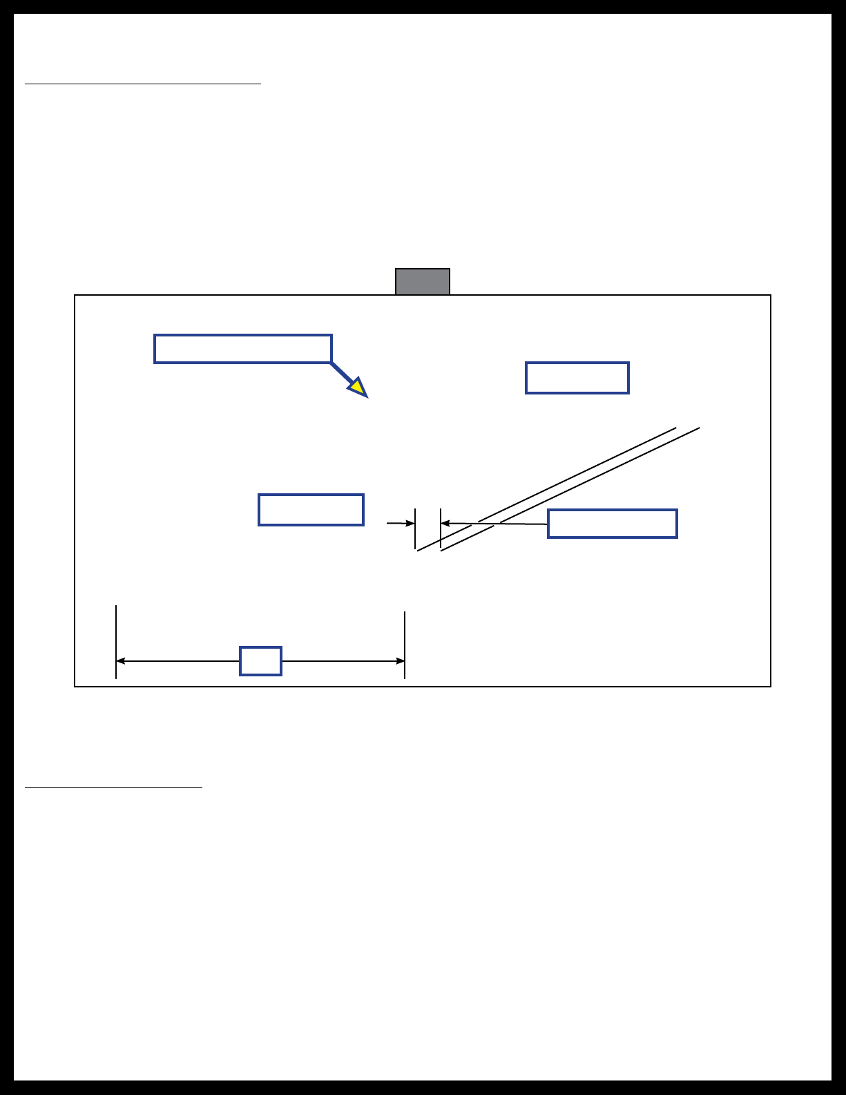
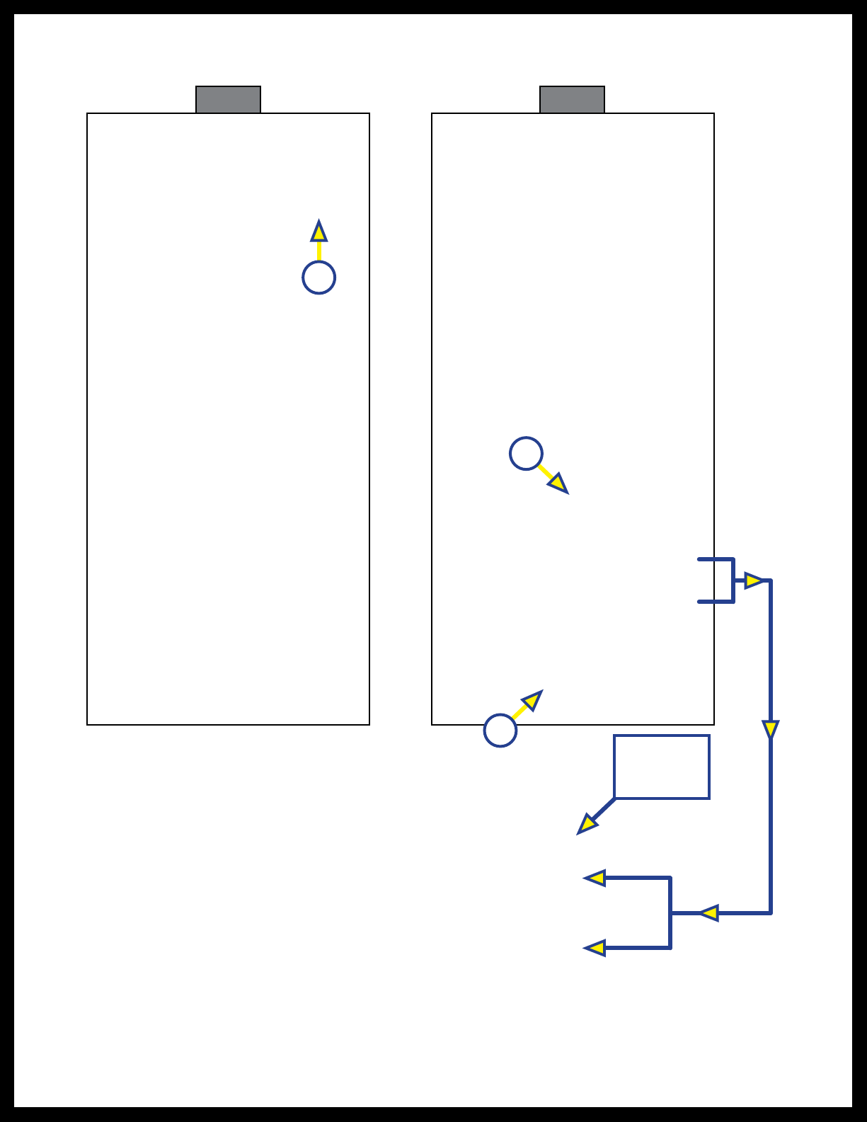
2. Move the LH and RH actuator assemblies (Fig. 1) forward and backward until the actuators are in-line
with each other.
A. Make sure the actuators are mounted square, level and plumb to one another.
B. Make sure no actuator is mounted more than 1/4" ahead of the other (Fig. 1).
Preparation
Actuator Mounting Locations
When installing the complete power bimini system onto the boat's railing, make sure:
• The actuators are mounted square, level and plumb to one another (Fig. 1).
• No actuator is mounted more than 1/4" ahead of the other (Fig. 1).
• Wires are run in a manner that will prevent them from being pinched under the actuators.
• Actuator minimum voltage is 11V DC when under load.
While facing the front (bow) of the boat, there is a right-handed (RH)—starboard—and a left-handed (LH)—
port—actuator. The RH actuator has a two-wire harness exiting beneath the controller for connecting to the
boat's electrical power. Both actuators are pre-wired through the rear frame assembly.
Fig. 1
16"
1/4" Max Offset
Align Actuators Even
RH Actuator
LH Actuator

Rev: 01.20.22 Page 5 CCD-0004551
Some boat frames/railings may be pre-wired. Drilling through a pre-wired frame/railing may nick
or cut electrical wires, resulting in a damaged and/or unusable electrical harness. Carefully drill
through one surface and inspect for wiring.
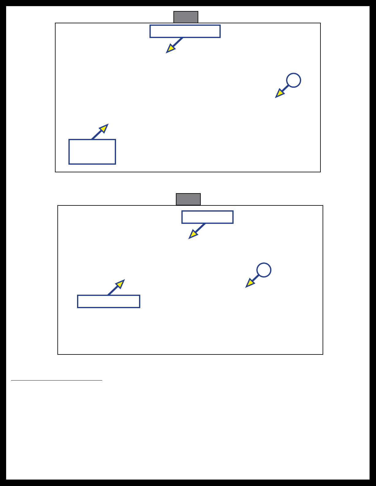
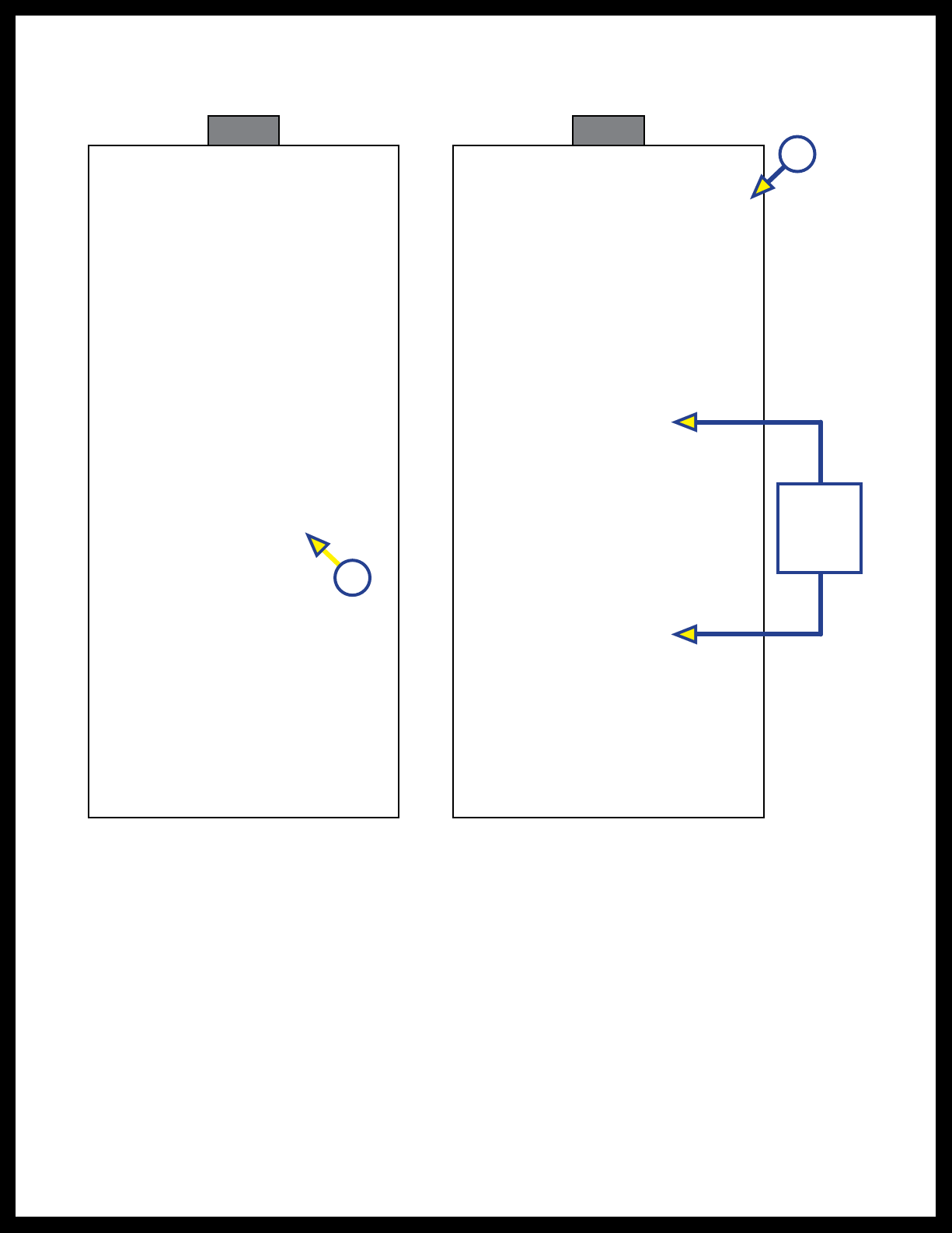
3. After properly positioning each strut/actuator assembly, use a pencil to mark the center locations of
each actuator's mounting studs (Fig. 2A).
1/2" Ref.
16 1/2"
Front of
Actuator
Center of Frame/
Railing Width
A
A
Fig. 2
4. Remove the QC power bimini system from the boat and set aside.
5. Make sure the center marking for each mounting stud is centered across the width of the frame/railing
and measures 16" apart (Fig. 1) on center.
6. Make sure each set of markings are aligned to one another, left-to-right.
7. At each pencil mark, drill a through-hole using a 3/8" drill bit. These holes need to go all of the way
through the railing tube.
Note: Use care when drilling through a pre-wired boat frame/railing. If necessary, drill through one wall of
the tube, then inspect for wires to make sure they are out of the way.
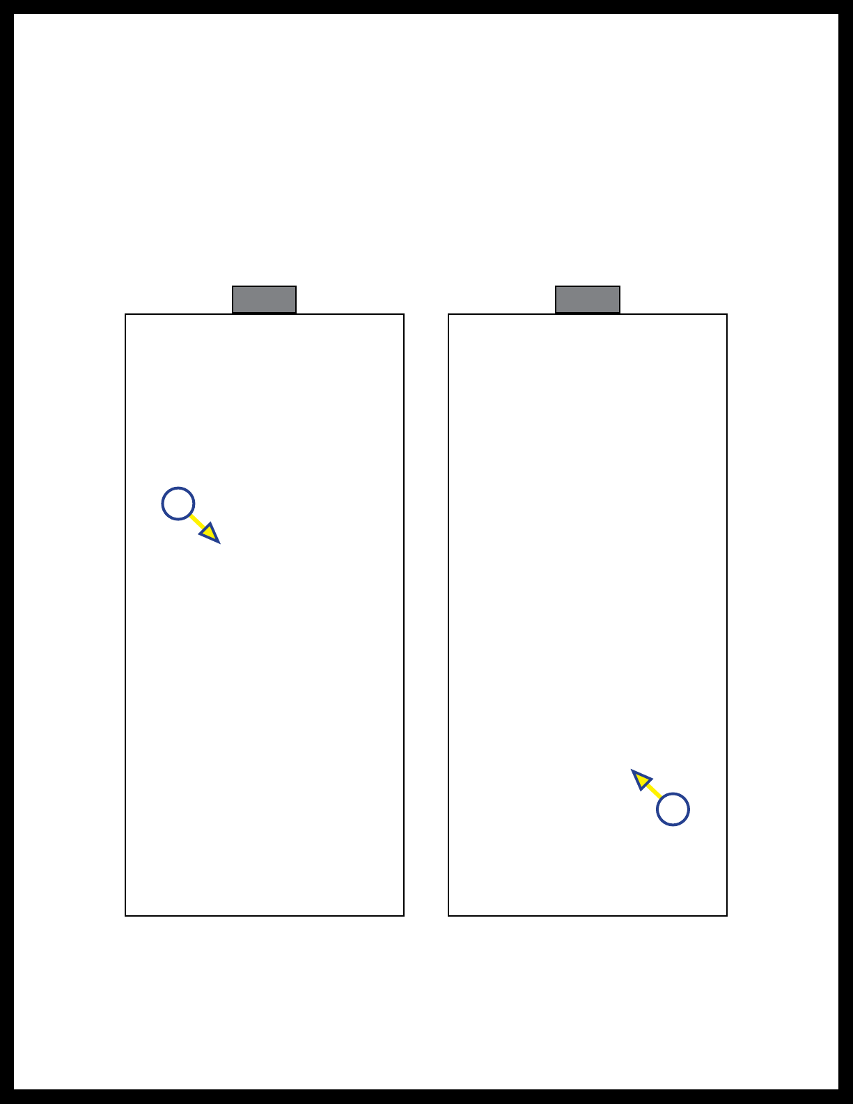
8. Place the previously removed (step 4) QC power bimini system on top of the frame/railing so that the
actuators' mounting studs align with the drilled holes in the frame/railing.
9. Connect the actuator's wire harness to the boat's power source:
Note: Use care to make sure wires are not pinched underneath the actuators.
A. Use wire harness channels on the underside of the actuators to avoid pinching wires.
B. If necessary, drill an access hole into the RH frame/railing for the two-wire power harness
connectors to pass through.
10. Make sure each stand-off leg rests as near the center-width of the boat's frame/railing as possible.

Rev: 01.20.22 Page 6 CCD-0004551
Fig. 3
11. Secure complete QC bimini system in place with 5/16" split lock washers and 5/16"-18 acorn nuts
(Fig.3A) four places.
12. Use a 9/16" wrench to tighten the acorn nuts.
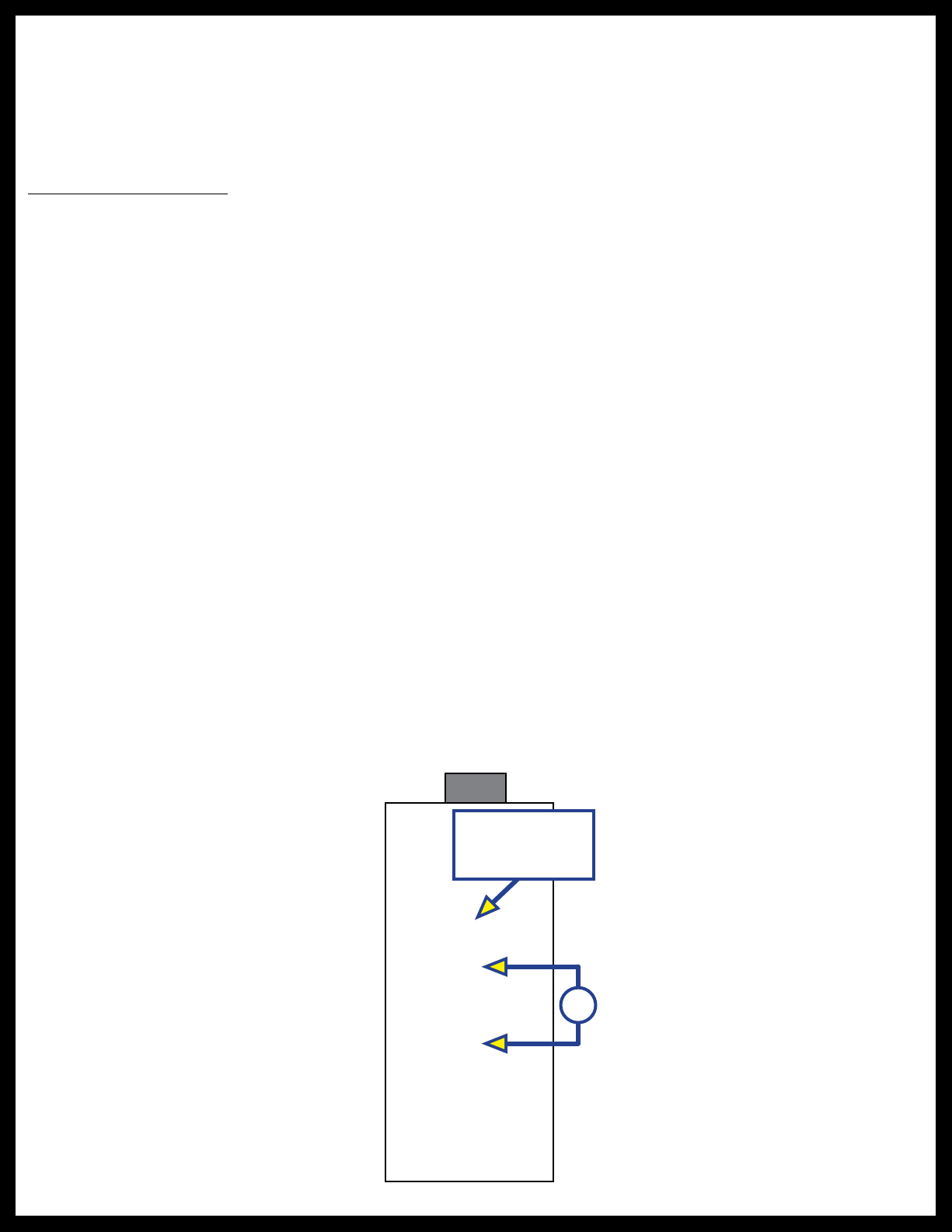
Touch Controller and Nose Mount Cap
The Lippert Quick Connect (QC) Touch Controller is pre-wired to the system frame harnesses.
The Touch Controller and Nose Mount Cap are part of the complete system frame, but requires attachment
to the boat's railings.
Attach the QC Touch Controller as follows:
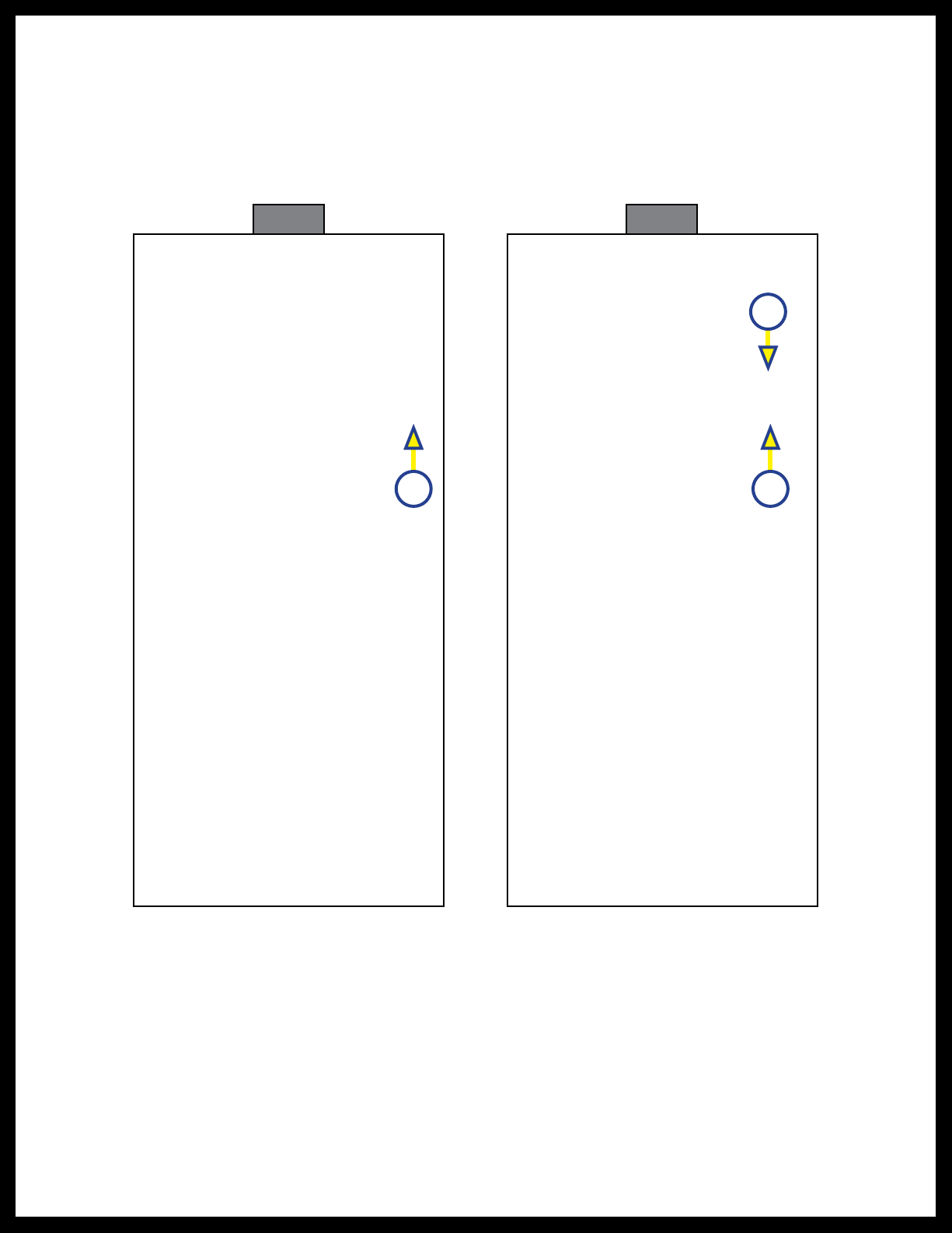
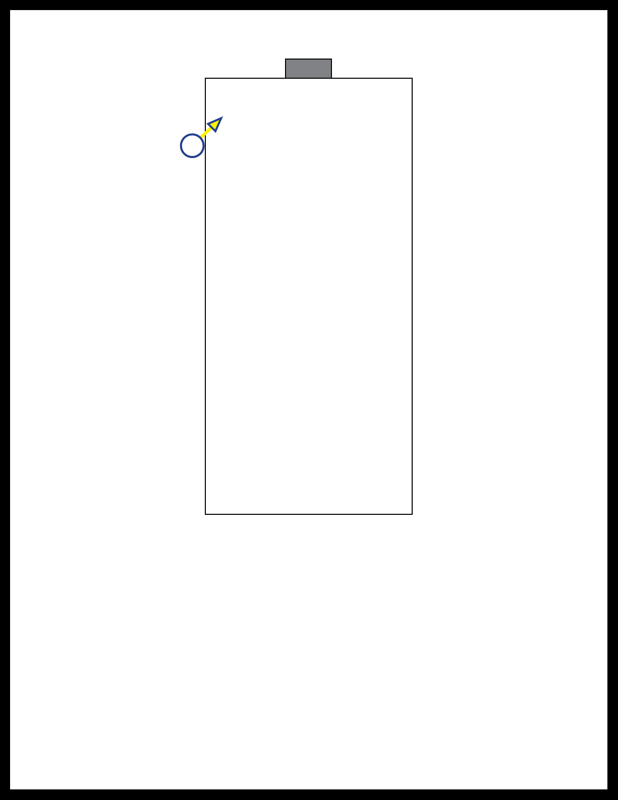
1. Remove the protective cap over the Touch Controller's mounting screw (Fig. 4A).
2. Carefully tuck excess controller and actuator wires into the open end of the actuator.
3. Install the Touch Controller into the end of the actuator while aligning the controller's base with the
top of the boat railing (Fig. 4).
4. Fasten the front of the controller to the boat railing with the provided screw.
5. Reinstall the previously removed (step 1) protective cap over the mounting screw.
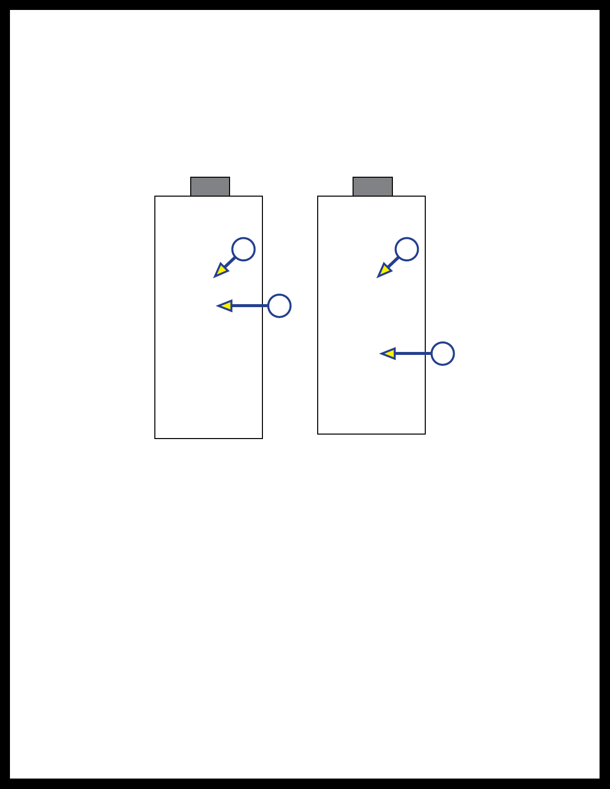
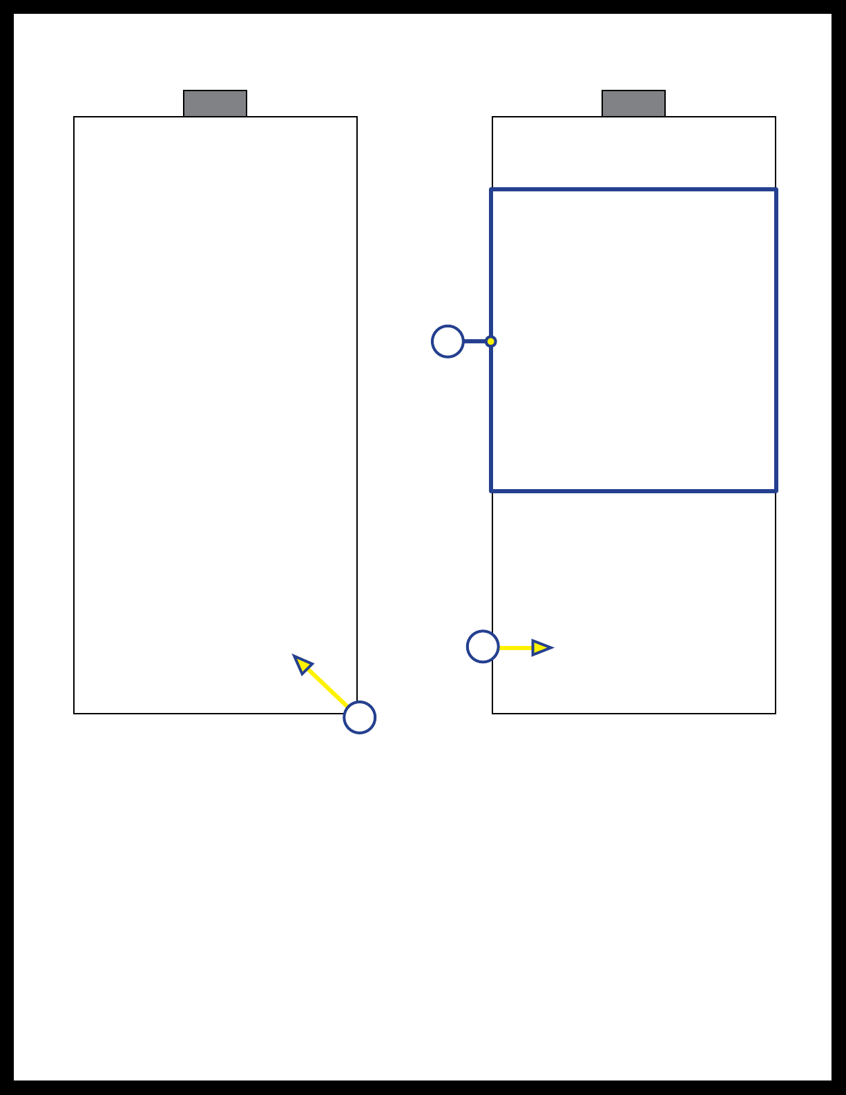
6. Remove the protective cap over the Nose Mount Cap mounting screw (Fig. 5A).
7. Carefully tuck excess actuator wires into the open end of the actuator.
8. Install the Nose Mount Cap into the end of the actuator while aligning the cap's base with the top of
the boat railing (Fig. 5).
9. Fasten the front of the Nose Mount Cap to the boat railing with the provided screw.
10. Reinstall the previously removed (step 6) protective cap over the mounting screw.
A
AA
A
Actuator
Mounting
Stud
Lock
Washer
Acorn
Nut
Rev: 01.20.22 Page 7 CCD-0004551
Fig. 4
A
Starboard
Boat Railing
Starboard Actuator
Note: Actuator wire harness not shown for clarity.
Fig. 5
Port Actuator
A
Port Boat Railing
Note: Actuator wire harness not shown for clarity.
Without Touch Controller
Nose Mount Caps
Install the Lippert QC Power Bimini system per steps 1-12 of the With Touch Controller section and as
follows:
Note: The Nose Mount Caps are part of the complete system frame, but requires attachment to the
boat'srailings.
1. To install the Nose Mount Caps, remove the protective cap over the cap's mounting screw (Fig. 5A).
2. Carefully tuck excess actuator wires into the open end of the actuator.
Rev: 01.20.22 Page 8 CCD-0004551
Operation
With Touch Controller
1. Remove the boot from the bimini top.
2. Turn on electrical power to the boat.
Only open the bimini top indoors when testing for proper installation. Opening the bimini top
outdoors subjects the system to possible strong winds that could result in severe product damage.
Only open the bimini top indoors when testing product for proper operation.
Do NOT fully open the bimini frame without the canvas top installed when testing product for
proper operation. Opening the bimini frame without the canvas top installed will result in severe
product damage. Only fully open the bimini frame with the canvas top installed.
3. Use the Touch Controller or Bluetooth app to partially raise and lower the bimini top to ensure
properinstallation.
Note: Do NOT fully open the QC bimini system without the canvas top installed or failure of the system
will result.
Using the Touch Controller
The power bimini system is designed to shut itself off when full travel has been achieved. The system
will not open or close any farther once the system has achieved full travel until the opposite button has
beentouched.
The Touch Controller uses touch-sensitive buttons (Fig. 6A), which do not require the mechanical motion
of depressing a button. Simply place, and keep, a finger on a touch control button to activate the system.
Removing the finger from a touch control button immediately stops the system; the bimini top remains in
the halted state (configuration) until a touch control button is touched again.
Operation
Indicator Light
A
Fig. 6
3. Install the Nose Mount Caps into the ends of the actuators while aligning the cap's base with the top of
the boat railings (Fig. 5).
4. Fasten the front of the Nose Mount Caps to the boat railings with the provided screws.
5. Reinstall the previously removed (step 6) protective caps over the mounting screws.
Rev: 01.20.22 Page 9 CCD-0004551
B
A
B
A
A. Turn on electrical power to the boat.
B. If necessary, remove the protective boot from the bimini top.
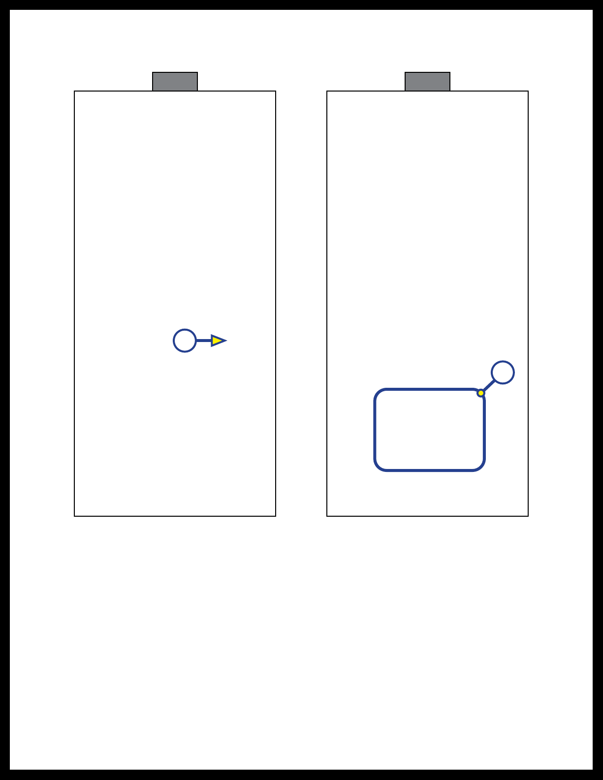
C. Touch and hold the controller's RAISE button (Fig. 7A) to fully extend the bimini top.
Note: Do NOT fully open the QC bimini system without the canvas top installed or failure of the system
willresult.
I. The controller's operation indicator light will turn on green (Fig. 7B).
II. The light will turn off after the system has completed its travel.
D. Touch and hold the controller's LOWER button (Fig. 8A) to fully retract the bimini top.
I. The controller's operation indicator light will turn on blue (Fig. 8B).
II. The light will turn off after the system has completed its travel.
E. Alternately operate the controller's RAISE and LOWER buttons to place the bimini top in various
positions to ensure proper QC controller installation.
Using the Bluetooth® Compatible App
The SureShade app operates in the same fashion as the physical controller. There is no operation indicator
light on the control button screen.
If using an iOS (Apple) smart device, do as follows:
1. Search the App Store for the SureShade Connect app.
Note: When using SureShade as the search criteria, more than one SureShade app may appear (Fig. 9).
Make sure to select SureShade Connect (Fig. 9A).
A. Install and open the app.
B. Tap the I Accept button (Fig. 10A) to accept the License Agreement.
Fig. 7 Fig. 8

Rev: 01.20.22 Page 10 CCD-0004551
App Store®is a trademark of Apple Inc. AndroidTM and Google PlayTM are trademarks of Google LLC.
A
A
Fig. 9 Fig. 10

Rev: 01.20.22 Page 11 CCD-0004551
C. Read the Proper Bimini Use and Care and Maintenance statements (Fig. 11A), then tap the
Continue button (Fig. 11B).
D. Tap OK for Bluetooth (Fig. 12A).
B
A
A
Fig. 11 Fig. 12
Rev: 01.20.22 Page 12 CCD-0004551
A
LED Blinks
Turquoise
A
B
E. Tap the Connect button (Fig. 13A).
F. Follow the SureShade Connection Steps (Fig. 14A), then tap Continue (Fig. 14B).
Fig. 13 Fig. 14

Rev: 01.20.22 Page 13 CCD-0004551
G. Select the desired bimini from the Available Biminis list (Fig. 15).
H. The Touch Controller will begin pairing itself with the smart device (Fig. 16).
Fig. 15 Fig. 16
Rev: 01.20.22 Page 14 CCD-0004551
A
I. Tap the Pair button (Fig. 17A) to complete the connection.
J. The controller and the paired smart device are now connected and the Raise and Lower buttons
are now active (Fig. 18).
Buttons
are
Active
A
Fig. 17 Fig. 18
Rev: 01.20.22 Page 15 CCD-0004551
K. Tap and hold the Raise button (Fig. 19A) to extend the bimini top.
Note: Do NOT fully open the QC bimini system without the canvas top installed or failure of the system
willresult.
L. Tap and hold the Lower button (Fig. 20A) to retract the bimini top.
M. Alternately operate the app's Raise and Lower buttons to place the bimini top in various positions
to ensure a good Bluetooth connection.
Only open the bimini top indoors when testing for proper installation. Opening the bimini top
outdoors subjects the system to possible strong winds that could result in severe product damage.
Only open the bimini top indoors when testing product for proper operation.
A
Fig. 19 Fig. 20
A
Rev: 01.20.22 Page 16 CCD-0004551
A A
B
Fig. 21 Fig. 22
2. To disconnect and unpair the iOS smart device from the connected controller, do as follows:
A. With the app open to the Raise and Lower button screen (Fig. 18), tap the gear icon (Fig. 18A) to
access the Settings screen (Fig. 21).
B. Tap the slider button (Fig. 21A) to turn Auto-Reconnect on so the smart device will always
automatically reconnect with the controller.
C. Tap the slider button again to turn Auto-Connect off (Fig. 22A).
D. Tap the Unpair button (Fig. 22B) for the paired/connected shade.
Rev: 01.20.22 Page 17 CCD-0004551
A
E. The Paired Shades screen (Fig. 23) will reflect the removed shade.
F. Tap the Back arrow (Fig. 23A) to return to the Connect screen (Fig. 13).
Fig. 23

Rev: 01.20.22 Page 18 CCD-0004551
A
A
If using an Android smart device, do as follows:
1. Search the Google Play Store for the SureShade Connect app.
Note: When using SureShade as the search criteria, more than one SureShade app may appear (Fig. 24).
Make sure to select SureShade Connect (Fig. 24A).
A. Install (Fig. 25A) and open the app (Fig. 26).
Fig. 24 Fig. 25
Fig. 26
Rev: 01.20.22 Page 19 CCD-0004551
Fig. 27 Fig. 28
A
B
A
B. Tap the I Accept button (Fig. 27A) to accept the License Agreement.
C. Read the Proper Bimini Use and Care and Maintenance statements (Fig. 28A), then tap the
Continue button (Fig. 28B).
Rev: 01.20.22 Page 20 CCD-0004551
Fig. 29 Fig. 30
A
A
D. Tap OK (Fig. 29A) in the Permissions Request window.
E. Tap the desired option (Fig. 30A) to grant the app access to the device's location.
Note: Lippert recommends selecting the "While using the app" option.
Table of contents
Popular Boating Equipment manuals by other brands


Dock Doctors
Dock Doctors Paddle Products Beach Dolly Assembly instructions

Quick
Quick PRINCE DP2E Series user manual

Roswell
Roswell Bennington C924-016650 Care, Maintenance, Operations

monster tower
monster tower HS-1 Mounting instructions

SeaView
SeaView PMA-DM124-M2 installation instructions

ZF
ZF 4-1 M operating manual