140133-00 | 02/19
Dowco Marine, Inc. | 1610 Frisco Drive, Lebanon MO 65536 | dowcomarine.com | (800) 404-5252
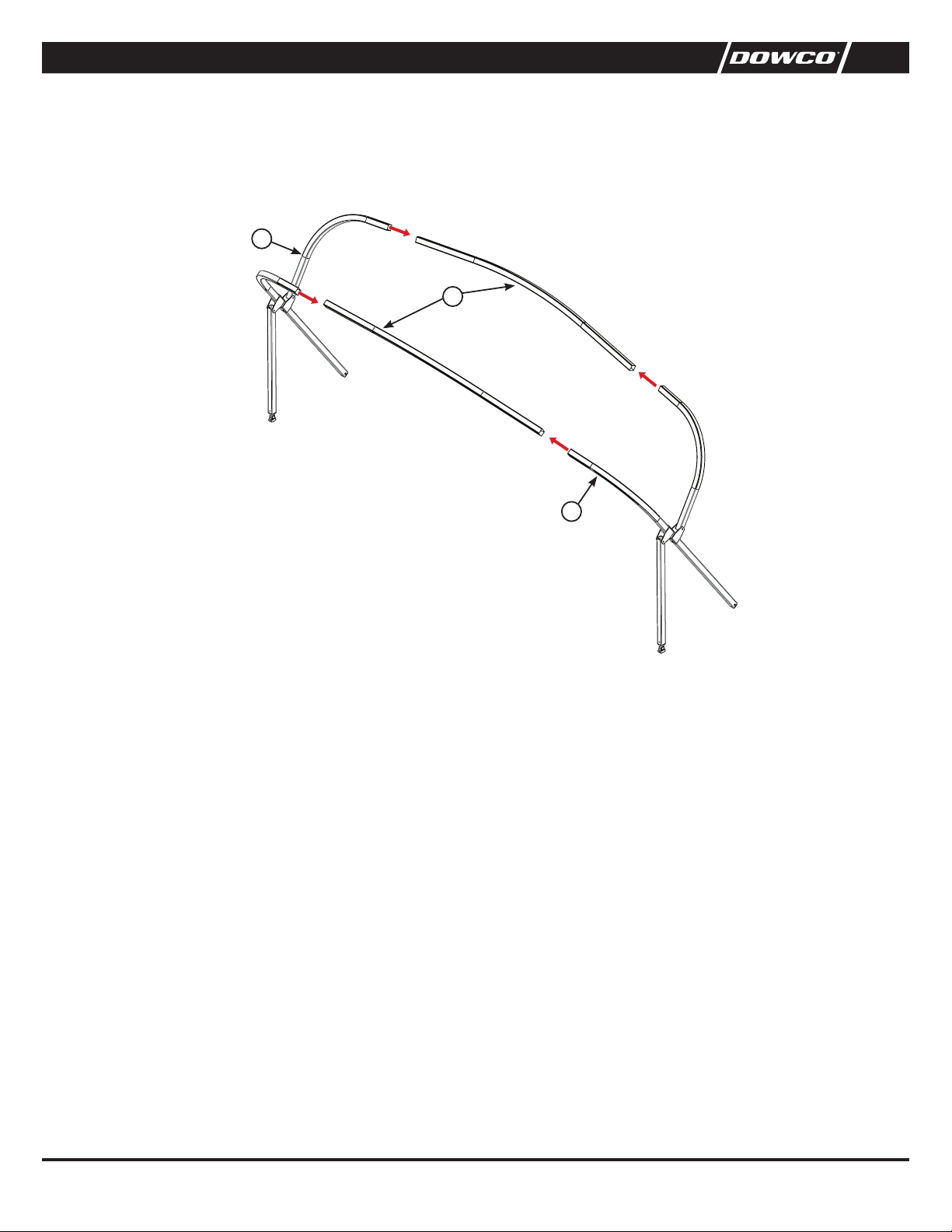
STEP 1
Bracket location (A). Measure and place a mark on the top rail 102" forward from a main bracket. Button location (B). Measure and place a
mark on the top rail 26" forward from (A).
STEP 2
Center the brackets/buttons at each mark as shown in Figure 2. Transfer the centers of each hole at the bottom of the bracket on to the rail
using a center punch.
STEP 3
Using ⁄" drill bit, drill holes completely through the top rail.
STEP 4
Replace the brackets. Insert a 1 ¾" bolt from the top through the bracket and the rail. Place a barrel nut on each bolt and tighten (Figure 2).
STEP 5
Follow the same procedure for the other side.
BRACKET LOCATIONS & ASSEMBLY (FIGURES 1 & 2)
NOTE:
Your pontoon has been pre-assembled with an a canopy and a canopy frame from G3. The a canopy that is supplied with the pontoon is
not designed to be used with an enclosure. You must remove the standard a canopy and replace it with the a canopy that is supplied with the
purchase of your enclosure. Once the new canopy is installed, raise the entire unit to the "up" position. Make sure the a canopy is centered on the
frame between the port and starboard sides. This step is very critical, it will determine the final appearance of your completed enclosure.
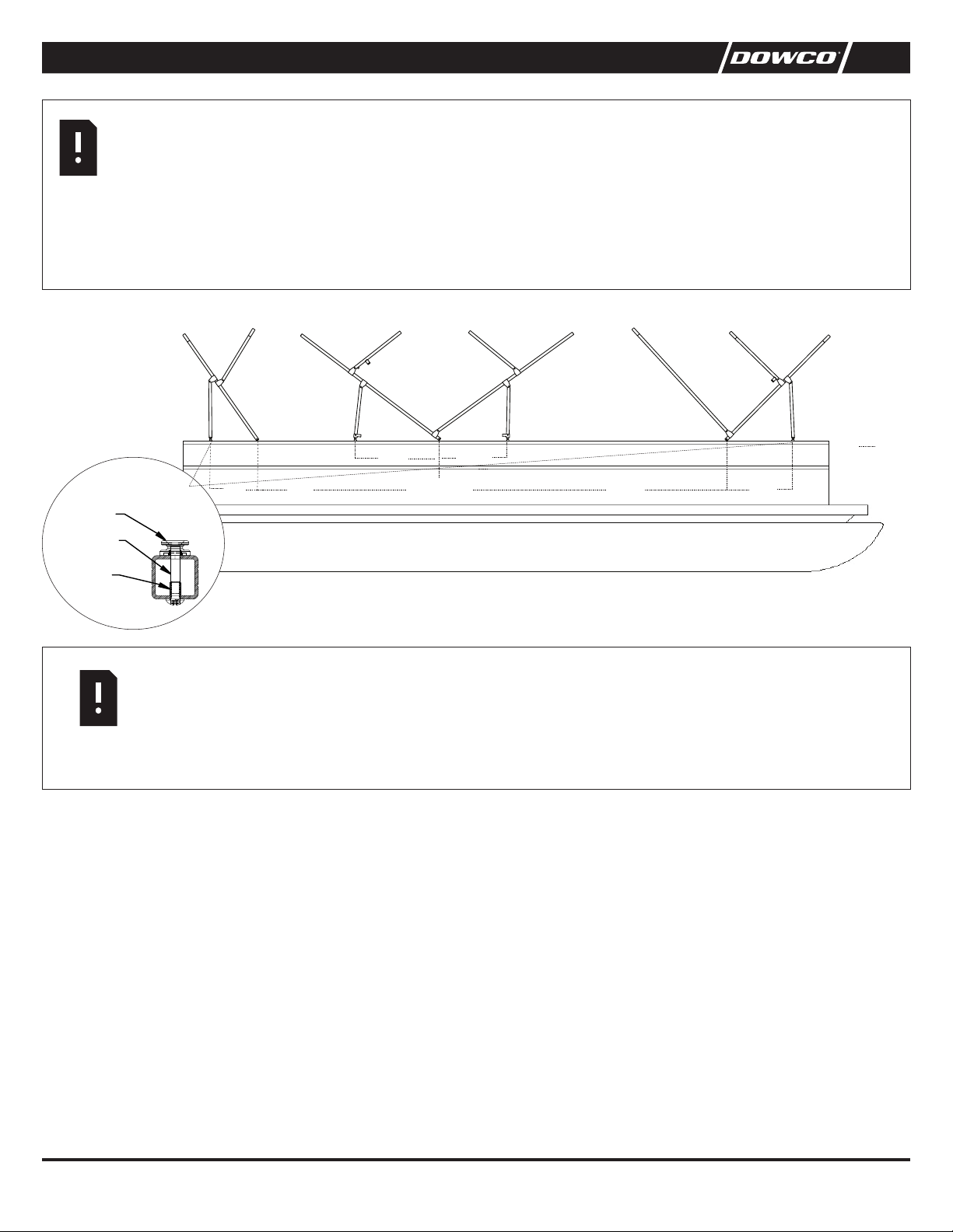
FIG. 1
122”
TO BACK OF DECK
29.5” 20”
19 ”
102”
MAIN
AFT BOW
EXT. AFT
(NOT REPRESENTATIVE OF ACTUAL BOAT)
AB
31” 48”
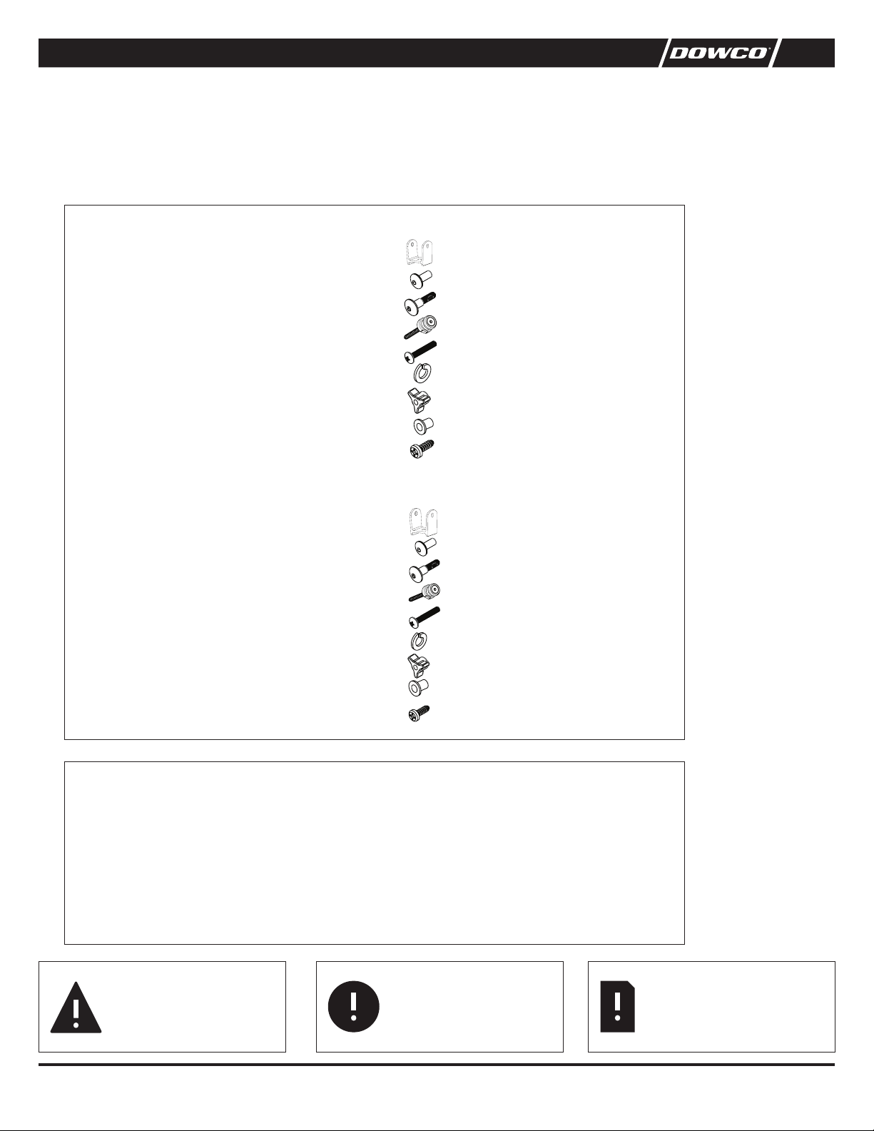
BUTTON MOUNTING DETAIL
DECK BUTTON
1/4-20 x 1 1/2
CSINK FASTENER
1/4-20 x 3/4
BARREL NUT
NOTE:
This enclosure is designed to fit the 2013 G3 X 24RS Pontoon Boat that has the a canopy brackets in the following locations:
Main Bracket from back 122" Rear HDA 29.5" FWD HDA 20"
Measurements should be taken from the main bracket of the a canopy bracket as shown below for bow and extended a brackets/hinges.
If brackets are off more than 1 inch in either direction, the enclosure WILL NOT FIT.
All measurements are taken to the center of the brackets.