FOLDING
& LOWERING THE
TOWER IS A TWO PERSON
OPERATION. BEFORE UNLOCKING
THE TOWER ENSURE SOMEONE IS
READY TO HELP FOLDTHE TOWER SAFELY.
INSERT LEVER TO UNLOCKTOWER.
TURN LEVER CLOCKWISE UNTIL IT STOPS.
THIS IS THE RESET POSITION. TO LOCK TOWER,
INSERT LEVER AND TURN
COUNTERCLOCKWISE.
WHEN TOWER IS UPRIGHT,
SAFETY HANDLES MUST BE
INSTALLED.
ONLY REMOVE HANDLESTO FOLD &
LOWER TOWER.
3
Bennington Tower Care/ Maintenance/ Operations www.roswellmarine.com
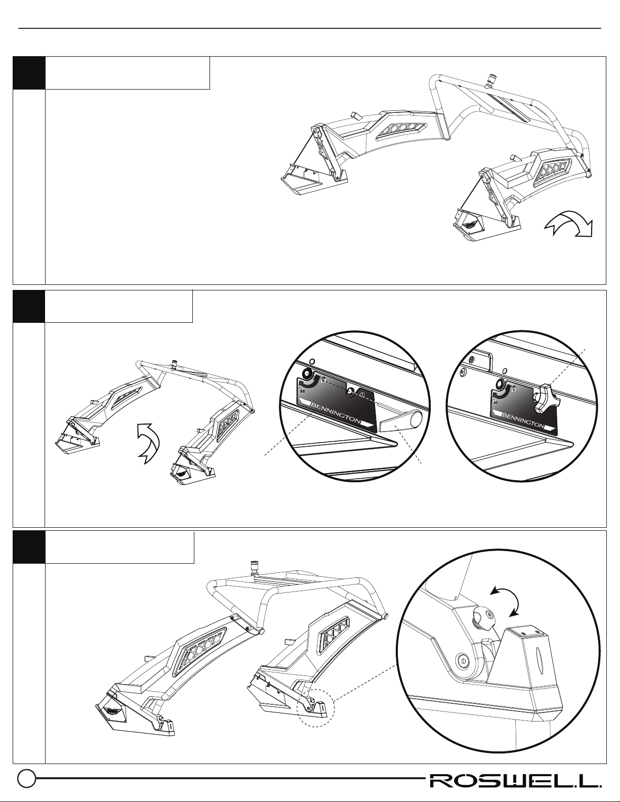
BSafety
Handle
Remove your 2 safety handles
Unlocking the latches
C
Folding Your Tower
Unscrew the safety handles from each side
of the tower. Store them some place safe
until you fold your tower back up.
Insert the Latch lever into the hole illustrated and follow the instructions
indicated on the decal. The decal instructions are dierent on each side.
Prior to unlocking the second latch ensure your helper is ready to
support and slowly lower the weight of the tower.
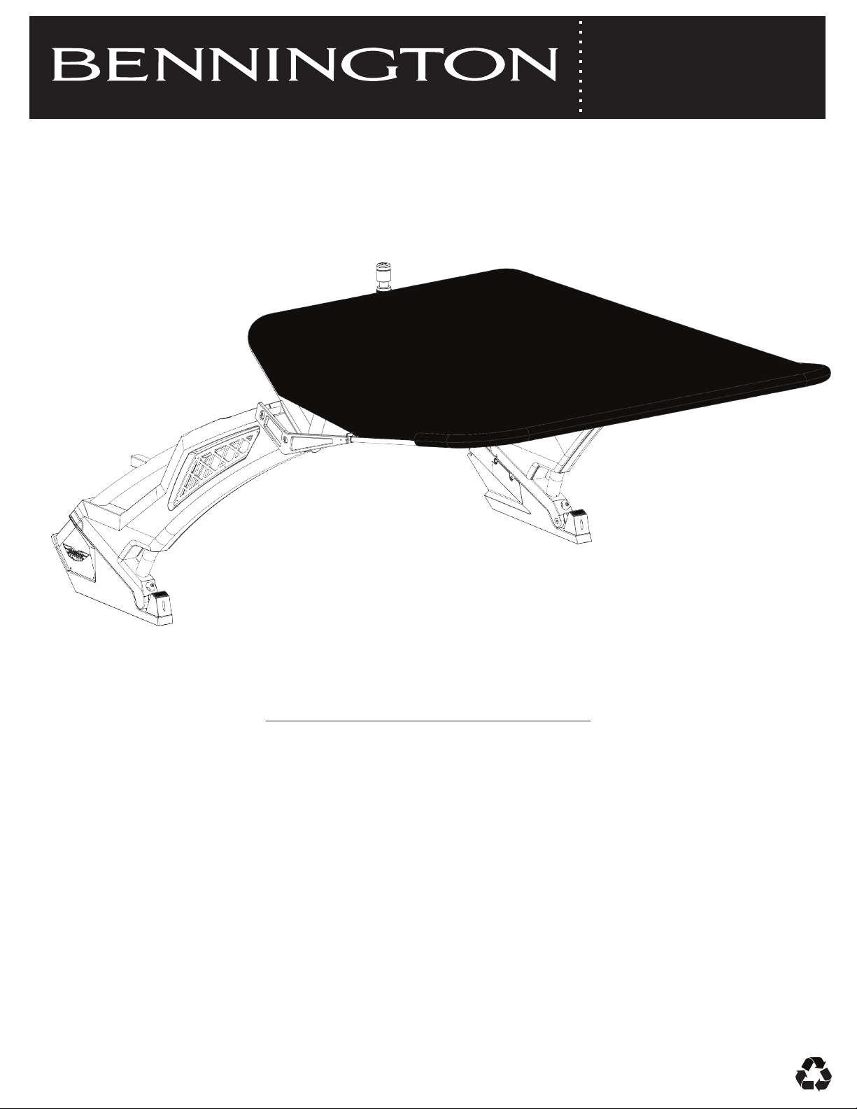
BEFORE ATTEMPTING TO FOLD YOUR TOWER :
- Ensure two people are present. This is a two person operation.
- Ensure all boards have been removed from racks.
- Ensure swivels are locked into either the inside or outside positions.
- Ensure your bimini is folded against the tower and secured.
- Ensure no body parts are near the folding area of the tower.
- Ensure that no one is sitting in the way of the folded tower.
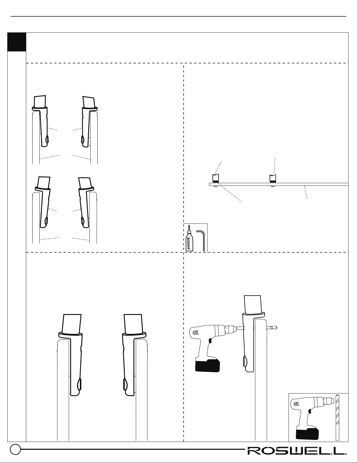
A
STARBOARD Side Unlocking:
Insert and turn lever COUNTERCLOCKWISE until it stops.
This is the reset position.
STARBOARD Side Locking:
Insert and turn lever CLOCKWISE.
PORT Side Unlocking:
Insert and turn lever CLOCKWISE until it stops.
This is the reset position.
PORT Side Locking:
Insert and turn lever COUNTERCLOCKWISE.
FOLDING
& LOWERING THE
TOWER IS A TWO PERSON
OPERATION. BEFORE UNLOCKING
THE TOWER ENSURE SOMEONE IS
READY TO HELP FOLD THE TOWER SAFELY.
INSERT LEVER TO UNLOCKTOWER.
TURN LEVER CLOCKWISE UNTIL IT STOPS.
THIS IS THE RESET POSITION. TO LOCK TOWER,
INSERT LEVER AND TURN
COUNTERCLOCKWISE.
WHEN TOWER IS UPRIGHT,
SAFETY HANDLES MUST BE
INSTALLED.
ONLY REMOVE HANDLESTO FOLD &
LOWER TOWER.
Latch
Lever
Instruction
Decal