Lippert Components 13398-C1 Operation manual

Schwintek in-wall™Slideout SyStem
operation and Service manual
LIPPERTCOMPONENTS, INC.
Contents
I. Controls
1-1 System components 1
1-1A versions C1 & C2 2
1-2 Motor wiring harness connections 3
1-3 Extend and retract switch connections 3
1-4 Power to board 4
1-5 Board overview 4
1-6 Manual mode -jog 5
1-7 Manual mode -stall force calibration 5
1-8 Error codes 5
1-9 Motor direction switches 7
1-10 System schematic 7
II. Motors
2-1 Manual override 8
2-2 Motor disengagement 8
2-3 Motor replacement 10
2-4 Slide mechanism replacement 13
III. Troubleshooting
3-1Troubleshootingowchart 15
I. CONTROLS - VERSIONS B, C, C1 & C2
1-1 System components
motor 1 slide controller motor 2
motor wiring harnesses
Rev-C motor and Controller components install exactly as Rev-B. However, Rev-B
components are not to be used with Rev-C components. Rev-C2 components are shown in Fig. 1.
REV-C Motor
REV-C Controller
Fig. 1
reve030911

1-1A CONTROLLER VERSIONS C1 & C2
NewcontrolcongurationsforversionC1&C2,seebelow:
1-1A.1 CONFIGURATION
1. Press button 2x and hold 3rd for 5 seconds to enter manual mode.
2. Press button 4x and hold 5th for 5 seconds to enter stall threshold calibration mode.
3. Press button 6x and hold 7th for 5 seconds to Override mode.
1-1A.2 MANUAL MODE
1. Green Led blinks once, wall switch controls motor 1.
2. Press button, Green Led blinks twice, wall switch controls motor 2.
3. Press button, Green Led solid, wall switch controls motor 1 and 2.
4. Press and hold button to exit.
1-1A.3 STALL THRESHOLD CALIBRATION MODE
1. Use Pot to turn stall threshold up/down.
2. Press button to save and exit.
1-1A.4 OVERRIDE MODE
1. Use the extend/retract switch to move both motors in/out all pulse counting, and stall are
disabled in this mode.
2. Over-current and short circuit detection are still active to help prevent damage to the board.
3. To exit the mode, push and hold the push button switch until the LEDs begin to blink
simultaneously.
Exiting the override mode resets the motor positions.
I. CONTROLS - VERSIONS C1 & C2
Version C1 maintains the same motor
harness connector to the controller as
in version C. However, the connector at
the motor has been insulated with a new
molded shield to protect against external
damage.
Version C2 motor harnesses have molex
connectors at the controller and the mold-
ed connector at the motor end.Wire colors
match with color codes on control board.
NOTE: It doesn’t matter which motor is 1
or 2.
2

1-2 Motor wiring harness connections
NOTE: Ribs on motor connector line up with notch in side of male connector on wiring harness.
Color codes on wires also match (black to black, red to red, etc.).
1-3 Extend and retract switch connections
NOTE: Direction control switch (customer supplied)
Common connection on control board goes to common connection on extend and retract switch. The
extend and retract connections on the control board go to the extend and retract terminals on the
switch. Power is supplied to switch from any nearby 12VDC power source.
3
Correctly connected motor
1-4 Power to board
¼ spade terminals are provided for power into the board. (Voltage range 8vdc to 18vdc).12 vdc is
recommended. Lower voltages reduce available power to room slide. 10ga wire is the minimum size
recommended.
1-5 Board overview

Status led’s - 2 led’s, 1 green and 1 red, are provided to indicate current controller status and faults.
Motor direction switches - Used to change direction of motors, 2 are provided, 1 for each motor.
Mode button - Places controller in manual mode, for jogging individual motors. Places controller
in calibration mode, where stall current can be increased or decreased or returns controller to auto
mode.
Power source - 12 volt dc input. Unit will operate from 8 volts dc to 18 volts dc.
Motor 1 connector - Power and encoder input for motor 1.
Direction switch connector - Provides input from customer supplied extend and retract switch.
Stall calibration - Allows for adjustment of stall force.
Motor 2 connector - Power and encoder input for motor 2.
1-6 Manual mode -Jog
Press mode button 2 times quickly, press a 3rd time and hold for approximately 5 seconds. The green
ledwillashonandoff.Manualmodenowactiveformotor#1.Usingtheextendandretractswitch,
motor 1 can be jogged manually.
Pressthemodebutton1moretimeandthegreenledwillashonandoff.Manualmodeisnow
switchedtomotor#2.Theextendandretractswitchwillnowjogmotor#2.
When both motors have been jogged to the desired position, exit manual mode by pressing and
holdingthemodebuttonuntilbothredandgreenled’sstarttoash.Thecontrolisnowbackinauto
mode.
1-6. 2 Units with the C1 board “electronic” manual override.
In the event of any fault code,theunitcanbemanuallyoverriddenelectronicallyusingthesesteps:
1. Locate the circuit board
2. Press the “mode button” six times quickly, press a 7th time and hold for approximately 5
seconds.
3.TheredandgreenLEDlightswillbegintoashindicatingyouareinoverridemode
4. Using the wall switch, press and hold the “in” button until the unit comes completely in.
status led’s motor direction switches mode button power connection
motor 1 connector motor 2 connector
direction switch stall calibration
4

1-7 Stall force calibration
If the system stalls out before reaching end of stroke, or if the room doesn’t seal as tightly as desired,
then stall force may be increased.
***CAUTION***
IF ROOM STALLS MID STROKE, MAKE SURE THAT THERE ARE NO OBJECTS IN THE WAY,
OR THAT SOMETHING HAS BEEN PULLED INTO THE SYSTEM, CAUSING RESTRICTED
MOVEMENT. ALSO CHECK SYSTEM VOLTAGE. EVEN THOUGH THE SYSTEM CAN RUN ON
AS LITTLE AS 8VDC, THE FORCE AVAILABLE TO MOVE THE ROOM IS REDUCED ON LOWER
VOLTAGE. IF THE ROOM IS FREE OF OBSTRUCTIONS AND VOLTAGE IS SUFFICIENT (12VDC)
AND THE SYSTEM STILL STALLS MID STROKE, ONLY THEN SHOULD STALL FORCE BE
INCREASED.
Press mode button 4 times quickly, then press a 5th time and hold for approximately 5 seconds. The
redledwillstarttoash,ash,ash,…Breakthesealonthecoveroverthestallforcecalibration
hole. Directly below the sealed hole is a potentiometer. Using a small screwdriver increase the stall
force by turning clockwise, turning counter-clockwise will reduce stall force. Once the desired setting
has been reached press the mode button and both led’s will light up. The board is now back in auto
mode.
It is desirable to increase the stall force only enough to insure proper functioning of the room.
Increasing the setting beyond the amount needed only shortens system life.
Caution!
During this override procedure the motors are not synchronized. Visually watch
the room, if one side is moving signicantly slower then the other (or not at all)
then immediately stop and use the “motor disengagement” override method.
5
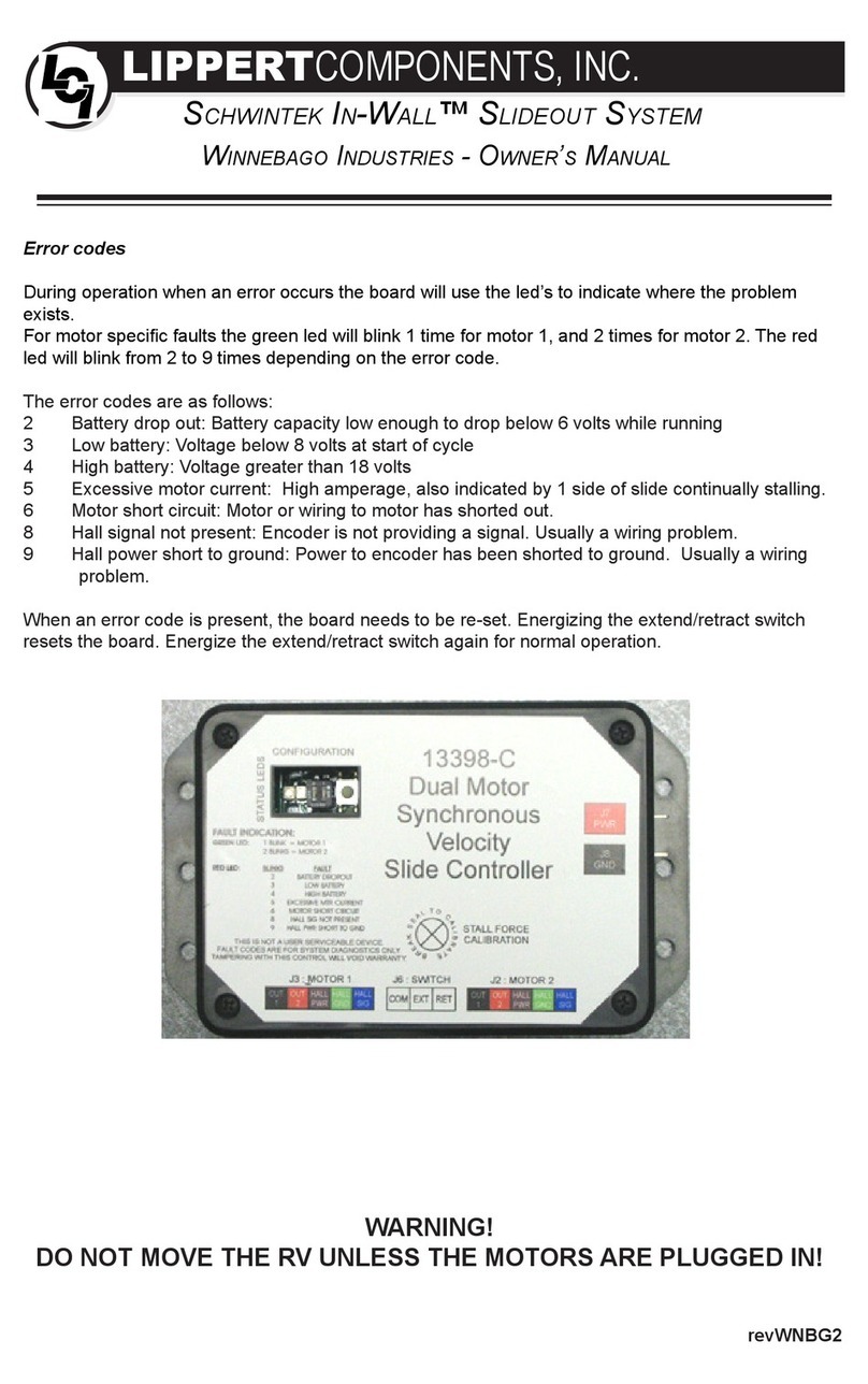
1-8 Error codes
During operation when an error occurs the board will use the led’s to indicate where the problem
exists.
Formotorspecicfaultsthegreenledwillblink1timeformotor1,and2timesformotor2.Thered
led will blink from 2 to 9 times depending on the error code.
Theerrorcodesareasfollows:
2 Batterydropout:Batterycapacitylowenoughtodropbelow6voltswhilerunning
3 Lowbattery:Voltagebelow8voltsatstartofcycle
4 Highbattery:Voltagegreaterthan18volts
5 Excessivemotorcurrent:Highamperage,alsoindicatedby1sideofslidecontinually
stalling.
6 Motorshortcircuit:Motororwiringtomotorhasshortedout.
8 Hallsignalnotpresent:Encoderisnotprovidingasignal.Usuallyawiringproblem.
9 Hallpowershorttoground:Powertoencoderhasbeenshortedtoground.Usuallyawiring
problem.
When an error code is present, the board needs to be reset. Energizing the extend/retract switch
resets the board. Energize the extend/retract switch again for normal operation.

1-9 Motor direction switches
red led green led mode switch
motor direction
switches
Motor direction switches are used to change the direction of individual motors. If when trying to
extend or retract the room, one side goes in and the other side goes out, then there is a problem in
the wiring. The motor direction switches can be used to correct this problem. The left switch controls
motor 2 and the right switch controls motor 1. If motor 1 is going in the wrong direction then change
switch 1’s position. If motor 2 is going in the wrong direction then change switch 2’s position.
The motor direction switches can also be used to change the direction of the extend/retract switch. If
the room extends when the extend/retract switch is moved to the retract position, it’s direction can be
reversed by moving both switch 1 and switch 2 to their opposite positions. This feature can be used if
it is more convenient to change the motor direction switches than to rewire the extend/retract switch.
6
II. Motors
2-1 Motor disengagement
Ifmotorsneedtobedisengaged,followthesesteps:
1. On the outside of the room, approximately 2 inches above the top guide rack there is a motor
retention screw. Remove this screw.
2. Directly above the rack, pull back the weather stripping to expose the bottom of motor. Insert a
screwdriver between the motor and it’s mount and pry the motor up.

1-10 System schematic Revisions B - C - C1
7

8

*************Do not move the rv with the motors disengaged.*************
5.Ifthervneedstobemoved,atravellockwillneedtobemadeasfollows:Withtheroomclosed,
cut a board 1 inch longer in length than the distance between the interior stop and the wall. Wedge
thisboardtightlybetweenthewallandstoptolock1sideoftheroom.Cutanotherboardtotthe
other side of the room and wedge into place. This should lock the room in the retracted position,
allowing the rv to be moved.
Alternately several ratchet straps may be used,
wrapping completely around the rv, and room,
then pulled tight. Depending on the size of the
room, straps with a 500 to 1000 pound capacity
will be required.
**********Do not move the rv unless the motors are plugged in.*************
9
3. Lift the motor approximately 1 inch, tighten the motor retention screw to hold the motor in it’s
raised position.
4. The motor is now disengaged. Repeat these steps on the other side of the room. The room
should move freely, and can be pushed in or out as desired.

10
2-2 Motor replacement
1. If a motor needs replacement follow steps 1 through 4 for motordisengagement.
2. With the motor disengaged place support under the room. Wedges, a jack, or forklift may be
used.
3. Once the room is supported, remove the screws retaining the side column to the outside face
of the rv.
4. Slightly raise the room to remove any weight from the side column. It is now possible to slide
the side column out of the wall, it may be necessary to use a pry bar to start the column
moving. Slide the column out until it is past the outside face of the wall.
5. Remove the motor retention screw and lift the motor out the top of the side column.
6. There is a coupler, which connects the motor to the drive mechanism. If the coupler is still
attached to the motor, it may be removed with pliers.
Ifitisstillinsidethecolumn,proceedasfollows:
a. On the bottom, inside of the column is the opposite end of the drive shaft. Using a piece of
wood or brass push the shaft up approximately 1-inch.

*********Do not push shaft up further than 1 ½ inches.************
b. The coupler will be lifted above the motor mount and can be removed with a pair of needle nose
pliers or hemostats.
7. The coupler needs to be placed onto the end of the drive shaft, inside the motor mount, at the
top end of the column. Note the splines on the drive shaft and motor coupler.
11
The coupler can be rotated while pushing down, or the side column can be pushed back and forth
while pushing down, to engage the splines. The coupler should be pushed down below the top of the
motor mount.

12
8. The motor can now be installed. Insert the motor through the top of the side column. Note the
screws protruding from the shaft end of the motor. They enter into the 2 holes in the corners of
the motor mount. Pay attention to the orientation of the screws and mating holes.
9. Align the motor shaft with the hole in the coupler, the motor should drop part of the way into the
coupler. While pushing down on the motor, slide the side column back and forth on the racks to
rotatethecouplerandalignthecoupleratwiththeatonthemotorshaft.Whentheatslineup,
the motor will drop down onto the motor mount.
10. Replace the motor retention screw.

3. The new side column assembly can now be installed. Remove the motor and re install the coupler.
(see 2-3 Motor replacement) This is easier to do before the column assembly is installed.
4. On the side of the column facing towards the room, there is a v-roller, a gear above the roller and
a hook, with a plastic shoe, above the gear.
13
11. Tuck the motor wires inside the side column. The column can be slid back along the racks,
and into the opening in the wall. There will be some resistance from the motor.
12.Withthesidecolumnmountingangepushedagainsttheoutsideofthewall,themounting
screws can be replaced.
13. Plug the motor back in.
2-3 Slide mechanism replacement
1. Follow steps 1 through 4 for motor replacement.
2. With the motor disengaged, and the side column detached from the side wall, remove the
exterior T-molding. Slide the side column along the racks towards the outside, until the column
separates from the racks.

Thehookslidesintoahookshapedslotonthetopedgeoftheracks.Thev-rollertsintoavshaped
grove on the bottom edge of the rack. The gear meshes with the rack teeth on the outside face of the
rack.
Start the top hook on the side column into the hooked slot on the top gear rack on the side of the
room. Start the bottom hook on the side column into the hooked slot on the bottom gear rack on the
side of the room. Slide both top and bottom in until the 1
st
gear tooth is just touching the 1
st
tooth on
the end of both the top and bottom racks. The v-rollers should be close to touching the v shaped slot
in the bottom of both racks.
5. Push evenly on both the top and bottom of the side column, engaging the gear teeth into the rack
teeth of both top and bottom racks at the same time. Continue to slide the side column onto the
racksuntiltheweatherstriponthefrontfaceofthesidecolumnisushwiththeendoftheracks.
Bothtopandbottomracksshouldcomeushatthesametime.Iftheracksare1toothoutoftime
with each other there will be a 3/16 difference in the end position of the racks.If both top and
bottomareush,continue.Ifbothtopandbottomarenotush,thenpullthesidecolumnoutto
disengagethegearsandrepeatuntilbothtopandbottomgearracksareushatthesametime.
6. Push the side column along the racks until it is close to the outside face of the wall.
7. Follow steps 8 through 13 for motor replacement (Motor replacement 2-3).
14

III. Troubleshooting
3-1 Trouble shooting ow chart

3-2 Checking Fuses
The Total Control 1Slide requires a minimum of 30 amp fuse. Check the 12 volt fuse box for blown
fuses, and replace any if necessary. Consult the rv manufacturers documentation for the location
of the 12 volt fuse box, and the location of the Room Slide Controller’s fuse. If the fuse blows
immediately upon replacement, there is a problem with the wiring to the In-Wall™Slide control box.
Havequaliedservicepersonnelcheckandrepair.
3-3 Obstructions
Checkoutsidethervforpossibleobstructions:tree,post,car,ect…Checkinsidethervforany
obstructions:luggage,furniture,opencabinets,ect…Alsocheckforsmallerobjectsthatmaybe
wedgedundertheoororinthesidesofunit.Removeobstructionsbeforeproceeding.
3-4 Error Codes
Consult rv manufacturer’s documentation for the location of the Total Control 1 Slide Controller. See
page 1-8 for a description of the error codes, and possible problems.
3-5 Low Voltage
The Total Control 1 Slide Controller is capable of operating the room with as little as 8 volts. But
at these lower voltages the amperage requirement is greater. Check voltage at the controller, see
page C-5 for the location of power connections. If voltage is lower than 11 volts, it is recommended
that the battery be placed on a charger until it is fully charged. It may be possible to ’jump’ the rv’s
battery temporarily to extend or retract the room. Consult the rv manufacturer’s owners manual on the
procedure for ‘jumping’ or charging the battery.
**********Never ‘jump’ or charge the battery from the power connections
on the In-Wall™Controller. Always do this at the battery.*****************
3-6 Only 1 side moving
The Total Control 1 Room Slide has a separate motor to operate each side of the room. Does only 1
side of the room move a short distance (2 to 4 inches) and stop.
3-7 Will non moving side move with help
If only 1 side of the room is moving as in 3-6 above, then with someone’s assistance press the switch
to extend or retract the room while pushing the non moving side in the appropriate direction. On larger
rooms it may be necessary to have 2 or more people pushing the room.
3-8 Non moving side moved manually
Try to push the non moving side in and out. If a motor shaft has broken then it will be possible to
move that side of the room several inches by hand. Larger rooms may require several people to push.
3-9 With motor disengaged can room be moved?
Disengage motor, see 2-2 to disengage motor. After disengaging the motor is it possible to move the
room by hand? On larger rooms more than 1 person may be required to move the room.
3-10 Debris in the rack
Check all 4 gear racks on the side of the room for debris.
3-11 Do status led’s light
Consult the rv manufacturers documentation for the location of the Total Control 1 Controller. When
the room slide direction switch is actuated, do the status led’s light up. Check this in both the extend
and retract modes. See page 3 for the location of the status led’s. If the led’s do not light up, or
only light in 1 direction, then un-plug and re-plug the direction switch connection on the board. This
connection is shown on page 4. If the problem persists, the led’s still do not light up in both directions,
then the switch or the wiring between the switch and the room is defective.
3-12 Increase motor amperage
See page 4 for stall force calibration. Only increase stall force enough to cycle room effectively.
This manual suits for next models
1
Table of contents
Other Lippert Components Controllers manuals

Lippert Components
Lippert Components OneControl HVAC Control 2.0 User manual
Lippert Components
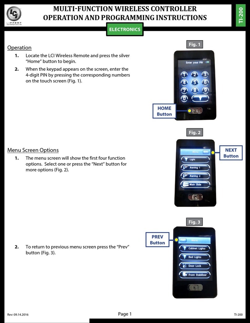
Lippert Components TI-200 Owner's manual
Lippert Components
Lippert Components 13398-C User manual
Lippert Components
Lippert Components ground control 3.0 User manual

Lippert Components
Lippert Components OneControl Tank Monitor V1 User manual
Lippert Components
Lippert Components Sway Command User manual
