CURTMFG.COM •PRODUCT SUPPORT: 877.287.8634 •18088-INS-RA •07/06/2021 •ECN7705 •PAGE 1
Product Registration and Warranty
CURT stands behind our products with
industry-leading warranties. To get copies
of the product warranties, register your
purchase or provide feedback, visit:
warranty.curtgroup.com/surveys
Weight Carrying Capacity
1 bike 65 lbs.
2 bikes 130 lbs.
INSTALLATION MANUAL 18088
Tools Required
Torx wrench, T-27
(included)
Box wrench,
13mm / 14mm
(included)
Hex drive wrench,
5mm (included)
--
Level of Difficulty
Easy
Installation difficulty levels are based on time
and effort involved and may vary depending on
the installer level of expertise, condition of the
vehicle and proper tools and equipment.
WARNING
Never exceed the vehicle manufacturer's recommended towing capacity.
Never exceed the product's weight capacity.
Do not modify or use this accessory for purposes other than for which it was designed.
It is the user's responsibility to adhere to all state and federal laws regarding
obstruction of vehicle lighting (i.e. brake lights, taillights, turn signals
and backup lights) and license plate when using this accessory.
NOTICE
Visit www.curtmfg.com for a full-color copy of this
instruction manual, as well as helpful videos, guides and much more!
Before you begin installation, read all instructions thoroughly.
Proper tools will improve the quality of installation and reduce the time required.
Remove this accessory before entering automatic car washes.
Periodic inspection of your product should be performed
to ensure all hardware and / or components remain secure.
CAUTION
This product is not designed for off-road use.
Do not install this product on a trailer or towed vehicle.
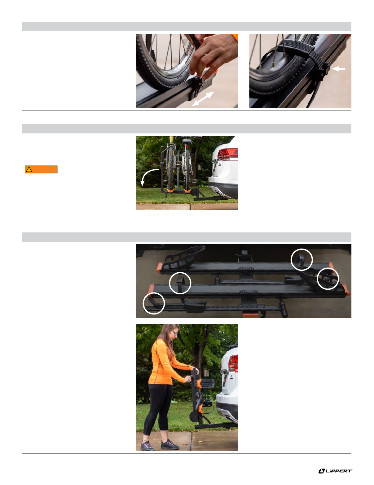
When transporting heavier bikes such as e-bikes and tilting the rack for rear vehicle
access is necessary, a team lift may be required to prevent injury and / or product damage.
Always be mindful of accessories extending beyond vehicle when operating.
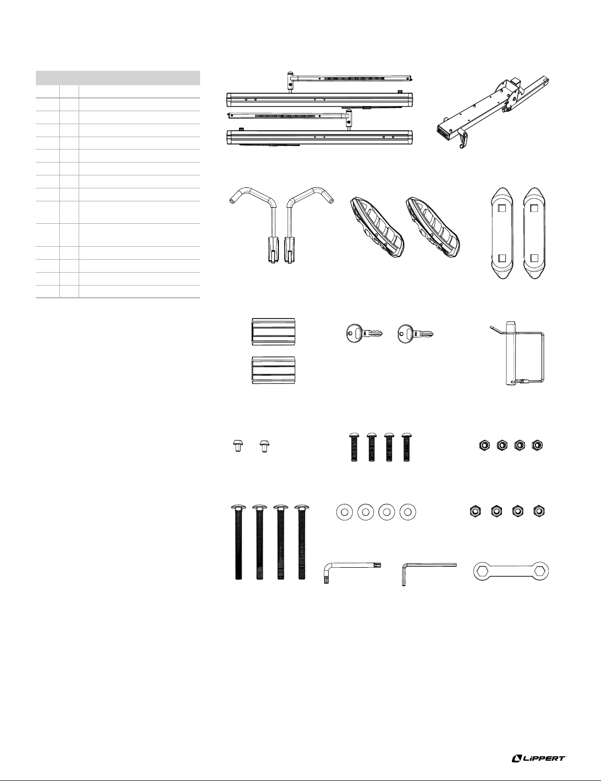
Parts List
Item Qty Description
1 2 Tray assembly
2 1 Shank assembly
3 2 Tire / frame hook assembly
4 2 Wheel basket
5 2 Tray spacer
6 2 Wheel strap sleeve
7 2 Key
8 1 Clevis pin, 1/2"
9 2 Button head cap screw,
M6–1.0 x 10mm
10 4Button head cap screw,
M8–1.25 x 35mm
11 4Nylock nut, M8–1.25
12 4Carriage bolt, 3/8"-16 x 4"
13 4Flat washer, 3/8"
14 4Nylock nut, 3/8"-16
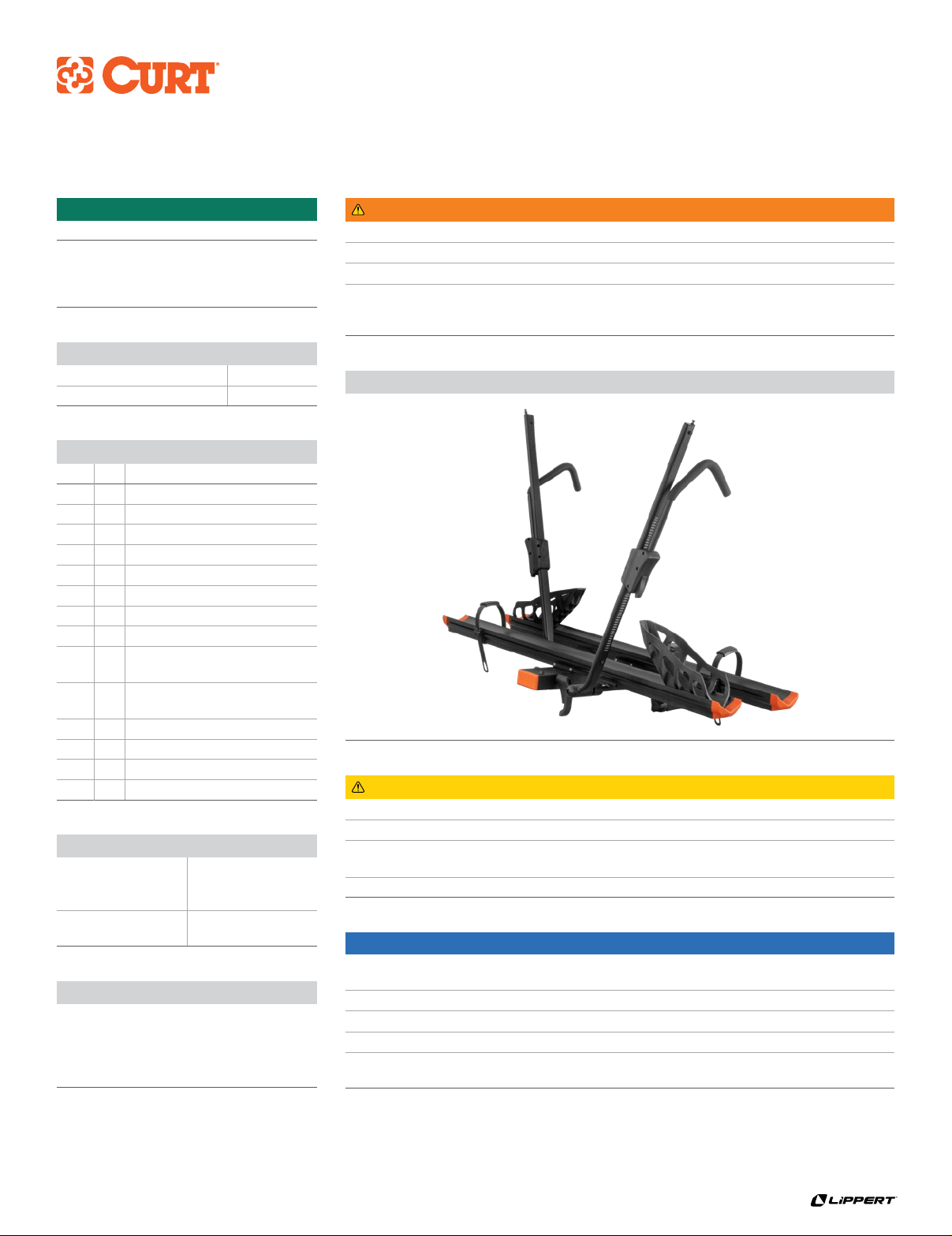
Product Photo