Lippert Cool SpaceRunner-LX800 User manual

TME-104P-CSR-LX800-R1V5.doc
Revision 1.5 / March 09
©LiPPERT Embedded Computers GmbH
Hans-Thoma-Str. 11
D-68163 Mannheim
http://www.lippertembedded.com/
Cool SpaceRunner-LX800
PC/104-Plus CPU Board
Technical Manual

Technical Manual Cool SpaceRunner-LX800
LiPPERT Document: TME-104P-CSR-LX800-R1V5.doc Revision 1.5
Copyright © 2009 LiPPERT Embedded Computers GmbH, All rights reserved
Contents and specifications within this manual are subject of change without notice.
Trademarks
MS-DOS, Windows, Windows 95, Windows 98, Windows NT and Windows XP are trademarks of
Microsoft Corporation. PS/2 is a trademark of International Business Machines, Inc. Intel and Solid
State Drive are trademarks of Intel Corporation. Geode is a trademark of Advanced Micro Devices.
PC/104 is a registered trademark of PC/104 Consortium. All other trademarks appearing in this
document are the property of their respective owners.

TME-104P-CSR-LX800-R1V5.doc Rev 1.5 i
Table of Contents
1Overview 1
1.1 Introduction .......................................................................................... 1
Features.................................................................................................. 1
Block Diagram.......................................................................................... 2
1.2 Ordering Information............................................................................. 3
Cool SpaceRunner-LX800 Models ................................................................ 3
Cable Sets and Accessories ........................................................................ 3
1.3 Specifications ........................................................................................ 4
Electrical Specifications ............................................................................. 4
Environmental Specifications ...................................................................... 4
Mean Time Between Failures ...................................................................... 4
1.4 Mechanical............................................................................................. 5
2Getting Started 6
2.1 Connector Locations .............................................................................. 6
Top ........................................................................................................ 6
Bottom.................................................................................................... 7
2.2 Jumper Locations................................................................................... 8
2.3 LED indicators........................................................................................ 9
2.4 Hardware Setup................................................................................... 10
3Module Description 11
3.1 Processor............................................................................................. 11
3.2 Companion........................................................................................... 12
3.3 Graphics-Controller.............................................................................. 13
SVGA Configuration ................................................................................ 13
VGA Connector....................................................................................... 14
LVDS Configuration................................................................................. 14
LVDS Connector ..................................................................................... 15
Backlight Connector ................................................................................ 15
Display Voltage Jumpers.......................................................................... 16
3.4 EIDE Solid State Drive ......................................................................... 16

TME-104P-CSR-LX800-R1V5.doc Rev 1.5 ii
3.5 Ethernet Controller .............................................................................. 17
Ethernet Interface .................................................................................. 17
3.6 On Board Power Supply ....................................................................... 18
Power Connector .................................................................................... 18
3.7 EIDE Port............................................................................................. 19
EIDE Connector ...................................................................................... 19
3.8 PS/2 Interface..................................................................................... 20
Keyboard and Mouse Connector ................................................................ 20
3.9 USB 2.0 Ports....................................................................................... 20
USB 2.0 Connector 1............................................................................... 21
USB 2.0 Connector 2/3/4......................................................................... 21
3.10 Serial Ports.......................................................................................... 22
COM1/2 Connector.................................................................................. 22
RS485-Termination Jumpers .................................................................... 23
3.11 Parallel Port LPT1 ................................................................................ 23
LPT1 Connector ...................................................................................... 24
3.12 Watchdog ............................................................................................ 24
3.13 LEMT functions .................................................................................... 24
3.14 Speaker ............................................................................................... 25
3.15 External Power-Button ........................................................................ 25
3.16 Reset-In Signal.................................................................................... 26
3.17 PC/104-Plus Bus Interface .................................................................. 26
3.18 PC/104 Bus Interface.......................................................................... 28
PC/104 Bus Connector............................................................................. 28
4Using the Module 29
4.1 BIOS .................................................................................................... 29
Configuring the XpressROM BIOS.............................................................. 29
Trouble Shooting BIOS Settings ................................................................ 37
4.2 Drivers................................................................................................. 37
4.3 LIVE LED Programming........................................................................ 38
4.4 Watchdog Programming ...................................................................... 39
4.5 Reading Temperatures......................................................................... 40

TME-104P-CSR-LX800-R1V5.doc Rev 1.5 iii
5Address Maps 41
5.1 Memory Address Map........................................................................... 41
5.2 I/O Address Map ................................................................................. 42
5.3 Interrupts............................................................................................ 43
5.4 DMA Channels...................................................................................... 43
5.5 PC/104 Bus Address Space.................................................................. 44
Appendix A, Contact Information A
Appendix B, Additional Information B
Appendix C, Getting Help C
Appendix D, Revision History D

TME-104P-CSR-LX800-R1V5.doc Rev 1.5 iv
Acronyms
ACPI Advanced Configuration and Power Management Interface
AES Advanced Encryption Standard
APM Advanced Power Management
ATA Advanced Technology Attachment
BIOS Basic Input Output System
BPP Bits Per Pixel
CD Compact Disc
COM Communication Equipment
CPU Central Processing Unit
CRT Cathode Ray Tube
CSR Cool SpaceRunner
DAC Digital-to-Analog-Converter
DDR Double Date Rate
DMA Direct Memory Access
DOT Dynamic Overclocking Technology
EIDE Enhanced Integrated Device Electronics
EMC Electromagnetic Compatibility
ETH Ethernet
FIFO First In First Out
FPU Floating Point Unit
FWH Firmware Hub
GPIO General Purpose Input Output
HDD Hard Disk Drive
I²C Inter-Integrated Circuit
IP Internet Protocol
ISA Industry Standard Architecture
LCD Liquid Crystal Display
LEMT LiPPERT Enhanced Management Technology
LED Light Emitting Diode
LPC Low Pin Count
LVDS Low Voltage Differential Signaling
MAC Media Access Control
MMU Memory Management Unit
PCI Peripheral Component Interconnect
PHY Physical Interface
PLL Phase-Locked Loop
PS/2 Personal System/2
PWR Power
SMB System Management Bus
SMC System Management Controller
SPI Serial Peripheral Interface
SSD Solid State Drive
SVGA Super Video Graphics Array
TCP Transmission Control Protocol
TLB Translation Look-aside Buffer
UART Universal Asynchronous Receiver Transmitter
USB Universal Serial Bus
UDMA Ultra-Direct Memory Access
UDP User Datagram Protocol
VGA Video Graphics Array
WDOG Watchdog

TME-104P-CSR-LX800-R1V5.doc Rev 1.5 1 (44)
1Overview
1.1 Introduction
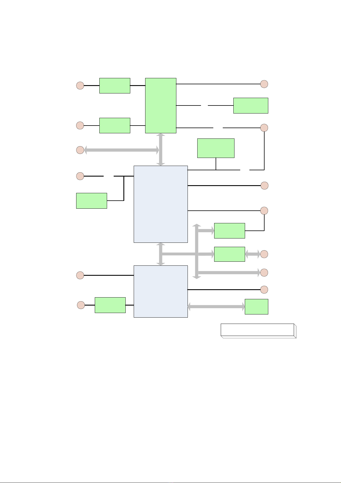
The Cool SpaceRunner-LX800 is a CPU-board for especially designed with rugged appliances in mind.
It allows the design of devices without moving parts. Additional resilience comes from the used
through-hole connectors.
The PC/104-Plus board with AMD’s Geode™ LX processor has a very good performance to power
ratio. The board comprises all peripherals needed for an embedded PC on a small 3.775" by 4.050"
printed circuit board. It is fully plug-in compatible with the Cool SpaceRunner 2, except that the Flat
Panel connector is replaced with three USB 2.0 ports.
The Cool SpaceRunner-LX800 integrates a powerful yet efficient AMD Geode™ LX800 processor
together with a CS5536 I/O companion and a Super I/O chip to form a complete PC, with all the
standard peripherals already onboard. There is a graphics controller with VGA and LVDS adapters to
connect different sorts of display terminals. Backlighting is provided for LCD modules too.
A fast 100/10BaseT Ethernet port, two RS232/RS422/RS485 serial ports, and four USB 2.0 host
ports handle the communication with external devices. There are PS/2 connectors for keyboard and
mouse as well as a parallel printer port available. An IDE ATA100 adapter allows connection of hard
disk or CD drives. Applications that require non-moving storage can use the integrated Solid State
Drive.
There is Solid State Drive (SSD) integrated, which is connected to the ATA-controller.
System expansion can easily be realized over PC/104, PC/104-Plus and I²C bus connectors.
The Cool SpaceRunner-LX800 is powered by a 5V-only supply and supports ACPI, advanced power
management and PCI power management. Security critical applications take advantage of the Geode
LX800 processor, too. It has an on-chip AES 128-bit crypto acceleration block capable of 44 Mbps
throughput on either encryption or decryption. The AES block runs asynchronously to the processor
core and is DMA based.
The Cool SpaceRunner-LX800 runs DOS, Windows, Linux and VxWorks operating systems.
Features
CPU
•AMD Geode™ LX [email protected] (500MHz)
•Cache Memory with:
•64 KB/64 KB level 1 I/D caches
•TLB (Translation Look-aside Buffer):
•128 KB level 2 cache
•Efficient Prefetch
Main Memory
•soldered DDR400 256MB
Chipset
•AMD CS5536 companion device
Extension slots
•1 x 32-bit PC/104-Plus
•1 x 16-bit PC/104 with full DMA capability
Interfaces
•Ethernet 10/100BaseT
•ATA-6 EIDE (Ultra DMA-100)
•PS/2 Keyboard/Mouse
•4 x USB 2.0 ports
•2 x RS232/RS485, software selectable
•1 x parallel port
•SVGA monitor
•18/24 Bit LVDS for displays
•MISC signals: external power button, I²C
bus, speaker, external reset button,
external battery connector
•Power supply
•Solid Sate Disk on PATA
Other configurations are possible at high volumes.

TME-104P-CSR-LX800-R1V5.doc Rev 1.5 2 (44)
Block Diagram
AMD Geode LX800
PCI -> ISA
ITE8888
PCI
Line Driver
LTC1334
SST FWH
SST25LF080A
Transmitter
DS90C383B Memory
256 MB
I/O Companion
CS5536
Super I/O
ITE8712
PCI
COM1
RS232/485
IDC 10
2.54 mm
VGA
IDC 10
2.54 mm
LVDS DF14
2 x 10 pin
1.25 mm
Backlight
DF13 8 pin
1.25 mm
EIDE
IDC 44
2.00 mm
PC/104 Plus
USB0
Ethernet1
IDC 10
2.54 mm
LPT/ Parallel
IDC 26
2.54 mm
PS/2-MS/KB
MISC
IDC 10
2.54 mm
SMB
SPI
ETH
Intel 82551IT
CSR-LX800 PC/104- Diagram
rev1v2 10072008CS
COM2
RS232/485
IDC 10
2.54 mm
Line Driver
LTC1334
PC/104
PS/2
EIDE
SMC
UPD78F0511GA
FWH
DF13 10 pin
1.25 mm
LPC
USB1/2/3
IDC12
2.54 mm
ISA
SSD
2GB

TME-104P-CSR-LX800-R1V5.doc Rev 1.5 3 (44)
1.2 Ordering Information
Cool SpaceRunner-LX800 Models
Order number Description
MHz), low power consumption, 256MB DDR SDRAM, 4x USB2.0, IrDA, RTC,
GoldCap, EIDE, 3x COM, LPT (EPP/EPC), PS/2 Keyboard, PS/2 Mouse, WDOG,
SMC, PC/104 bus, PC/104+ bus, VGA controller and LVDS Interface, Fast
Ethernet 100/10BaseT, EIDE 2 GB SSD
Operating temp. range: -40°C…+85°C
Cable Sets and Accessories
There are some options offered for the Cool SpaceRunner-LX800.
Order number Description
863-0014-10 Adapter Cable Set
Power, PS/2 keyboard and mouse, Ethernet and USB, VGA-CRT, 3x USB, COM1,
COM2, LPT, IDE (44 pin, 2mm), cable adapter 2.5" > 3.5", adapter 3.5" > 2.5"

TME-104P-CSR-LX800-R1V5.doc Rev 1.5 4 (44)
1.3 Specifications
Electrical Specifications
Supply voltage +5 V DC
Rise time < 10 ms
Supply voltage tolerance ± 5% *
Inrush current 6.5 A, 25µs
Supply current maximal 0,95 A (Memtest86 v1.70) **
typical 0,6 A (Windows XP idle mode)
typical 0,2 A (suspend to ram mode)
Environmental Specifications
Operating:
Temperature range -20 … 60 °C (standard version)
-40 … 85 °C (extended version)
Temperature change max. 10K / 30 minutes
Humidity (relative) 10 … 90 % (non-condensing)
Pressure 450 … 1100 hPa
Non-Operating/Storage/Transport:
Temperature range -40 … 85 °C
Temperature change max. 10K / 30 minutes
Humidity (relative) 5 … 95 % (non-condensing)
Pressure 450 … 1100 hPa
Mean Time Between Failures
MTBF at 25°C 294.173 hours
* With that tolerance it is not mentioned that all plugged devices are running with.
** That rate of current is possible when only monitor, mouse and keyboard are plugged.
If there are connected additional peripheral devises the current rises up.

TME-104P-CSR-LX800-R1V5.doc Rev 1.5 5 (44)
1.4 Mechanical
Dimensions (L x W) 95.9 mm x 90.2 mm (including I/O extension)
Height max. 14 mm on top side above PCB
max. 12 mm on bottom side above PCB
Weight 100 g
Mounting 4 mounting holes
Note:It is strongly recommend using plastic spacers instead of metal spacers to
mount the board. With metal spacers, there is a possible danger to create
a short circuit with the components located around the mounting holes.
This can damage the board!
TOP
Pin1 Pin2

TME-104P-CSR-LX800-R1V5.doc Rev 1.5 6 (44)
2Getting Started
2.1 Connector Locations
Top
The connectors' pin 1 is marked RED
COM1 COM2LPT
PC/104
Plus
PC/104
PS/2
VGA
USB1/2/3
ETH/USB0
PW
R
LVDS
Backlight

TME-104P-CSR-LX800-R1V5.doc Rev 1.5 7 (44)
Bottom
The connectors' pin 1 is marked RED
LPC
PC/104
PC/104
Plus

TME-104P-CSR-LX800-R1V5.doc Rev 1.5 8 (44)
2.2 Jumper Locations
Jumper
LVDS and Backlight
Power Supply
Jumper
COM1 termination
Pin 1
Pin 3
Pin 2
Pin 4
Jumper
COM2 termination
Pin 1
Pin 3
Pin 2
Pin 4
Jumper
Battery

TME-104P-CSR-LX800-R1V5.doc Rev 1.5 9 (44)
2.3 LED indicators
The onboard LED indicators provide a very comfortable way to check the board’s status. The boot
success, power status, IDE accesses, Watchdog and Ethernet accesses are all visible.
The LED indicators are located on top of the board, near the PC/104 connector.
LINK Green LED shows the Ethernet Link status.
ACT Red LED flashes at Ethernet activity.
Speed Yellow LED lights up if 100Mbit connection is established.
PM Power Mode
Green LED is constantly lit if the boot process is complete and
the board is running normally.
Red LED flashes when board goes in suspend to ram mode.
MAIN Green LED lights up when Main Power is supplied.
SBY Green LED lights up when Standby Power is supplied.
LIVE The user programmable LED is on at startup when the board
transfers data from the bios. The signal is also located on the
SUPERVISORY connector.
Chapter 4.3 shows a small program how to get access for
activation.
IDE Yellow LED flashes when IDE activity is recognized.
WD Red LED lights up when Watchdog is active. Can only be reset by a power off
sequence.

TME-104P-CSR-LX800-R1V5.doc Rev 1.5 10 (44)
2.4 Hardware Setup
Caution Be sure to observe the EMC security measures. Make sure you are
always at the same potential as the module.
Caution Never connect or disconnect peripherals like HDD's, PCI, and ISA
boards while the board's power supply is connected and switched on!
Use the cable set provided by LiPPERT to connect the Cool SpaceRunner-LX800 to a VGA monitor.
Connect either PS/2 or USB keyboard or mouse, respectively. Use the 44-wire cable to connect the
hard disk. Make sure that the pins match their counterparts correctly and are not twisted! If you plan
to use additional other peripherals, now is the time to connect them, too.
Connect a 5 volt, 2 amps power supply to the power connector and switch the power on.
Note The 2 amps value is the minimum you should have for the standard
peripherals mentioned. If you want to use more and/or others, please plan
your power budget first! The system will not work if there is not enough
supply current for all your devices.
The display shows the BIOS messages. If you want to change the standard BIOS settings, press the
<F1> key to enter the BIOS menu. See chapter 4.1 for setup details.
If you need to load the BIOS default values, they can be automatically loaded at boot time. See at
he end of chapter 4.1, "Trouble Shooting BIOS Settings", about how to do it.
The Cool SpaceRunner-LX800 boots from CD drives, USB floppy, USB stick, or hard disk. Provided
that any of these is connected and contains a valid operating system image, the display then shows
the boot screen of your operating system.
The Cool SpaceRunner-LX800 does not need any cooling measures, neither at standard environment
temperatures from –20 °C … +60 °C nor in the extended range of -40 °C ... +85 °C.

TME-104P-CSR-LX800-R1V5.doc Rev 1.5 11 (44)
3Module Description
3.1 Processor
The AMD Geode LX [email protected] processor delivers one of the best performance-per-watt figures in
the industry, providing x86 power and versatility to embedded products. Its architecture and high
level of integration guarantees longer battery life and allows very small designs, while delivering full
x86 functionality.
The AMD Geode LX 800 processor consumes a maximum power of 3.9W and 1.8W typical at 500
MHz, enabling systems that only need to be passively cooled.
The x86 compatibility allow designers to focus on developing end products that efficiently meet
consumer needs without being concerned with software porting or compatibility issues.
Coupled with the AMD Geode™ CS5536 companion device, the combined chipset, which operates at
1.9W typical at 433MHz and at 2.4W typical at 500MHz, offers a complete set of features that deliver
full desktop functionality to embedded and portable devices.
Internal block diagram of the LX 800 processor
Processor functional blocks are
•CPU Core
•GeodeLink™ Control Processor
•GeodeLink Interface Units
•GeodeLink Memory Controller
•Graphics Processor

TME-104P-CSR-LX800-R1V5.doc Rev 1.5 12 (44)
•Display Controller
•Video Processor
•Video Input Port
•GeodeLink PCI Bridge
•Security Block
For further information please refer to the data book of the AMD GeodeTM
PLXP
800
3.2 Companion
AMD Geode™ CS5536 companion device
The AMD Geode™ CS5536 companion device is designed to work with an integrated processor North
Bridge component such as the AMD Geode™ GX/LX processor. Together, the Geode GX/LX processor
and Geode CS5536 companion device provide a system-level solution well suited for the high-
performance and low-power needs of a host of embedded devices including digital set-top boxes,
mobile computing devices, thin client applications, and single board computers.
The internal architecture uses a single, high-performance modular structure based on GeodeLink™
architecture. This architecture yields high internal speed (over 4 GB/s) data movement and
extremely versatile internal power management. The GeodeLink™ architecture is transparent to
application software. Communication with the Geode GX/LX processor is over a 33/66 MHz PCI bus.
The Geode CS5536 companion device incorporates many I/O functions, including some found in
typical Super-I/O chips, simplifying many system designs. Since the graphics subsystem is entirely
contained in the Geode GX/LX processor, system interconnect is simplified. The device contains
state-of-the-art power management that enables systems, especially battery powered systems, to
significantly reduce power consumption.
Audio is supported by an internal controller, designed to connect to multiple AC97 compatible
codecs. An IR (infrared) port supports all popular IR communication protocols. The IR port is shared
with one of two industry-standard serial ports that can reach speeds of 115.2 kbps. An LPC (low pin
count) port is provided to facilitate connections to a Super-I/O should additional expansion, such as
a floppy drive, be necessary, and/or to an LPC ROM for the system BIOS
The hard disk controller is compatible to the ATA-5 specification. The bus mastering IDE controller
includes support for two ATA-compliant devices on one channel. The CS5536 companion device
provides four Universal Serial Bus (USB) 2.0 compliant ports, supporting low speed, full speed, and
high speed connections. All four ports are individually automatically associated with either the Open
Host Controller Interface (OHCI) or the Enhanced Host Controller Interface (EHCI) depending on the
attached device type. A real-time clock (RTC) keeps track of time and provides calendar functions.
A suite of 82xx devices provides the legacy PC functionality required by most designs, including two
PIC's (programmable interrupt controllers), one PIT (programmable interval timer) with three
channels, and DMA (direct memory access) functions. The CS5536 companion device contains eight
MFGPT's (multi-function general purpose timers) that can be used for a variety of functions. A
number of GPIO's (general purpose input/outputs) are provided, and are assigned to system
functions on power-up.
State-of-the-art power management features are attained with the division of the device into two
internal power domains. The GPIO's and multi-function timers are distributed into each domain
allowing them to act as wakeup sources for the device. The device provides full ACPI (Advanced
Configuration Power Interface) compliance and supports industry-standard Wakeup and Sleep
modes.

TME-104P-CSR-LX800-R1V5.doc Rev 1.5 13 (44)
3.3 Graphics-Controller
The graphics controller is integrated in the Geode LX processor and does high performance 2D-
graphics handling. CRT monitors can be used as well as LVDS displays. Therefore, two different
connectors are on the board. It is possible to use a CRT and a LVDS display simultaneously (depends
on drivers setting), but only with the same graphics content on both displays.
The Cool SpaceRunner-LX800 supports 3,3V and 5V LVDS displays with 18/24bit interfaces and
unconventional signal configuration. The display type and resolution can be selected in BIOS setup:
Motherboard Device Configuration ÆVideo and Flat Panel Configuration.
SVGA Configuration
Resolution Color Depth (bpp)
Refresh Rate
(Hz) Dot Clock (MHz) Min. GLIU Frequency
(MHz)
8, 16, or 24/32 60 25.175 75
8, 16, or 24/32 70 28.560 75
8, 16, or 24/32 72 31.500 75
8, 16, or 24/32 75 31.500 75
8, 16, or 24/32 85 36.000 75
8, 16, or 24/32 90 37.889 400
640 x 480
8, 16, or 24/32 100 43.163 400
8, 16, or 24/32 60 40.000 75
8, 16, or 24/32 70 45.720 75
8, 16, or 24/32 72 49.500 75
8, 16, or 24/32 75 49.500 75
8, 16, or 24/32 85 56.250 75
8, 16, or 24/32 90 60.065 400
800 x 600
8, 16, or 24/32 100 68.179 400
8, 16 or 24/32 60 65.000 75
8, 16, or 24/32 70 75.000 100
8, 16, or 24/32 72 78.750 100
8, 16, or 24/32 75 78.750 100
8, 16, or 24/32 85 94.500 100
8, 16, or 24/32 90 100.187 400
1024 x 768
8, 16, or 24/32 100 113.310 400
8, 16, or 24/32 60 81.600 100
8, 16, or 24/32 70 97.520 100
8, 16, or 24/32 72 101.420 200
8, 16, or 24/32 75 108.000 200
8, 16, or 24/32 85 119.650 200
8, 16, or 24/32 90 129.600 400
1152x864
8, 16, or 24/32 100 144.000 400
8, 16, or 24/32 60 108.000 200
8, 16, or 24/32 70 129.600 200
8, 16, or 24/32 72 133.500 200
8, 16, or 24/32 75 135.000 200
1280 x 1024
8, 16, or 24/32 85 157.500 200

TME-104P-CSR-LX800-R1V5.doc Rev 1.5 14 (44)
Resolution Color Depth (bpp)
Refresh Rate
(Hz) Dot Clock (MHz) Min. GLIU Frequency
(MHz)
8, 16, or 24/32 90 172.800 400
8, 16, or 24/32 100 192.000 400
8, 16, or 24/32 60 162.000 200
8, 16, or 24/32 70 189.000 200
8, 16, or 24/32 72 198.000 233
8, 16, or 24/32 75 202.500 233
8, 16, or 24/32 85 229.500 266
8, 16, or 24/32 90 251.182 400
1600 x 1200
8, 16, or 24/32 100 280.640 400
8, 16, or 24/32 60 234.000 266
8, 16, or 24/32 70 278.400 400
8, 16, or 24/32 72 288.000 400
8, 16, or 24/32 75 297.000 400
1920x1440
8, 16, or 24/32 85 341.349 400
VGA Connector
Connector type IDC10 pin header 2.54 mm
Pin
Signal Pin
Signal
1 Red 2 GND
3 Green 4 GND
5 Blue 6 GND
7 HSYNC 8 GND
9 VSYNC 10 GND
LVDS Configuration
The display options of LVDS are shown in the table:
Setting Possible Values
Flat Panel Type LVDS
Resolution 320x240, 640x480, 800x600, 1024x768,
1152x864, 1280x1024, 1600x1200
Data Bus Type 18/24 Bits, 2ppc
Refresh Rate 60 70, 72, 75, 85, 90, 100 Hz
HSYNC Polarity High, Low
VSYNC Polarity High, Low
LP Active Period Active Only Æonly active during SYNC
Free Running Æalways active
SHFCLK Active Period Active Only Æonly active during SYNC
Free Running Æalways active
Table of contents
Other Lippert Computer Hardware manuals