LiteGait 300 Series User manual

400 Standard 400 Deluxe 400 Deluxe Tall
400 Series
500 Standard 500 Deluxe 500 Deluxe Tall
500 Series
300 Standard 300P Standard300 Deluxe 300P Deluxe
300P Series300 Series
Operator & Service Manual
300 / 400 / 500 Series


www.LiteGait.com
1-800-332-9255
SERIAL
NUMBER
Serial Number of Your Device:
Note: Please keep your serial number in a safe and secure location. The serial number must be provided
when seeking service for your LiteGait® device. The serial number provides us access to technical informa-
tion regarding your device.


www.LiteGait.com
1-800-332-9255
IMPORTANT SAFETY INSTRUCTIONS
READ ALL INSTRUCTIONS BEFORE USING LiteGait®
***WARNING***
Maximum Unit Height Maximum Patient Weight
LiteGait® 300 Standard 7’ 11” 300 lbs
LiteGait® 300 Deluxe 7’ 11” 300 lbs
LiteGait® 300P Standard 7’ 6” 300 lbs
LiteGait® 300P Deluxe 7’ 6” 300 lbs
LiteGait® 400 Standard 7’ 9” 400 lbs
LiteGait® 400 Deluxe 7’ 9” 400 lbs
LiteGait® 400 Deluxe Tall 8’ 3” 400 lbs
LiteGait® 500 Standard 7’ 11” 500 lbs
LiteGait® 500 Deluxe 7’ 11” 500 lbs
LiteGait® 500 Deluxe Tall 8’ 5” 500 lbs
• Use only under the direct supervision of a healthcare professional.
• Brakes should remain locked except when moving over ground.
• Operate only on a smooth, level floor.
• All four harness straps should be used at all times.
• Examine device regularly for damage. Do NOT operate this device if it appears damaged
or inoperable.
•If patient appears to be uncomfortable, faint, dizzy, short of breath, or ill while using the
device, stop session immediately.
• Charge the battery only with the factory authorized charging system.
•Do not tamper with the battery.


Dear LiteGait® User,
CONGRATULATIONS on your recent purchase of LiteGait®, the most innovative gait and balance therapy
training system available today. As you know, LiteGait® can be used with a wide variety of patient
impairment levels and conditions. If you have questions about the possible uses of LiteGait® with
particular patients, or are in need of some ideas for ways to use LiteGait® more effectively, please do not
hesitate to contact us for information relating to your individual situation. Our website also offers valuable
information.
Like all quality therapy equipment, LiteGait® requires regular inspections. Enclosed is a check list for your
convenience. Please complete the checklist every 6 months to ensure the efficient, safe, and effective
operation of the LiteGait® unit. If you should find a problem with a LiteGait® part, please contact the
Service & Parts Department immediately. Here are some resources, which will be of help to you:
WEBSITE: www.LiteGait.com
Sincerely,
Customer Service Department
LiteGait®
LiteGait® is a Registered Trademark of Mobility Research, Inc.
PO Box 3141, Tempe AZ, USA 85280.


9 www.LiteGait.com
1-800-332-9255
Table of Contents
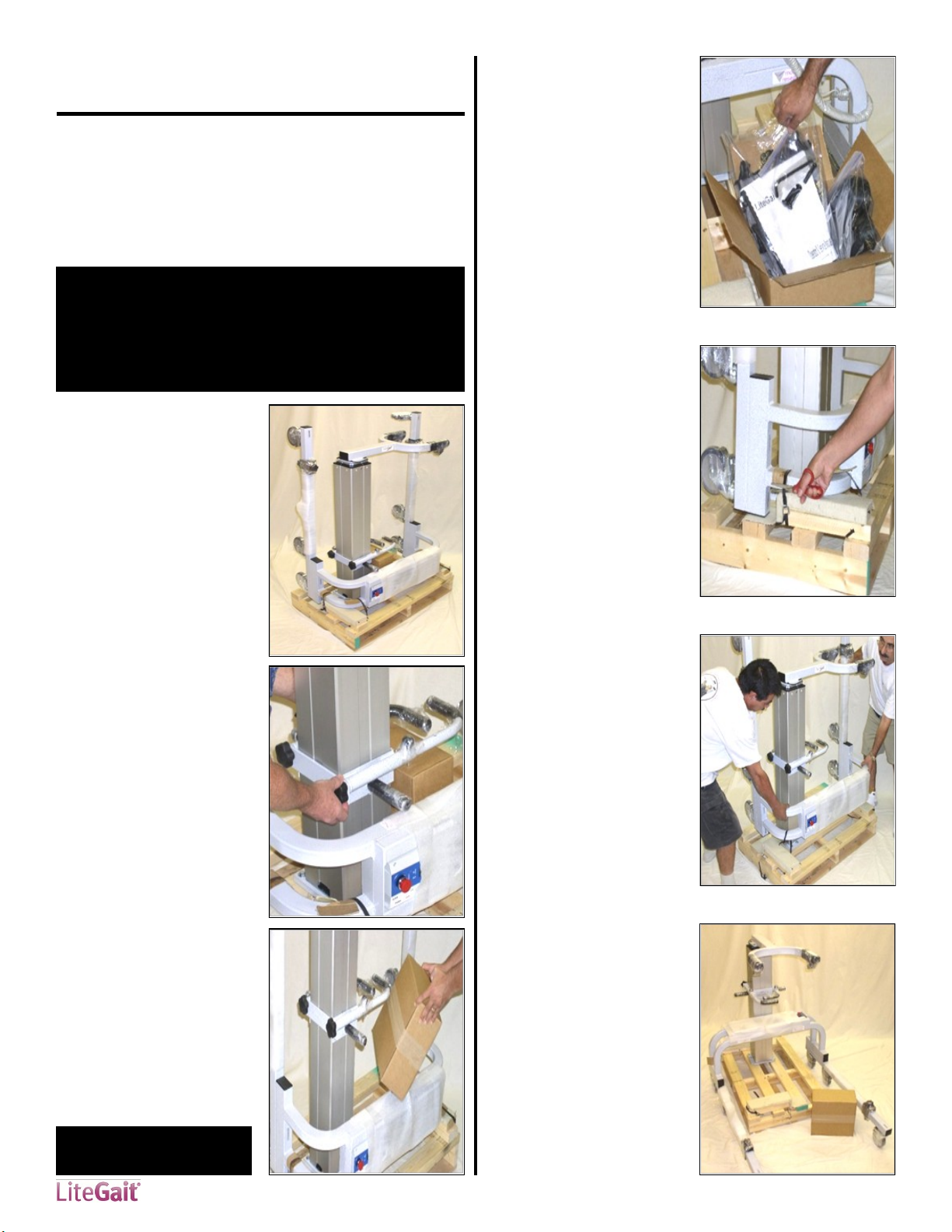
LiteGait® 300 Assembly............................................................................................... 10
LiteGait® 400/500 Assembly ....................................................................................... 10
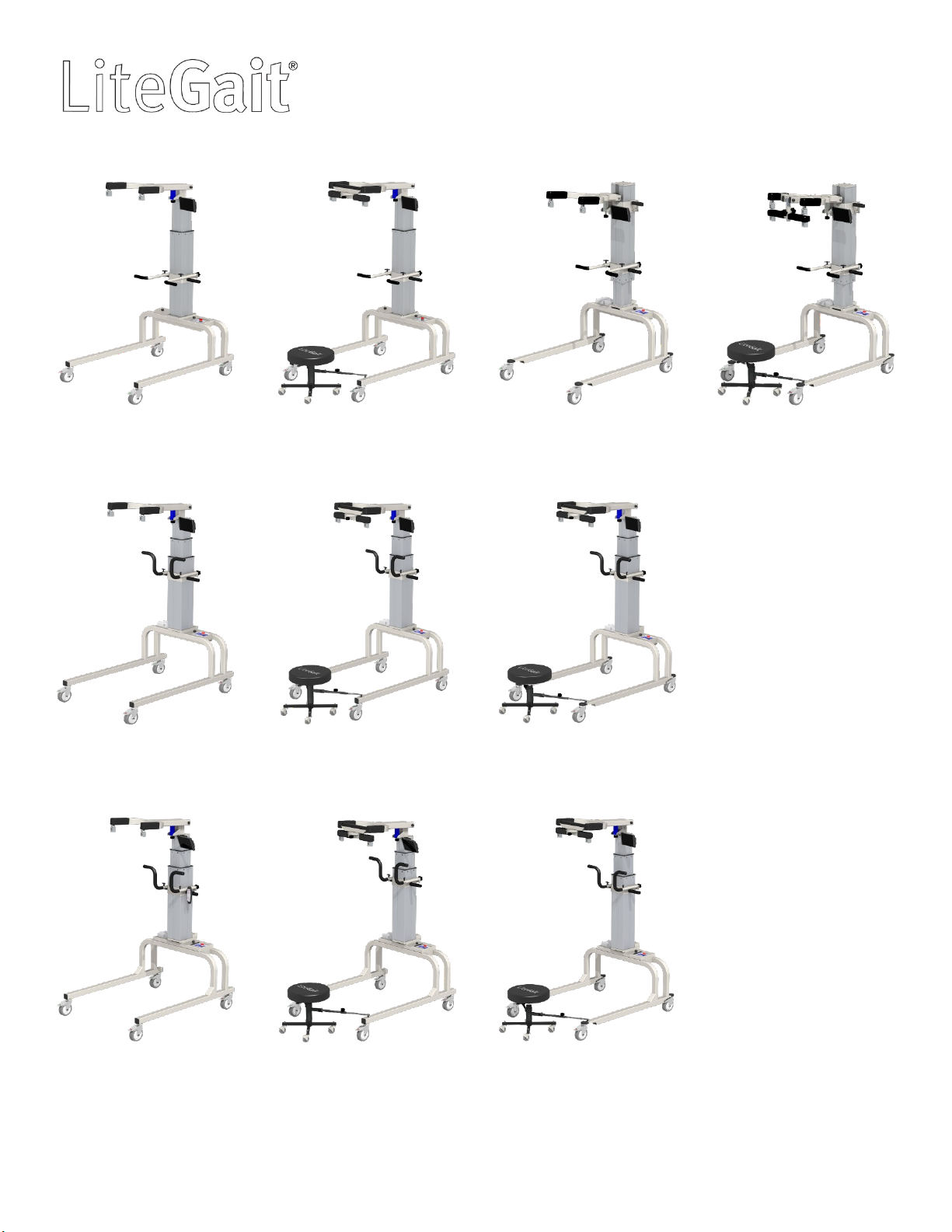
LiteGait® Diagram....................................................................................................... 16
About Your Unit.......................................................................................................... 16
USING Your LiteGait® .................................................................................................. 17
I. Control Unit .......................................................................................................... 17
II. Charging LiteGait®................................................................................................ 17
III. Charging LiteGait® I 300 Standard/Deluxe ........................................................... 17
IV How to Adjust Yoke Height................................................................................... 18
V. FlexAble ............................................................................................................... 18
VI. FreeDome........................................................................................................... 18
V. Adjusting Handlebars ........................................................................................... 19
VI. Base and Casters................................................................................................. 19
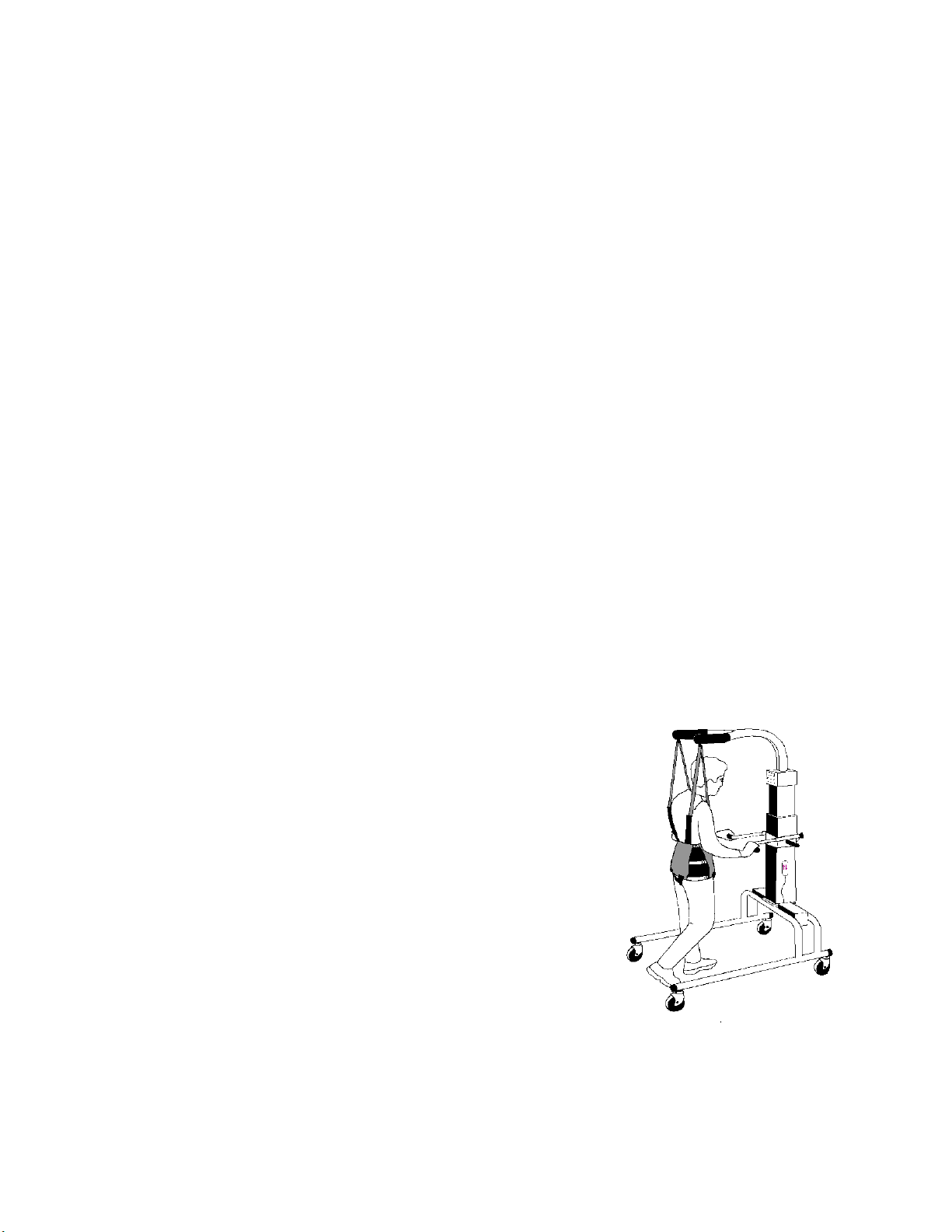
VII. Harness Application ........................................................................................... 20
Unit Care and Maintenance ....................................................................................... 25
Troubleshooting ......................................................................................................... 28
Parts List .................................................................................................................... 30
Appendix A. FreeDome ............................................................................................. 33
Appendix B. BiSym ..................................................................................................... 36
Resource Directory ..................................................................................................... 43

10 www.LiteGait.com
1-800-332-9255
LiteGait® 300Assembly
Tools Required:
Scissors
1/2 inch socket or open-end wrench
5/16 inch Allen wrench (provided)
LiteGait® I Assembly Instructions:
Read below & follow pictures.
NOTE: Two people are required for safe assembly.
NOTE: Your LiteGait® may look different than the following
images.
1.) After removing the
shipping carton, examine
the LiteGait® and report any
damage to immediately to
Mobility Research Service &
Parts Department at 800-332
-9255 EXT 7104.
3.) Open the cardboard box
containing the following:
Rechargeable Battery
Battery Charger
Harness & Harness
Accessories
BiSym Tablet (Optional)
2.) Loosen handle bar knobs
and raise handle bars to
allow access to the enclosed
cardboard box.
NOTE: If you have any questions during installation, please
contact Mobility Research Service Dept. for assistance.
CAUTION: DO NOT USE
UTILITY KNIFE TO OPEN BOX
4.) Inspect contents of
harness and accessories box
for damage.
5.) Carefully cut all black
plastic straps securing base
to pallet.
6.) Using both people,
remove base from pallet.
7.) Position base over pallet
with actuator near base as
pictured.

11 www.LiteGait.com
1-800-332-9255
8) Cut and remove plastic
wrap from base
compartment
13.) Using two people lift
actuator up onto base such
that the yoke and handle
bars are facing the same
direction as the legs of the
base.
14.) Route actuator cord
between through hole of
base plate before attaching
actuator to base. Cord
should be routed through
the hole in the base of base
plate.
11.) Before attaching the post
to the base, the LiteGait®
yoke and legs should be
oriented in the same direction
as shown in the picture to the
right.
Yoke
Legs
9.) Remove hand switch and
control box from inside base
compartment and set aside
for installation of actuator
10.) Prepare base for
installation of actuator.
Remove four steel bolts from
base using Allen wrench in
small box. Please note bolt
pattern for base plate may
vary.
11.) Remove screws securing
actuator to pallet.
12.) Lower handlebars on
actuator and tighten knobs
before lifting.

12 www.LiteGait.com
1-800-332-9255
21.) These units utilize a
charging cord connected to
the control box within the
LiteGait® base. To charge
connect charging cord to
outlet.
20.) Turn control box on by
rotating the red button
clockwise. The battery
capacity display should
display four solid black bars
indicating a full charge. If the
display does not show any
solid black bars check battery
connection.
15.) Insert bolts and hand
tighten. Make sure while one
person is inserting bolts, the
other is holding the actuator.
Tighten the bolts until snug
using the Allen wrench.
CAUTION: DO NOT over
tighten the bolts.
15.) Tighten the bolts until
snug using the Allen wrench.
23.) Verify the connection of
the power system to the
actuator by pressing the up
and down buttons on the
hand switch.
24.) Carefully remove all
shrink wrap from LiteGait®.
Contact Mobility Research at 1-800-332-9255 Option 1 For
assistance.
15.) Route actuator cord
between through hole of
base plate before attaching
actuator to base. Cord
should be routed through
the hole in the base of base
plate.
16.) Raise actuator column
onto base plate to attach
post to base. Avoid pinching
of the actuator cord between
the actuator plate and base
plate.

13 www.LiteGait.com
1-800-332-9255
LiteGait® 400/500 Assembly
Tools Required:
Scissors
1/2 inch socket or open-end wrench
5/16 inch Allen wrench (provided)
LiteGait® I Assembly Instructions:
Read below & follow pictures.
NOTE: Two people are required for safe assembly.
NOTE: Your LiteGait® may look different than the following
images.
1.) After removing the
shipping carton, examine
the LiteGait® and report any
damage to immediately to
Mobility Research Service &
Parts Department at 800-332
-9255 EXT 7104.
3.) Open the cardboard box
containing the following:
Rechargeable Battery
Battery Charger
Harness & Harness
Accessories
BiSym Tablet (Optional)
2.) Loosen handle bar knobs
and raise handle bars to
allow access to the enclosed
cardboard box.
NOTE: If you have any questions during installation, please
contact Mobility Research Service Dept. for assistance.
CAUTION: DO NOT USE
UTILITY KNIFE TO OPEN BOX
4.) Inspect contents of
harness and accessories box
for damage.
5.) Carefully cut all black
plastic straps securing base
to pallet.
6.) Using both people,
remove base from pallet.
7.) Position base over pallet
with actuator near base as
pictured.

14 www.LiteGait.com
1-800-332-9255
10.) Prepare base for
installation of actuator.
Remove four steel bolts from
base using Allen wrench in
small box. Please note bolt
pattern for base plate may
vary.
9.) Remove hand switch from
inside base compartment
and set aside for installation
of actuator
14.) Route actuator cord
between base and actuator
plate before attaching
actuator to base. Cord
should rest in slot of back of
actuator plate.
8) Cut and remove plastic
wrap from base
compartment
13.) Using two people lift
actuator up onto base such
that the yoke and handle
bars are facing the same
direction as the legs of the
base.
11.) Before attaching the post
to the base, the LiteGait®
yoke and legs should be
oriented in the same direction
as shown in the picture to the
right.
Yoke
Legs
11.) Remove screws securing
actuator to pallet.
12.) Lower handlebars on
actuator and tighten knobs
before lifting.

15 www.LiteGait.com
1-800-332-9255
16.) Insert loose actuator
cord wires into compartment
below actuator plate.
18.) Position cover over
actuator cable and bolts
securing actuator plate to
base. Cover is secured using
magnets. A slight gap may be
present between actuator
and cover OR base and
cover.
(ONLY APPLICABLE TO
SELECT LITEGAIT MODELS)
19.) Locate battery and
position in base.
NOTE: Battery requires
charging of once per week
overnight regardless of use.
22.) LiteGait® is powered by
a rechargeable battery. To
charge remove battery from
base and connect charger to
battery.
23.) Verify the connection of
the power system to the
actuator by pressing the up
and down buttons on the
hand switch.
24.) Carefully remove all
shrink wrap from LiteGait®.
Contact Mobility Research at 1-800-332-9255 Option 1 For
assistance.
15.) Insert bolts and hand
tighten. Make sure while one
person is inserting bolts, the
other is holding the actuator.
Tighten the bolts until snug
using the Allen wrench.
CAUTION: DO NOT over
tighten the bolts.
19.) Position actuator cord
cover, located in the
cardboard box, over actuator
cable and bolts securing
actuator plate to base. Cover
is secured using magnets.

16 www.LiteGait.com
1-800-332-9255
LiteGait® Diagram
1. Yoke Assembly
2. Buckle Assembly
3. FlexAble
4. Handle Bar Assembly
5. Rechargeable Battery
6. Total Locking Casters
7. Directional Locking Casters
8. Base/Frame
9. Control Unit
10. Actuator
11. BiSym
12. FreeDome Yoke - Removable (OPTIONAL)
13. Integrated FreeDome Yoke (OPTIONAL)
14. Gaiter Stool (OPTIONAL)
1
2
3
5
6 8
10
7
9
4
13
About Your LiteGait®
NOTE: Your LiteGait® may look different than image above
YOKE ASSEMBLY: Support Arm with four female buckles at
the ends and is attached to the actuator with a flat plate
secured by four bolts.
OVERHEAD STRAPS: Four 44” long adjustable straps with male
connectors at one end and padded female buckles at the
opposite end. The male connectors attach to the yoke buckles
and the female buckles attach to the harness providing
postural support for the patient.
HARNESS/GROIN PIECE: Adjustable wrap with a buckle closure
in the front and three adjustable straps on each side. The four
male connectors at the top of the harness that attach into the
female buckles of the overhead straps. The four female
buckles at the bottom of the harness allow for the connection
of the groin piece. The H-shaped stitching on the groin piece
denotes the top (or body side) of the piece.
ACTUATOR: The mechanism that raises and lowers the yoke.
The actuator consists of a concentric expanding and retracting
square tower that houses the DC motors, gearing and the
screw mechanism. It also provides the structural base to
which the adjustable handlebars are attached.
CONTROL UNIT: Power system interface for the battery,
handheld switch and actuator control.
HANDLEBARS: Unit has two adjustable handlebars. The
handlebars are attached to the unit using two knobs. NOTE:
Over tightening the knobs may cause damage.
BASE: Two horizontal bars connected by two U-shaped tubes.
The base moves freely over ground or can be locked into place
during use over a treadmill. However the unit must be locked
into place at all other times.
CASTERS: Four casters are attached to the base. The two
casters on the left side are total locking and the two casters on
the right are directional locking. Be certain to lock both casters
brakes when using the unit over a treadmill or when
connecting the patient to the unit. WARNING: NEVER leave
patient unattended in the unit.
BISYM (OPTIONAL): Provides a display of the pounds/
percentage of support provided by each arm of the yoke. The
buckle assemblies are mounted to sensors that measure the
patient load. The sensor values are processed and displayed
using the BiSym T instrumentation.
FREEDOME—REMOVEABLE (OPTIONAL): FreeDome that
allows for rotation of patient while supported by LiteGait®.
Removable from main FlexAble yoke. Does not allow for use
with the BiSym Instrumentation.
INTEGRATED FREEDOME (OPTIONAL): Integrated FreeDome
that allows for rotation of patient while supported by
LiteGait®. Allows for use with the BiSym instrumentation.
Gaiter Stool (OPTIONAL): Adjustable stool for therapist to help
facilitate lower extremity cueing. Attaches to the LiteGait.
12
14
11

17 www.LiteGait.com
1-800-332-9255
Using Your LiteGait®
I. Control Unit
Control Unit is the part of the LiteGait®that controls
the adjustment of the actuator. The control STOP and
Plug Icons box consists of the following features.
Red ON/OFF Button
Battery Charge Indicator
Emergency Down Button
Red ON/OFF Button
The emergency ON/OFF Button is the ON/OFF switch
for the LiteGait. To turn the device on, rotate the red
button clockwise and it should pop outward. To turn
the device off press the red button down. The device
also automatically turns off when connected to a
power outlet
ON OFF
Battery Charge Indicator
The Battery Charge Indicator shows the idle charge on
the battery while the device is on. The indicator
displays the charge in 25% increments. 4 solid black
bars indicates a full charge on the battery. A plug icon
appears in the 50% capacity bar when charge is down
to 25%. The LiteGait®should be charged when the plug
icon appears. When the battery charge is 0% the
display will show a STOP and a Plug icon, this indicates
that the device needs to be charged as soon as
possible. When the device is turned OFF or is
connected to an outlet the display indicates the STOP
and Plug Icons.
100% Charge 25% Charge 0% Charge
II. Charging LiteGait
LiteGait® is equipped with a 24 volt battery pack that
needs to be charged on a weekly schedule.
NOTE: LiteGait®Battery Should be charged overnight AT
LEAST ONCE PER WEEK regardless of use.
1. Disconnect LiteGait®
Smart PowerTM Battery
from LiteGait® Base
2. Plug charger into
LiteGait® Smart PowerTM
Battery
3. Red LED indicates
battery is charging. Green
LED battery is not
connected or fully
charged.
3. After charging battery
for 6-8 hours or overnight,
connect battery to
LiteGait® for use.
III. Charging LiteGait®- 300 Series
LiteGait® is equipped with a 24 volt battery pack that
needs to be charged on a weekly schedule.
1. Remove cover to
battery compartment
from LiteGait® Base.
4. LiteGait® only operates
on battery power and will
not raise or lower while
connected to the power
outlet.
2. Remove charging cord
from LiteGait® Base and
connect to power outlet.
3. Green “ON” LED shows
LiteGait®is connected to
outlet. Yellow “CHARGE”
shows battery is charging.

18 www.LiteGait.com
1-800-332-9255
V. FlexAble
FlexAble allows for the rigid yoke to become position
flexible, with up to 5 inches of travel. Thus, you can
maintain the rigid yoke position or make it flexible giving
the patient the option to experience more of their
balance and weight bearing at their own discretion.
Flexible Support
Loosen the star knob on the bottom of the FlexAble. The
amount of deflection can be varied by the amount the
knob is loosened
Rigid Support
Tighten the star knob completely on the bottom of the
FlexAble
IV. How to Adjust Yoke Height
The LiteGait®powered actuator column is raised and
lowered by a hand switch with two up and two down
arrows.
Raising the Yoke
Verify that LiteGait®has clearance above the yoke.
Depress the button with the up arrow on the hand
switch. Release the button when the yoke is at the
desired height.
Lowering the Yoke
Verify that LiteGait®has clearance below the yoke.
Depress the button with the down arrow on the hand
switch. Release the button when the yoke lowers to
the desired height.
Lowered Raised
Emergency Lowering of Yoke
If the down buttons fail to lower during normal use due
to a low battery. There is an auxiliary down button that
can be pressed to lower the device. Using a pen tip or
small screwdriver, press the black emergency down
button, this lowers one of the two columns of the
LiteGait® when pressed.
CAUTION: Using the Emergency Down Button may damage
battery for future use. Use only in case of emergency.
BiSym Integrated FreeDome Yoke with FlexAble
VI. Integrated FreeDome - OPTIONAL
FreeDome allows for rotation of the patient while being
supported by the LiteGait. Removable FreeDome
instructions are found in APPENDIX A on page 31. To
rotate the FreeDome, loosen the knob on the bottom of
rotational assembly. To lock the FreeDome tighten the
knob until snug.
Loosen Knob to
rotate FreeDome
Tighten Knob to
lock FreeDome
Using Your LiteGait®
FlexAble Yoke

19 www.LiteGait.com
1-800-332-9255
Using Your LiteGait®
Adjusting Handle Bar Configuration
To adjust the configuration, perform the following steps.
Press the button on the quick release handle bar pin and
pull outward.
Adjust handle bar insert to desired length and
orientation.
Press the button on the quick release handle bar pin and
insert handle bar pin. The pin can be inserted vertically
and horizontally.
WARNING: LiteGait® Handlebars are designed to be used as a
balance aid while using the LiteGait. Excess loading of the
handlebars may damage handlebars. Avoid Having patients
lift their weigh using the handlebars.
VII. Adjusting Handlebars
Raising and Lowering the Handle Bar
Loosen each knob in equal portions. The knobs should
only need to be turned once to free the handlebars.
Once the knobs are loosened slide the handlebars to the
desired height. Hand tighten both knobs equally. The
knobs should only need to be tightened one rotation.
VIII. Base and Casters
LiteGait® is equipped with four casters. There are two
total locking casters and two directional lock casters.
Each leg has one type of casters, the total locking are
mounted on the left leg the directional locking are
mounted on the right leg.
Directional Lock
Total Lock
Total Locking Casters
Total locking casters are indicated by a red
sticker on the locking lever. To lock the total locking
casters, press the tab until the brake snaps into place.
The caster will lock the swivel of the caster and
rotation of the wheel. Locking all four casters will
make the device stationary.
Directional Locking Casters
Directional Lock casters are indicated by a green
sticker in the locking lever. To lock the directional
locking casters, press the tab and align the caster with
the frame. Once aligned this locks the swivel of the
casters and is beneficial for walking in a straight path
or placing LiteGait® over a treadmill. Once the unit is
positioned over a treadmill, all four caster brakes need
to be locked
NOTE: While locking the caster prevents rolling of the unit, it
DOES NOT prevent the unit from sliding on a sloped, slippery
floor. The unit should only be used on a flat floor away from
stairs or ramps. NEVER leave a patient unattended in the
unit.
BRAKE
STEER
Directional Locking Casters with Treadmill
Position LiteGait® near the treadmill (or where you
wish the patient to begin walking).
Roll LiteGait® towards the front of the treadmill, until
the casters line up parallel to the treadmill (or parallel
to the path the patient will follow—a hallway for
example).
Press the directional locks to lock swivel of casters
LiteGait® can now be easily rolled back and forth over
the treadmill or on a straight path in the therapy room
or hallway.

20 www.LiteGait.com
1-800-332-9255
Using Your LiteGait®
IX. Harness Application
The harness was designed to support a patient in an upright position, allowing for full hip extension. This upright
posture plays a critical role in the effectiveness of the gait therapy performed with partial weight bearing.
Harness Components
The front of the harness wrap refers to the point at which the two ends of the harness meet. The harness can be worn
with the closure either in the front or in the back. There are four buckles on the top and bottom of the harness wrap.
The four top buckles extend beyond the harness from the top seam and attach to the LiteGait® overhead straps. The
bottom four buckles attach to the groin piece and do not extend past the bottom seam of the harness.
Preparing Harness for Application
1. Pick the appropriate harness (based on patient’s girth) and groin piece (based on patient’s anterior-posterior
diameter) for the patient.
2. Adjust the groin strap buckles so there is symmetry in the straps-- equal strap length available on both ends of the
padded groin piece and equal from side to side.
3. Attach the groin piece to the back of the harness.
NOTE: The side of the groin piece with the H‐outline stitching (most
padded) will go against the patient’s body.
Front
Overhead Straps
Groin Pieces
Girth Adjustment
Estimating the Starting Size
Half the Girth Test
1. Estimate the harness girth before placing on the patient by folding the unbuckled
harness in half so that the ends meet.
2. Hold the folded harness in front of the patients torso to estimate the width from one
side of the body to the other.
3. Tighten or loosen the three rows of side straps on each side of the harness to estimated
girth.
Symmetry Test
1. With the unbuckled harness folded in half, check the alignment of the top buckles (the
ones that attach to the overhead straps of LiteGait). The buckles should line up / be
adjacent to each other . If not adjacent , make small adjustment to side straps as
needed to regain symmetry. Each side strap should be similarly lengthened to achieve
symmetry.
Other manuals for 300 Series
1
This manual suits for next models
13
Table of contents
Other LiteGait Medical Equipment manuals
Popular Medical Equipment manuals by other brands

Iridex
Iridex OcuLight Symphony Operator's manual

Getinge
Getinge Maquet PowerLED II Instructions for use

Drive Medical
Drive Medical Bed Assist Handle installation instructions

Reison
Reison 10-398 user manual

Seating Matters
Seating Matters Milano instruction manual

Pathy Medical
Pathy Medical Light Jacket PM-LJ100 Instructions for use