LiteGait HugN-Go 350 User manual

Assembly Instructions
HugN
HugN
HugN-
-
-Go 350
Go 350
Go 350
LiteGait® is a Registered Trademark of Mobility Research, Inc.
HugN-Go 350
To Do:
1. Assembly of HugN-Go - following assembly instructions.
2. Review complete user manual from LiteGait® Flash Drive or LiteGait.com Website.
3. Complete introductory Orientation Service Check phone call.
Call 800-332-9255 Ext 7100 for scheduling service check call.

IMPORTANT SAFETY INSTRUCTIONS
HugN-Go 350
Maximum
Patient Weight
350 lbs
Use only under the direct supervision of a health care professional or caregiver
Brakes should remain in the locked position at all times until transfer from one location to another
is initiated.
Operate on smooth and level surfaces ONLY.
READ USER MANUAL BEFORE USING LiteGait®
***WARNING***
Resource Directory
Phone/Fax Website: Email Directory
Phone :
800.332.WALK (9255)
Toll free in U.S. and Canada
Fax:
480-829-0737
LiteGait.com
LiteGait.org
LiteGait® is a Registered Trademark of mobility research, Inc. (2015 US)
P.O. Box 3141, Tempe, AZ 85280, Tel: 800-332-9255, Fax:480-829-0737, Email: CustomerSupport@LiteGait.com, www.LiteGait.com

1
2
3
4
6
12
10
8
5
9
7
Main Assembly
Turn Station Assembly 13
15
14
16
1. Lifting Arm
2. Turn Station Assembly
3. Arm Supports
4. Battery / Charging Cord Compartment
5. Base Frame
6. Directional Locking casters
7. Handle Bars
8. Post
9. Actuator
10. Control Box
11. Total Locking Casters
13. Hand Switch
14. Adjustable Chest Pad
15. Adjustable Arm Support
16. Leg Strap Hook
17. Oxygen Tank Holder (OPTIONAL)
18. Arm Support Pad
19. Adjustable Hip Pads
20. Back Strap Buckle
21. Groin Strap Buckle
22. Hand Grip Adjustment Knob
23. Adjustable Hand Grip
24. Adjustable Hand Grip Knob
25. Adjustable Arm Support Knob
26. Arm Support Wrap
27. Spring Pin for Adjustable Hip Pad
23
18 22
*WARNING: Do not have patients sit on the back strap. Back strap is de-
signed to support lumber spine.
Unit Diagram
NOTE: Your HugN-Go may differ from images above
19
24
25
26
17
21
20

Assembly
Tools Required:
Scissors
1/2 inch socket or open-end wrench
5/16 inch Allen wrench (provided)
Read below & follow pictures.
NOTE: Two people are required for safe assembly.
NOTE: Your HugN-Go may look different than the following
images.
1.) Inspect shipment and note any
visual damage to box and/or crate
2.) Remove screw located at the
bottom of crate
3.) Lift off exterior box in order to
expose equipment
4.) Examine contents. Report any
damage to equipment immedi-
ately to Mobility Research Service
& Parts Department
6.) Open cardboard harness and
accessories box.
7.) Inspect contents of accessories
box for damage.
8.) Carefully cut all black plastic
straps securing base to pallet.
9.) Remove shrink wrap from all four
casters.
5.) Remove cardboard accessories
box.
10.) Using both people, remove
base from pallet.
NOTE: If you have any questions during installation, please
contact Mobility Research Service & Parts Department for
assistance.
CAUTION: DO NOT USE UTILITY KNIFE
TO OPEN BOX
Assembly Instructions:

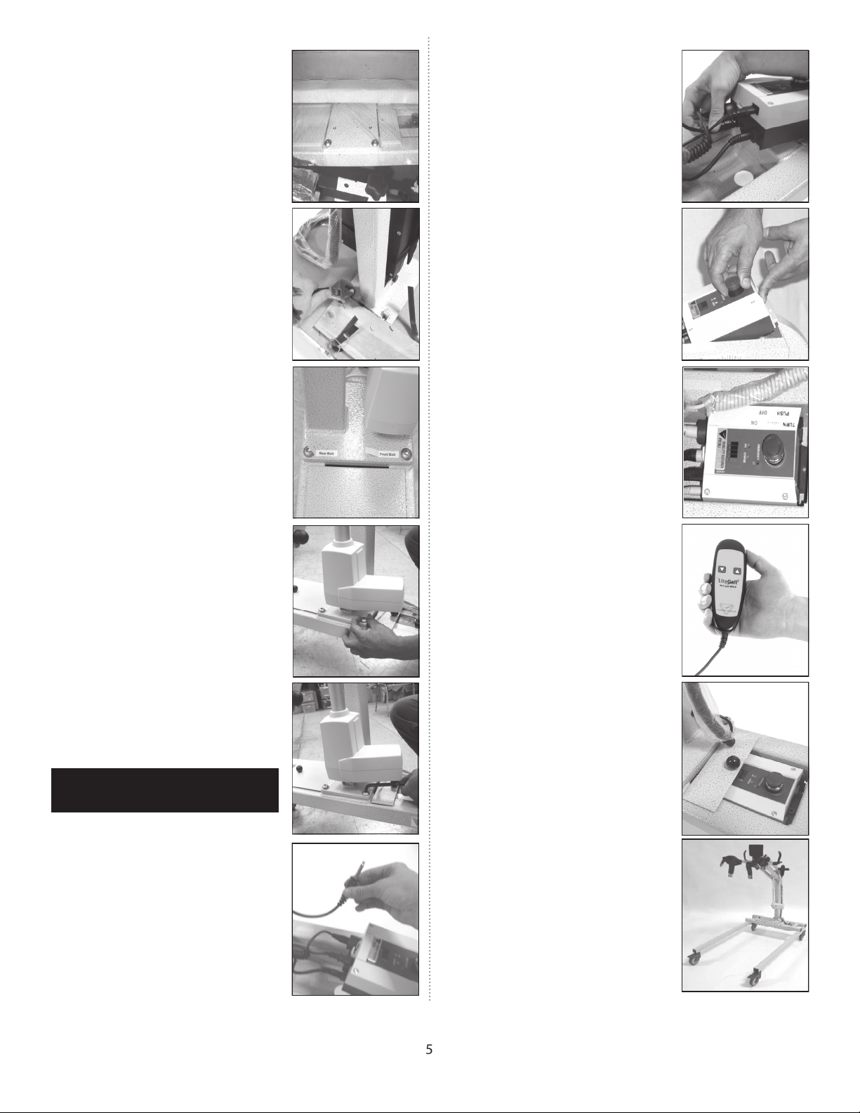
12) Free and remove lifting
mechanism (lifting arm, post, and
arm rest) with two people. While
attaching post, use once person to
support post while other inserts
bolts.
13.) Position the lifting mechanism
in the same direction of base legs.
Align holes on post plate with
base. Insert bolts marked Front
and Rear Bolts in corresponding
holes to secure post.
14.) Insert bolts labeled front and
rear in corresponding front and
rear holes on post plate. Hand-
tighten each of the four bolts to
create room for modified Allen
wrench.
15.) Tighten bolts with the Allen
wrench. Remove stickers labeled
front and rear after post is
attached.
11.) Cut and remove plastic wrap
from base.
16.) Locate actuator cord coming
out from the bottom of the post.
18.) Place control box back into
base.
24) The battery capacity display
should display four solid black bars
indicating a full charge. If the dis-
play does not show any solid black
bars check battery connection.
20.) Verify operation by moving
actuator up/down by pressing the
arrows on the hand switch. If hand
switch fails to operate the actua-
tor, check connections going into
the control box.
21.) Cove wires using the small
metal plate
17.) Plug the actuator cord into
the slot on the control box labeled
1. Slot 1 is located next to the larg-
est slot which is used for the hand
switch.
22.) Carefully remove
remaining packing material to
prepare for use. Device
assembly is complete!
.
CAUTION: DO NOT over tighten the
bolts.

Unit Care and Maintenance
HugN-Go Maintenance
Your HugN-Go has been specially designed to be durable and relatively maintenance free. The frame is constructed
from high strength steel, and has been painted with a special powder coat to resist rust and scratches.
Cleaning Frame:
Frequency * FOLLOW STANDARD FACILITY INFECTION CONTROL PROCEDURES.
Cleaning Agent DILUTED WINDEX TYPE CLEANING SOLUTION
Drying Method WIPE DRY WITH CLEAN CLOTH
Special Cleaning WD-40 CAN BE USED TO REMOVE DIRT OR OILY SPOTS.
Pad and Strap Maintenance
To clean the frame and straps, follow the instructions outlined in the table below.
Chest & Back Pads Leg Straps
Frequency Facility infection control guidelines
Cleaning Agent Facility infection control guidelines
Water Temperature WASH IN UP TO 176°F (80°C)
Drying Method HARNESSES SHOULD BE DRIED WITH LOW OR NO HEAT TUMBLE DRY
Special Cleaning WIPED WITH DISINFECTION WASH, PER FACILITY INFECTION CONTROL PRO-
CEDURES

To maintain the highest quality of function and safety, it is extremely important that you conduct regular maintenance
checks of your HugN-Go® unit and all of its parts. Please refer to the following checklist for an inspection guideline. If
you should have any questions concerning the functional status of any of the HugN-Go® parts, please contact the
Service & Parts Department immediately at Service@LiteGait.com. It is recommended that you inspect the HugN-Go®
unit and all of its parts every 6 months.
Check All Components Check List Recommended Replacement Schedule
Functionality
Cracks or Tears
Exposed or Frayed Wires
Loose/Rusted Bolts
Discoloration/Degradation
Battery 24-30 Months
Charger *
Hand Switch *
Chest Pad / Back Pad 18-24 Months
Groin Pieces 18-24 Months
Overhead Straps *
Casters *
Knobs *
Grips / Covers / Caps *
Base *
Actuator *
*Replace As Needed Based on Condition
Facility Name City State
First Last Title
Phone Fax Email
Model Serial Number
Please Send Copy of Completed Form Every 6 Months to Mobility Research Service & Parts Department
Mail: Mobility Research —Service & Parts Depart-
ment
P.O. Box 3141
Tempe, AZ 85280
Fax: 480-829-0737
Website: http://litegait.com/techsupport.html
Maintenance Contact Information
Please rate the function of each item as follows:
1 = POOR 2 = FAIR 3 = GOOD 4 = EXCELLENT.
A rating of FAIR (2) or POOR (1) indicates that that part should be immediately replaced to maintain the safe and
effective use of the equipment.
Unit Care and Maintenance

P.O. Box 3141, Tempe, AZ 85280, Tel: 800-332-9255, Fax:480-829-0737, Email: CustomerSupport@LiteGait.com, www.LiteGait.com
mobility research, Inc.
Domestic & International Use
Other manuals for HugN-Go 350
1
Table of contents
Other LiteGait Medical Equipment manuals