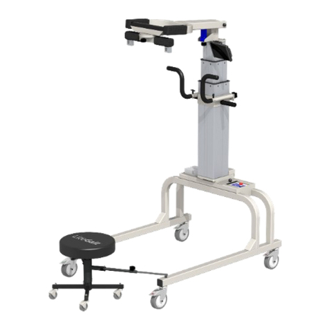
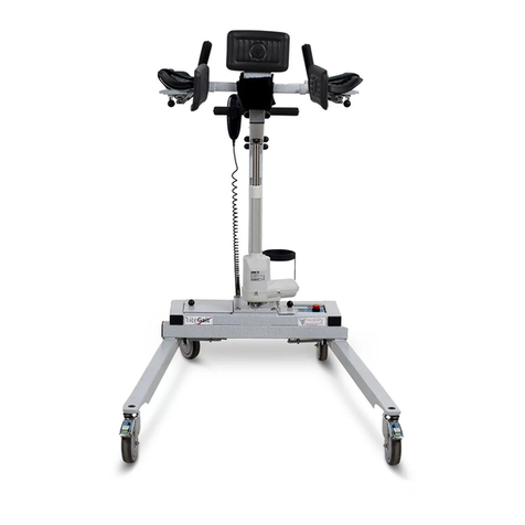
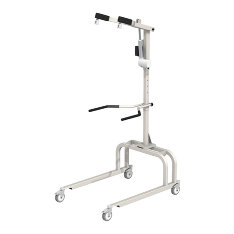
LiteGait Walkable User manual

Operator & Service Manual
/ LiteGait® Jr.
Jr.
Jr. / LiteGait® MX
MX
MXLiteGait®
LiteGait® is a Registered Trademark of Mobility Research, Inc.


3 www.LiteGait.com
1-800-332-9255
SERIAL
NUMBER
Serial Number of Your Device:
Note: Please keep your serial number in a safe and secure location. The serial number must be provided
when seeking service for your LiteGait® device. The serial number provides us access to technical
information regarding your device.


5 www.LiteGait.com
1-800-332-9255
IMPORTANT SAFETY INSTRUCTIONS
READ ALL INSTRUCTIONS BEFORE USING LiteGait®
***WARNING***
• Use only under the direct supervision of a healthcare professional
• Brakes should remain locked except when moving over ground
• Operate only on a smooth, level floor
• All four harness straps should be used at all times
• Examine device regularly for damage. Do NOT operate this device if it appears damaged
or inoperable
•If patient appears to be uncomfortable, faint, dizzy, short of breath, or ill while using the
device, stop session immediately.
• Charge the battery only with the factory authorized charging system.
•Do not tamper with the battery.
Maximum Height Maximum Patient Weight
LiteGait® WalkAble™ 75 5’0” 75 lbs
LiteGait® WalkAble™ 100 5’6” 100 lbs
LiteGait® 100MX 5’6” 100 lbs
LiteGait® 100MX w/I FreeDome 5’6” 100 lbs
LiteGait® 200MX 6’6” 200 lbs

6 www.LiteGait.com
1-800-332-9255

7 www.LiteGait.com
1-800-332-9255
LiteGait®
LiteGait® WalkAble 75
LiteGait® WalkAble 100
LiteGait® 100MX
LiteGait® 200 MX
LiteGait® 200MX
LiteGait® 100MX with
Integrated FreeDome
LiteGait® 100MX


Dear LiteGait® User,
CONGRATULATIONS on your recent purchase of LiteGait®, the most innovative gait and balance therapy
training system available today. As you know, LiteGait® can be used with a wide variety of patient
impairment levels and conditions. If you have questions about the possible uses of LiteGait® with
particular patients, or are in need of some ideas for ways to use LiteGait® more effectively, please do not
hesitate to contact us for information relating to your individual situation. Our website also offers valuable
information.
Like all quality therapy equipment, LiteGait® requires regular inspections. Enclosed is a check list for your
convenience. Please complete the checklist every 6 months to ensure the efficient, safe, and effective
operation of the LiteGait® unit. If you should find a problem with a LiteGait® part, please contact the
Service & Parts Department immediately. Here are some resources, which will be of help to you:
WEBSITE: www.LiteGait.com
USER FORUM : www.LiteGait.org
Sincerely,
Customer Service Department
Mobility Research


11 www.LiteGait.com
1-800-332-9255
Table of Contents
Unpacking and Assembly ...................................................................................12
Unit Diagram ......................................................................................................17
About Your Unit..................................................................................................17
USING Your LiteGait®..........................................................................................18
I. Yoke Adjustment...........................................................................................18
II. FlexAble.......................................................................................................18
III. Raising and Lowering MX Yoke - MX Only ...................................................18
IV. Charging MX Yoke - MX Only.......................................................................19
V. Adjusting Handle Bars..................................................................................21
VI. Base and Casters.........................................................................................21
VI. BiSym .........................................................................................................21
VII. Harness Application...................................................................................26
Training with LiteGait® .......................................................................................28
Unit Care and Maintenance ...............................................................................31
Troubleshooting ................................................................................................34
Parts List ............................................................................................................36
Resource Directory .............................................................................................39

12 www.LiteGait.com
1-800-332-9255
LiteGait® Assembly
Tools Required:
Scissors
1/2 inch socket or open-end wrench
5/16 inch Allen wrench (provided)
LiteGait®WalkAble/ Jr. / MX Assembly Instructions:
Read below & follow pictures.
NOTE: Two people are required for safe assembly.
NOTE: Your LiteGait® may look different than the following
images, but assembly Steps are the same.
1.) Inspect shipment and note any visual
damage to box and/or crate
2.) Remove screw located at the bottom
of crate
3.) Lift off exterior box in order to ex-
pose equipment
4.) Examine contents. Report any
damage to equipment immediately to
Mobility Research Service & Parts
Department
6.) Remove cardboard harness and
accessories box.
7.) Open cardboard harness and
accessories box.
8.) Inspect contents of harness and
accessories box for damage.
9.) Carefully cut all black plastic straps
securing base to pallet.
5.) Loosen handle bar knobs and raise
handle bars.
10.) Using both people, remove base
from pallet.
NOTE: If you have any questions during installation, please
contact Mobility Research Service & Parts Department for
CAUTION: DO NOT USE UTILITY KNIFE
TO OPEN BOX
NOTE: Your LiteGait® may look different than images above

13 www.LiteGait.com
1-800-332-9255
14.) To remove post from pallet use one
person to hold the post and yoke.
13.) Set base over pallet as pictured
with actuator near base.
12.) Prepare base for installation of
actuator. Remove four black steel bolts
from base using allen wrench in small
box.
15.) Locate bolts holding actuator to
pallet. Undo bolts with ½ inch socket or
wrench, loosen actuator from pallet
with one person holding the actuator
steady while loose.
11.) Position base over pallet with
actuator near base as pictured.
16.) Using two people lift the post onto
base.
18.) Insert bolts, hand tighten bolts
(ensure one person holds actuator
steady until secure). Tighten bolts using
5/16 inch Allen wrench until snug (do
not to over tighten).
19.) Verify operation by moving
actuator up/down by pressing the
arrows on the hand switch. If hand
switch fails to operate the actuator,
check connections at top of the
actuator.
20.) Carefully remove all shrink-wrap
from handle bars yoke and base
21.) Verify performance of each locking
and directional casters.
17.) Orient the actuator on the base
(the yoke arms and handlebars point in
the same direction as the base legs).
Line up the holes for bolts to be
inserted.
Feel free to call 1-800-332-9255 Extension 7104 for Mobility
Research Service & Parts during assembly.
CAUTION: DO NOT over tighten the
bolts.
NOTE: Your LiteGait® may look different than images above

14 www.LiteGait.com
1-800-332-9255
LG WalkAble Assembly
Tools Required:
Scissors
1/2 inch socket or open-end wrench
5/16 inch Allen wrench (provided)
LiteGait®KW Assembly Instructions:
Read below & follow pictures.
NOTE: Two people are required for safe assembly.
NOTE: Your LiteGait® may look different than the following
images, but assembly Steps are the same.
1.) Inspect shipment and note any visual
damage to box and/or crate
2.) Open carton carefully, using utility
knife to cut the tape that seals the box.
3.) Remove the post from the box and
carefully cut away package material.
4.) Open larger inside box containing the
yoke and handles bars. Carefully cut
away package material
6.) Remove the base from the box and
place on a level floor.
7.) Prepare remaining parts for
assembly by removing remaining
packaging material.
8.) Lock all four casters to make base
stationary and remove the bolts from
the top plate on the base.
9.) Lift the main post and align post
plate with holes on base plate.
5.) Remove and open soft goods. Soft
goods box should contain at least one
harness wrap, two groin pieces and four
overhead straps.
10.) Insert four bolts to attach post to
base plate. Tighten until snug using
7/32” Allen wrench (included).
NOTE: If you have any questions during installation, please
contact Mobility Research Service & Parts Department for
NOTE: Your LiteGait® may look different than images above

15 www.LiteGait.com
1-800-332-9255
14.) Tighten knobs to secure yoke in
position.
13.) Pull spring pin to lower the yoke on
the post.
12.) Attach post plate by tightening
knobs on the back of the handle bars to
secure in position.
11.) Loosen the knobs on handle bar
assembly to remove back plate and
position handle bars on post
Feel free to call 1-800-332-9255 Extension 7104 for Mobility
Research Support during this assembly.
NOTE: Your LiteGait® may look different than images above
Section intentionally left blank.

16 www.LiteGait.com
1-800-332-9255
This page intentionally left blank.

17 www.LiteGait.com
1-800-332-9255
LiteGait® Diagram
1. Yoke Assembly
2. Buckle Assembly
3. Control Box
4. Base/Frame
5. Total Locking Casters
6. Directional Locking Casters
7. Post Assembly
8. Handle Bar Assembly
9. Actuator
1
7
9
2
5
8
6
About Your LiteGait®
NOTE: Your LiteGait® may look different than image above
LiteGait® is comprised of several parts.
YOKE: Y-shaped support that has four female buckles at
the ends and is attached to the post. The height of the
yoke assembly is adjustable.
OVERHEAD STRAPS: Four adjustable straps with male
connectors at one end and padded female buckles at the
opposite end. The male connectors attach to the yoke
buckles and the female buckles attach to the harness
providing postural support for the patient.
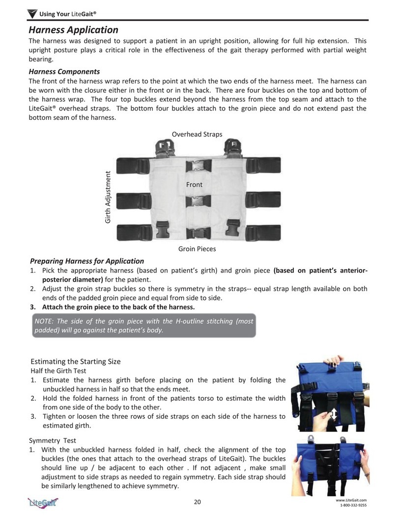
HARNESS/GROIN PIECE: Adjustable wrap with a buckle
closure in the front and three adjustable straps on each
side. The four male connectors at the top of the harness
that attach into the female buckles of the overhead
straps. The four female buckles at the bottom of the
harness allow for the connection of the groin piece. The
H-shaped stitching on the groin piece denotes the top (or
body side) of the piece.
ACTUATOR: The mechanism that raises and lowers the
yoke. The actuator consists of a linear adjusted screw
mechanism that is adjusted by a DC motor.
CONTROL UNIT: Junction box mounted on the actuator
for the battery power, handheld switch and contains
electrical safety protection circuitry. The battery pack
connects to this unit and is also located on the side of the
yoke assembly.
HANDLEBARS: Unit has two fixed position parallel
handlebars. The handle bars are attached to the unit
using two knobs.
BASE: Two horizontal bars connected by two U-shaped
tubes. The base moves freely over ground or can be
locked into place during use over a treadmill. However,
your unit must be locked into place at all other times.
CASTERS: Four casters are attached to the base. The
two casters on the left side are total locking and the two
casters on the right are directional locking. Be certain to
lock both caster brakes when using the unit over a
treadmill or when connecting the patient to the unit.
NOTE: Over tightening the knobs may cause damage.
WARNING: NEVER leave patient unattended in the unit.
3
4

18 www.LiteGait.com
1-800-332-9255
Using Your LiteGait®
I. Yoke Adjustment
The LiteGait® yoke is raised and lowered manually by
loosening the knobs securing yoke plate to the post.
Once the knobs are loose, the yoke can be raised or
lowered by pulling out the spring pin on the back of the
yoke. After adjusting the yoke to the desired height,
release spring pin and lock into the closest hole on the
back post. Tighten the knobs to secure the yoke once
in place. For the WalkAble 75, the yoke is secured by
tightening the lever knob on the front of the yoke.
Loosen Knobs Pull Out Spring Pin
NOTE: Your LiteGait® may look different than images above
II. FlexAble
FlexAble allows for the rigid yoke to become position
flexible, with up to 5 inches of travel. Thus, you can
maintain the rigid yoke position or make it flexible giving
the patient the option to experience more of their
balance and weight bearing at their own discretion.
Flexible Support
Loosen the star knob on the bottom of the FlexAble. The
amount of deflection can be varied by the amount the
knob is loosened
Rigid Support
Tighten the star knob completely on the bottom of the
FlexAble
NOTE: THE LiteGait YOKE & HARNESS PROVIDE FULL
SUPPORT to LiteGait USER WITH FlexAble FLEXIBLE or RIGID.
III. Raising and Lowering MX Yoke
- MX Only
The LiteGait® MX actuator is raised and lowered by a
hand switch with one up and one down arrow.
Raising the Yoke
Verify that LiteGait® has clearance above the yoke.
Depress the button with the up arrow on the hand
switch. Release the button when the yoke is at the
desired height.
Lowering the Yoke
Verify that LiteGait® has clearance below the yoke.
Depress the button with the down arrow on the hand
switch. Release the button when the yoke lowers to
the desired height.
Lowered Yoke Raised Yoke
NOTE: Your LiteGait® may look different than images above

19 www.LiteGait.com
1-800-332-9255
Using Your LiteGait®
Green LightRed Light
IV. Integrated FreeDome - Optional
FreeDome allows for rotation of the patient while
being supported by the LiteGait®. To rotate the
FreeDome, loosen the knob on the bottom of
rotational assembly. To lock the FreeDome tighten the
knob until snug.
Loosen knob to rotate
FreeDome.
Tighten knob to lock
FreeDome.
Low Battery Indicator Alarm
The LiteGait® unit emits an audible noise when the
charge of the battery is critically low and needs to be
recharged. If you experience audible noise, make sure to
charge promptly after use of the LiteGait®. The LiteGait®
will ONLY lift and lower approximately 2 to 3 more times
before shutting off. The LiteGait® should be charged
before running down to a point where you are unable to
lower a patient.
4. Align tabs on the bottom of the battery pack with the
side mount to reattach battery.
3. Plug the charger into the power outlet to charge the
battery. The battery should be charged at least once per
week overnight, regardless of use.
Note: Ensure the locking tab is locked in before releasing the
battery pack.
Charger
The LiteGait® battery is charged using a low current,
hospital guideline approved charger. The charger has an
indicator LED light that turns green when the charger is
plugged in and not connected to the LiteGait®. When the
battery is charging the LED turns red and then back to
green after the battery is fully charged.
Charging Battery Connected to Power outlet
Battery Charged
IV. Charging LiteGait
1. If the battery looks like this image, remove battery
pack from side of LiteGait® by lifting the locking tab and
pulling off the battery. If your battery does not look like
this, skip to the next page.
2. Locate battery charger and insert barrel plug into port
on battery pack. Then connect charger to outlet.

20 www.LiteGait.com
1-800-332-9255
Using Your LiteGait®
LiteGait is equipped with a 24 volt battery pack that needs to
be charged at least once per week overnight. Follow instruc-
tions below if you battery looks like this image.
Charging Procedure
1. Insert the charger plug into the port on the actuator top.
2. Plug the charger into the appropriate 110-volt or 220-volt
wall outlet.
3. Leave LiteGait on charger for 6-8 hours or overnight once
per week.
4. After charging LiteGait unplug the charger from the WALL
OUTLET AND LiteGait.
Note: Leaving a charger connected to the LiteGait while dis-
connected to the wall outlet device decreases the battery life
of the LiteGait battery.
Note: Leaving a charger connected to the LiteGait while dis-
connected to the wall outlet device decreases the battery life
of the LiteGait battery.
Low Battery Indicator Alarm
LiteGait emits an audible noise when the battery charge is low.
LiteGait will ONLY lift and lower approximately 2 to 3 more
times before shutting off. The charger LED light turns green
when the charger is plugged in and not connected to the
LiteGait. When the battery is charging the LED turns red and
then back to green after the battery is fully charged.
Green Light
The charger is plugged into
the socket (if the battery is
disconnected).
The battery is fully charged
(If the battery is connected
and the charger is plugged
into the socket
Red Light
The battery is being
charged by the charger.
This manual suits for next models
6
Table of contents
Other LiteGait Medical Equipment manuals
Popular Medical Equipment manuals by other brands

Invacare
Invacare Cadiz Series user manual

Detax
Detax addition ultra Instructions for use

Huvitz
Huvitz HRK-9000A Service manual

Siemens
Siemens PELTON & CRANE Light Fantastic II installation instructions

PARAMOUNT BED
PARAMOUNT BED PY-700 Series instruction manual

Ossur
Ossur Iceross Seal-In X Seal Series Instructions for use