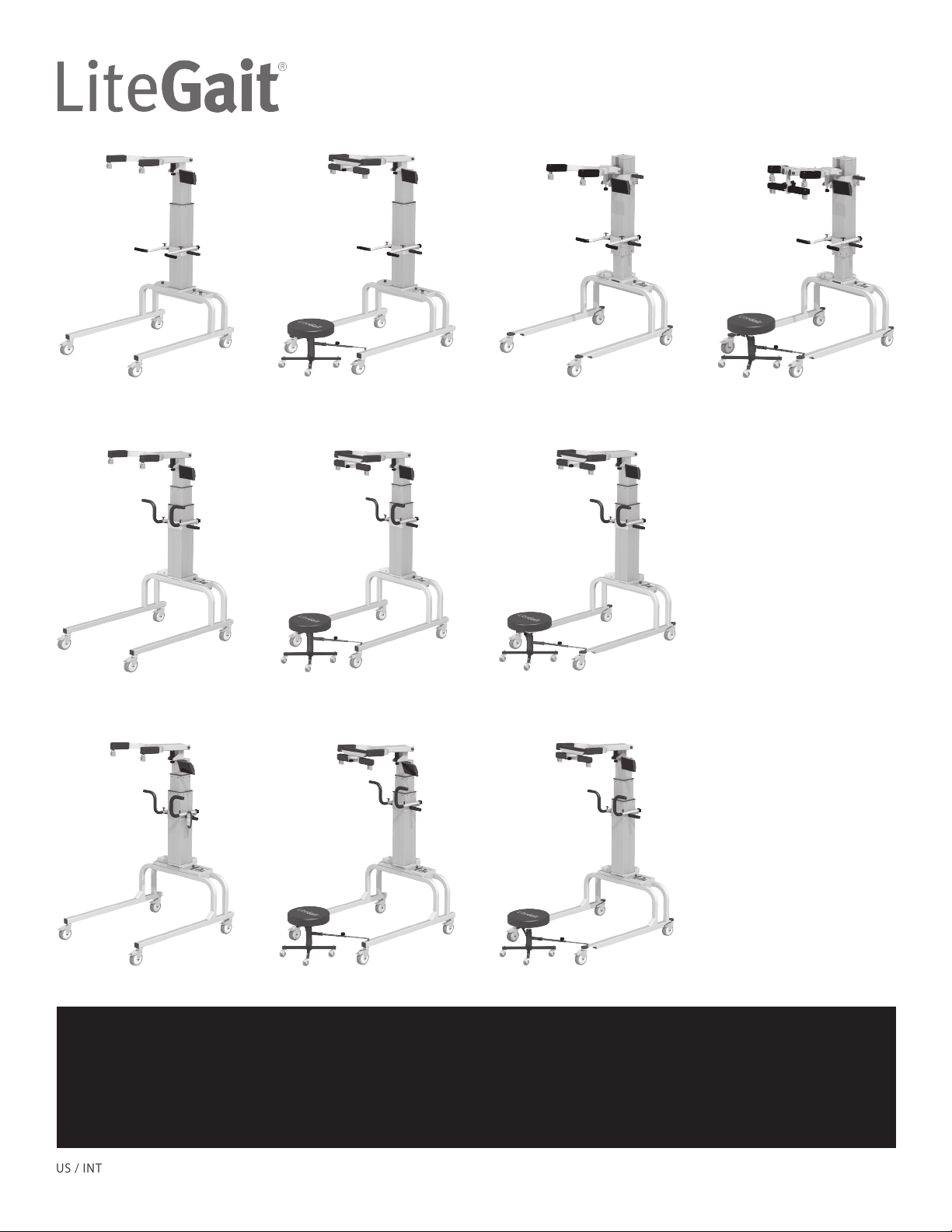
LiteGait 300 Series User manual

LiteGait® is a Registered Trademark of mobility research, Inc.
To Do:
1. Assembly LiteGait® following assembly instructions.
2. Review complete user manual from LiteGait® Flash Drive or LiteGait.com Website.
3. Complete introductory Orientation Service Check phone call.
Call 800-332-9255 option 1 for scheduling service check call.
300 Standard 300P Standard
400 Standard
500 Standard
300 Deluxe 300P Deluxe
400 Deluxe
500 Deluxe
400 Deluxe Tall
500 Deluxe Tall
400 Series
500 Series
300P Series300 Series
Assembly Instructions

IMPORTANT SAFETY INSTRUCTIONS
Maximum Unit Height Maximum Patient Weight
LiteGait® 300 Standard 7’ 11” 300 lbs
LiteGait® 300 Deluxe 7’ 11” 300 lbs
LiteGait® 300P Standard 7’ 6” 300 lbs
LiteGait® 300P Deluxe 7’ 6” 300 lbs
LiteGait® 400 Standard 7’ 9” 400 lbs
LiteGait® 400 Deluxe 7’ 9” 400 lbs
LiteGait® 400 Deluxe Tall 8’ 3” 400 lbs
LiteGait® 500 Standard 7’ 11” 500 lbs
LiteGait® 500 Deluxe 7’ 11” 500 lbs
LiteGait® 500 Deluxe Tall 8’ 5” 500 lbs
Use only under the direct supervision of a health care professional or caregiver
Brakes should remain in the locked position at all times until transfer from one location to another
is initiated.
Operate on smooth and level surfaces ONLY.
READ USER MANUAL BEFORE USING LiteGait®
***WARNING***
Resource Directory
Phone/Fax Website: Email Directory
Phone : 800.332.WALK (9255)
Toll free in U.S. and Canada
480-716-9648 ext 104
Fax:
480-829-0737
LiteGait.com
LiteGait® is a Registered Trademark of mobility research, Inc. (2017 US)
P.O. Box 3141, Tempe, AZ 85280, Tel: 800-332-9255, Fax:480-829-0737, Email: CustomerSupport@LiteGait.com, www.LiteGait.com

LiteGait® Diagram
1. Yoke Assembly
2. Buckle Assembly
3. FlexAble
4. Handlebar Assembly
5. Rechargeable Battery
6. Total Locking Casters
7. Actuator
8. Control Unit
9. Base/Frame
10. Directional Locking Casters
11. BiSym
12. FreeDome Yoke - Removable (OPTIONAL)
13. Integrated FreeDome Yoke (OPTIONAL)
14. Gaiter Stool (OPTIONAL)
1
2
3
5
6 9
7
10
8
4
13
NOTE: Your LiteGait® may look different than image above
12
14
11
About Your LiteGait®
YOKE ASSEMBLY: Support Arm with four female buckles at
the ends and is attached to the actuator with a flat plate
secured by four bolts.
OVERHEAD STRAPS: Four 44” long adjustable straps with male
connectors at one end and padded female buckles at the
opposite end. The male connectors attach to the yoke buckles
and the female buckles attach to the harness providing
postural support for the patient.
HARNESS/GROIN PIECE: Adjustable wrap with a buckle closure
in the front and three adjustable straps on each side. The four
male connectors at the top of the harness that attach into the
female buckles of the overhead straps. The four female
buckles at the bottom of the harness allow for the connection
of the groin piece. The H-shaped stitching on the groin piece
denotes the top (or body side) of the piece.
ACTUATOR: The mechanism that raises and lowers the yoke.
The actuator consists of a concentric expanding and retracting
square tower that houses the DC motors, gearing and the
screw mechanism. It also provides the structural base to
which the adjustable handlebars are attached.
CONTROL UNIT: Power system interface for the battery,
handheld switch and actuator control.
HANDLEBARS: Unit has two adjustable handlebars. The
handlebars are attached to the unit using two knobs. BASE:
Two horizontal bars connected by two U-shaped tubes. The
base moves freely over ground or can be locked into place
during use over a treadmill. However the unit must be locked
into place at all other times. NOTE: Over tightening the knobs
may cause damage.
CASTERS: Four casters are attached to the base. The two
casters on the left side are total locking and the two casters on
the right are directional locking. Be certain to lock both caster
brakes when using the unit over a treadmill or when
connecting the patient to the unit. WARNING: NEVER leave
patient unattended in the unit.
BISYM (OPTIONAL): Provides a display of the pounds/
percentage of support provided by each arm of the yoke. The
buckle assemblies are mounted to sensors that measure the
patient load. The sensor values are processed and displayed
using the BiSym instrumentation.
FREEDOME—REMOVEABLE (OPTIONAL): FreeDome that
allows for rotation of patient while supported by LiteGait®.
Removable from main FlexAble yoke. Does not allow for use
with the BiSym Instrumentation.
INTEGRATED FREEDOME (OPTIONAL): Integrated FreeDome
that allows for rotation of patient while supported by
LiteGait®. Allows for use with the BiSym instrumentation.
Gaiter Stool (OPTIONAL): Adjustable stool for therapist to help
facilitate lower extremity cueing. Attaches to the LiteGait.

LiteGait® Assembly
Tools Required:
Scissors
1/2 inch socket or open-end wrench
5/16 inch Allen wrench (provided)
LiteGait® I Assembly Instructions:
Read below & follow pictures.
NOTE: Two people are required for safe assembly.
NOTE: Your LiteGait® may look different than the following
images.
1.) After removing the
shipping carton, examine
the LiteGait® and report any
damage to immediately to
Mobility Research Service &
Parts Department at 800-332
-9255 EXT 7104.
3.) Open the cardboard box
containing the following:
Rechargeable Battery
Battery Charger
Harness & Harness
Accessories
BiSym (Optional)
2.) Loosen handlebar knobs
and raise handlebars to allow
access to the enclosed
cardboard box.
NOTE: If you have any questions during installation, please
contact Mobility Research Service Dept. for assistance.
CAUTION: DO NOT USE
UTILITY KNIFE TO OPEN BOX
4.) Inspect contents of
harness and accessories box
for damage.
5.) Carefully cut all black
plastic straps securing base
to pallet.
6.) Using two people, remove
base from pallet.
7.) Position base over pallet
with actuator near base as
pictured.

8) Cut and remove plastic
wrap from base
compartment.
9.) Remove hand switch from
inside base compartment
and set aside for installation
of actuator.
10.) Prepare base for
installation of actuator.
Remove four bolts from base
using Allen wrench in small
box.
12.) Remove screws securing
actuator to pallet.
13.) Lower handlebars on
actuator and tighten knobs
before lifting.
14.) Using two people lift
actuator up onto base such
that the yoke and handle
bars are facing the same
direction as the legs of the
base.
15.) Route actuator cord
between base and actuator
plate before attaching
actuator to base. Cord
should rest in slot on back of
actuator plate.
11.) Before attaching the post
to the base, the LiteGait®
yoke and legs should be
oriented in the same direction
as shown in the picture to the
right.
Yoke
Legs

18.) Insert loose actuator
cord wires into compartment
below actuator plate.
19.) Position actuator cord
cover located in the
cardboard box over actuator
cable and bolts securing
actuator plate to base. Cover
is secured using magnets.
20.) Expect a slight gap
between actuator and cover
OR base and cover when
installed properly.
21.) Locate battery and
position in base. NOTE: 300
S &D models DO NOT have
removable battery continue
to step 24.
22.) Turn control box on by
rotating the red button
clockwise. The battery
capacity display should
display four solid black bars
indicating a full charge. If the
display does not show any
solid black bars check battery
connection.
NOTE: Battery requires
charging of once per week
overnight regardless of use.
23.) LiteGait® is powered by
a rechargeable battery. To
charge, remove battery from
base and connect charger to
battery.
FlexAble
17.) If applicable, pivot the
yoke arm over the top of
the LiteGait® Post as shown
in the following images. The
yoke should be resting on
the FlexAble Cartridge
16.) Insert bolts and hand
tighten. Make sure while one
person is inserting bolts, the
other is holding the actuator.
Tighten the bolts until snug
using the Allen wrench.
CAUTION: DO NOT over
tighten the bolts.
Post

24.) 300 S &D models utilize
a charging cord connected to
the control box within the
LiteGait® base. To charge,
connect charging cord to
outlet.
25.) Verify the connection of
the power system to the
actuator by pressing the up
and down buttons on the
hand switch.
26.) Carefully remove all
shrink wrap from LiteGait®.
27.) Assembly Complete.
If you have questions during the assembly process, contact
the Mobility Research Service & Parts Department for
assistance.
SECTION INTENTIONALLY LEFT BLANK

P.O. Box 3141, Tempe, AZ 85280, Tel: 800-332-9255, Fax:480-829-0737, Email: CustomerSupport@LiteGait.com, www.LiteGait.com
mobility research, Inc.
Domestic & International Use
Other manuals for 300 Series
1
This manual suits for next models
13
Table of contents
Other LiteGait Medical Equipment manuals
Popular Medical Equipment manuals by other brands

Direct Supply
Direct Supply Panacea 3000 owner's manual

Candulor
Candulor CRS Set 10 Product information

Weinmann
Weinmann SOMNOcomfort 2e Description of the equipment and instructions for use

Ambu
Ambu aScope 5 Broncho 2.7/1.2 Instructions for use

NDS
NDS ConductOR user manual

Medit
Medit i500 installation guide

Winco
Winco 6530 Owner's operating and maintenance manual

medi
medi Spinomed instructions

BTL
BTL 1500 user manual

COOK Medical
COOK Medical Percutaneous Nephrostomy Set Instructions for use

DHG
DHG RoMedic StretcherBar 70200006 Instructions for use

NorthEast Monitoring
NorthEast Monitoring DR181 HOOK-UP GUIDE