General guideline for components
Capacitors: All values under 1nF should be ceramic disks or silver mica. From 1nF up to 1uF
should be SMF (Panasonic stacked metal film) or MKT (Metallized plastic polyester) and
values over 1uF use electrolyte caps 16V+ rated and watch out for polarity! If you plan on
using a charge pump than all components must be 35V or more.
Resistors: use 1% metal film for the best results.
Socket the IC’s. This way you can easily mod them or replace them if they break.
General building tips
Soldering this board can be very complicated for some people since the solder pads are very close
together. Use a magnifying glass to make the job easier. If you want to experiment with other diodes
than you could socket them instead of soldering them to the board. You’ll need a 20 SIL, break off
the sockets and solder them to the board.
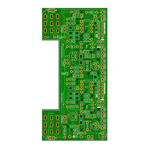
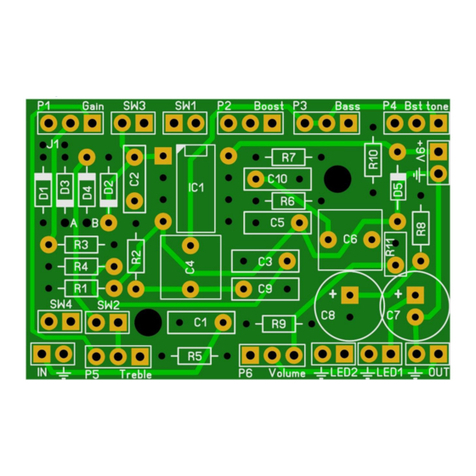
Start by soldering the resistors (but not yet VR7 and VR8) and then the diodes. All diodes need to be
soldered in an upright position except for D7.
Note: Diodes are fragile!! Do not expose them to heat for too long or they’ll break. Do not blow on
your solder in an attempt to cool it down. That will possibly result in a bad join that might corrode!
Solder the small ceramic capacitator C2 and C13 next.
Solder the 10n and 100n SMF/MKT capacitors. Next, solder the IC sockets, then the DIP switches
(only if you do not intend to use the external diode mod else leave out the dipswitches!) and lastly
solder the 1u SMF and electrolyte capacitors.
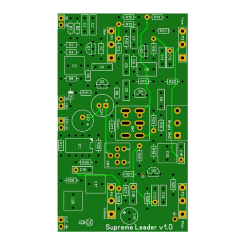
Finally solder the presence/treble boost trim pot VR7 and VR8. If you want to control the presence
externally than do not solder VR7 and VR8 but use a B50k pots. For your convenience I marked the
pinning on the PCB. The pots default setting is all the way to the right. To boost treble, turn the pots
to the left.
Place the IC and you are almost ready to rock.
Besides the components mentioned in the table on the page 3, you will need:
2 input jacks. 2 mono jacks if you are not going to use a battery but only the 9V adapter. 1
mono (for output) and 1 stereo jack (for input) if you will be using both a 9V battery and the
9V adapter.
2x 3PDT footswitch (9 pins). I also sell an easy off board circuit for true bypass.
2,1mm DC jack (isolated).
9v battery clip (optional).
22 gage stranded hook-up wire.
2 x LED (Green and Red or Orange and Red)
Hammond 1590BB case (or similar) in your favorite color. A Hammond 1590DD or
Hammond 1590XX will give you more room to build especially when using an external
presence pot.
