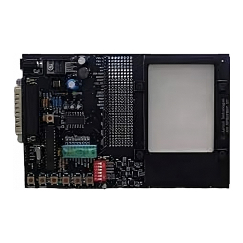
Littelfuse zilog ZMOTIONL400ZCOG User manual

ZMOTIONL400ZCOG
Z8F3224 ZMOTION
Development Kit
User Manual
UM029501-0321

Z8F3224 ZMOTION Development Kit
UM029501-0321 OVERVIEW
User Manual
ii
LIFE SUPPORT POLICY
ZILOG’S PRODUCTS ARE NOT AUTHORIZED FOR USE AS CRITICAL COMPO-
NENTS IN LIFE SUPPORT DEVICES OR SYSTEMS WITHOUT THE EXPRESS
PRIOR WRITTEN APPROVAL OF THE PRESIDENT AND GENERAL COUNSEL OF
ZILOG CORPORATION.
As used herein
Life support devices or systems are devices which (a) are intended for surgical implant into
the body, or (b) support or sustain life and whose failure to perform when properly used in
accordance with instructions for use provided in the labelling can be reasonably expected
to result in a significant injury to the user. A critical component is any component in a life
support device or system whose failure to perform can be reasonably expected to cause
the failure of the life support device or system or to affect its safety or effectiveness.
Document Disclaimer
©2021 Zilog, Inc. All rights reserved. Information in this publication concerning the devices,
applications, or technology described is intended to suggest possible uses and may be
superseded. ZILOG, INC. DOES NOT ASSUME LIABILITY FOR OR PROVIDE A
REPRESENTATION OF ACCURACY OF THE INFORMATION, DEVICES, OR
TECHNOLOGY DESCRIBED IN THIS DOCUMENT. ZILOG ALSO DOES NOT ASSUME
LIABILITY FOR INTELLECTUAL PROPERTY INFRINGEMENT RELATED IN ANY
MANNER TO USE OF INFORMATION, DEVICES, OR TECHNOLOGY DESCRIBED
HEREIN OR OTHERWISE. The information contained within this document has been
verified according to the general principles of electrical and mechanical engineering.
Z8 Encore!, Z8 Encore! XP, ZMOTIONTM, eZ80Acclaim! and ZNEO are trademarks or
registered trade- marks of Zilog, Inc. All other product or service names are the property of
their respective owners.
Warning: DO NOT USE THIS PRODUCT IN LIFE SUPPORT SYSTEMS.

Z8F3224 ZMOTION Development Kit
UM029501-0321 OVERVIEW
User Manual
1
Overview
Zilog’s Z8F3224 ZMOTION Development Kit provides a general-purpose platform for evaluating the
capabilities and operation of the ZMOTION Engine Library using the Z8F3224 Series of microcontrollers.
This kit is equipped with two Z8F3224 MCUs –one configured for Low Power operation and one
configured for Normal Power operation and comes complete with various lenses to test the ZMOTION
Engine Library for multiple applications.
Zilog’s ZMOTION Engine Library provides an integrated and flexible solution for Passive Infra-Red (PIR)-
based motion detection applications. The Software library is comprised of the PIR sensor signal
processing algorithms for motion detection, transient and noise detection, white light detection, and
several other motion-related functions to be integrated with the user’s application code.
An Application Programming Interface (API) allows the application code to configure, control, and monitor
the Library in real time. API configuration parameters allow the Engine operation to be optimized for the
particular lens and pyro electric sensor being used in the application. This allows the designer to create
their own application-specific software while taking advantage of Zilog’s ZMOTION Motion Detection
technology.
For more information about the operation of the ZMOTION Library, refer to ZMOTION Engine User
Manual (UM0275).
Kit Contents
The Z8F3224 ZMOTION Development Kit includes the components listed in the following table.
Item
Description
Quantity
1
Z8F3224 ZMOTION Development Board
1
2
Encore! Smart Cable or USB Smart Cable
1
3
Lenses:
ZCWM05GIV1, ZNCL11, ZNCL926, ZNCL10IL, ZNCL3B,
ZNCL10R, ZNCL10S
7
4
USB Cable - type A/B
1
Table 1. Kit Contents

Z8F3224 ZMOTION Development Kit
UM029501-0321 KIT CONTENTS
User Manual
2
Figure 1. ZMOTIONL400 Development Kit Contents

Z8F3224 ZMOTION Development Kit
UM029501-0321 KIT CONTENTS
User Manual
3
Figure 2. Development Board (top side)
Figure 3. Development Board (bottom side)

Z8F3224 ZMOTION Development Kit
UM029501-0321
User Manual
4
Lenses
The Development Kit includes seven lenses. Two mounting options are supported –Clip on and PCB
Mount. The following tTable 2 describes the lenses that are included with the Kit.
Part Number
Description
Typical Applications
ZNCL10IL
9mm Wall Mount 80ox30o
Clips on to pyroelectric sensor
6 beams (X); 2 beams (Y)
7m range
Wall mount for power management
•Proximity or entrance detection
•Kiosks/Vending
•Product display’s
ZNCL3B
9mm Wall/Ceiling Mount (60ox60o)
Clips on to pyro-electric sensor
4 beams (X); 2 beams (Y)
3m range
Proximity or entrance detection
•Kiosk/Display Counters
•Vending
•HVAC
ZNCL10R
9mm Wall/Ceiling Mount (circular 360o)
Clips on to pyro-electric sensor
90oCone
14 zones with dual pyro
5m range
Room Occupancy and Proximity Sensing
•Lighting and HVAC Control
•Kiosk/Display Control
•Vending/Appliance Power Management
ZNCL10S
9mm Wall/Ceiling Mount (15ox15o)
Clips on to pyro-electric sensor
2 beams (X); 1 beam (Y)
12m range
Barrier or entrance detection
•Kiosk/Display Counters
•Vending
•HVAC
•Directional detection
ZNCL926
Clip-on 15mm (360o)
26 Segments
5m height, 2.1:1 Floor diameter to height ratio
Room Occupancy and Proximity Sensing
•Lighting and HVAC Control
•Kiosk/Display Control
•Vending/Appliance Power Management
ZNCL11
Wall/Ceiling Mount 104o(X), 37o(Y)
Circuit board mount
Black rectangular lens with flat front
32 detection zones
4m range
Wall or ceiling mount for power
management
•Room occupancy and proximity
sensing
•Power management
•Display power management
ZCWM05GIV1
Ceiling/Wall Mount Array (360o/180o)
Circular lens with 24mm x 24mm square base
Board mount clip-in
9m height/range
Wall or ceiling mount for office or meeting
room lighting and HVAC control
•Room Lighting Control
•Local HVAC Control
Table 2. Lenses Included with Kit

Z8F3224 ZMOTION Development Kit
UM029501-0321 LENSES
User Manual
5
Figure 6. ZCWM05GIV1 –PCB Mount
Figure 5. ZNCL11 –PCB Mount
Figure 4. Clip-on Lenses

Z8F3224 ZMOTION Development Kit
UM029501-0321 Z8F3224 ZMOTION DEVELOPMENT BOARD
User Manual
6
Z8F3224 ZMOTION Development Board
This section describes the components of the ZMOTION Development Board.
Features
•Two Z8F3224QN020XK2258 ZMOTION MCU’s
-Normal Power configuration
-Low Power configuration
•USB Serial Interface
•Tamper switches
•Ambient Light Sensors
•Status LED’s
•Variable power supply 2.0V to 3.5V
The following figure shows a block diagram of the Z8F3224 ZMOTION Development Board. Refer to
Appendix A for the complete schematic diagrams.
Figure 7. Z8F3224 ZMOTION Development Board Block Diagram

Z8F3224 ZMOTION Development Kit
UM029501-0321 THE Z8F3224 ZMOTION MCU
User Manual
7
The Z8F3224 ZMOTION MCU
The ZMOTION Library requires a special version of the Z8F3224 Series device. Devices that support the
ZMOTION Library include a 2258 suffix on the part number. There are three devices available that
support the ZMOTION Library, as listed in the following table.
MCU Part Number
Package
Memory
* Z8F3224QN020XK2258
44-Pin QFN
32KB Flash, 3.75KB RAM
Z8F3224QK020XK2258
32-Pin QFN
32KB Flash, 3.75KB RAM
Z8F3224HH020XG2258
20-Pin SSOP
32KB Flash, 3.75KB RAM
Table 3. Z8F3224 Series Devices Supporting the ZMOTION Library
* The Z8F3224QN020XK2258 (44-Pin QFN) is provided with the development kit.
MCU Features
•20 MHz eZ8 CPU core
•16 KB or 32 KB Flash memory with in-circuit programming capability
•3.75KB internal RAM
•Up to 15-Channel, 12-bit Analog-to-Digital Converter (ADC) that can be configured for
internal or external voltage reference and single-ended or differential inputs
•Two on-chip analog comparators
•Two on-chip, low-power operational amplifiers
•8 Channel Event System provides communication between peripherals for autonomous
triggering
•Full-duplex 9-bit UART port with the support of Local Interconnect Network (LIN) and Digital
Addressable Lighting Interface (DALI) protocols. RS-485 Multidrop Mode up to 250 kbit/sec
(DMX Support) integrated with UARTs
•Enhanced Serial Peripheral Interface (SPI) controller
•I2C controller which supports Master/Slave modes
•One 16-bit timer with 3 functional modes
•Three enhanced 16-bit timers with Capture, Compare, and PWM capability
•One additional basic 16-bit timer with interrupt (shared as UART Baud Rate Generator)
•16-bit Multi-Channel Timer which supports four Capture/Compare/PWM modules (not
available on 20, 32-pin packages)
•Watchdog Timer (WDT)
•14 to 36 General-Purpose Input/Output (GPIO) pins, depending upon package

Z8F3224 ZMOTION Development Kit
UM029501-0321
User Manual
8
•Up to 30 interrupt sources with up to 23 interrupt vectors
•On-Chip Debugger (OCD)
•Power-On Reset (POR) and Voltage Brown-Out (VBO) protection
•Built-in Low-Voltage Detection (LVD) with programmable voltage threshold
•Low Frequency Crystal Oscillator (LFXO) operating at 32.768 kHz with low power
consumption
•Internal clock sources and clock multiplication including: Internal Precision Oscillator (IPO),
Digitally Controlled Oscillator (DCO), Watchdog Timer Oscillator (WTO) and Frequency
Locked Loop (FLL)
•Wide operation voltage range: 1.8 V–3.6 V
•20- 32-, and 44-pin packages
•–40°C to +85°C (extended) operating temperature range
Getting Started
Download and install the ZMOTIONL400ZCOG_1.0 installation file from the Zilog website located at the
Software Download > Software Development Software. This will create a folder that includes the VCOM
USB driver, reference schematics, sample applications, ZMOTION Engine Library, and related
documentation. Version 1.0 is the latest version of the installation file when the kit was released. Later
versions of the file may be available.
After installation the following folders will be created:
\Zilog\ZMOTIONL400ZCOG_1.0
Documentation
Drivers
Z8F3224 ZMOTION Library
Reference Schematics
Sample Applications
ZMOTION Engine Library
The development board comes with two Z8F3224QN020XK2258 MCUs that are pre-programmed with
sample applications to demonstrate basic motion detection. These projects, and others are included in
the Sample Applications folder.
•The LP MCU is pre-programmed with the ZM_LP_Basic application.
•The NP MCU is pre-programmed with the ZM_NP_Basic application.
Note: The 2258 suffix is a specific version of the Z8F3224 MCU series that supports the ZMOTION Library.
Devices without the 2258 suffix do not support the ZMOTION Library

Z8F3224 ZMOTION Development Kit
UM029501-0321 GETTING STARTED
User Manual
9
The MCU’s share the same PIR sensor, so only one device may be used at a time. SW4 (Active
MCU Selection) is used to select the active MCU. The unselected MCU is powered off.
•The LP MCU is in the Low Power configuration.
•The NP MCU is in the Normal Power configuration.
For a demonstration with the pre-programmed application, perform the following steps:
1. Install the VCOM USB driver included with the ZMOTIONL400ZCOG_1.0 installation file by right-
clicking on the .exe file and selecting Run as administrator. This driver is located in the Drivers
folder.
-Zilog_VCOM_Install.x64.exe: 64-bit Windows
-Zilog_VCOM_Install.x86.exe: 32-bit Windows
-The Device Driver will be installed as (Zilog USB Serial Device) in Device Manager under
Ports (COM & LPT)
2. Set SW4 to select the active MCU configuration (LP or NP).
3. Install the ZNCL10IL lens on the PIR sensor.
4. Ensure that each jumper is installed for J4 (2:3 shunt) and J9 (2:3 shunt). Active device is
enabled on SW4.
5. Ensure that R16 is adjusted on a fully clockwise direction. This shall allow NP_VDD_IN to have
the same voltage level as VCC_T.
6. With the USB A (male) to Mini-B cable, connect Port P1 on the Development Board to a USB
port on the development PC or other suitable power source to apply power to the Development
Board.
–Alternatively, power can be supplied from a bench type power supply using J12 and J13.
An input of 5V to 12V is supported.
When power is first applied, the status LED will blink until the PIR sensor is stable. When the PIR sensor
is stable, the status LED will turn off and blink when motion is detected.
If the USB interface is connected to a PC, a terminal emulation program like RealTerm or CoolTerm can
be used to observe the motion status events. Set the serial interface to 57600bps, N, 8, 1.
Refer to the Sample Applications section to learn more about specific MCU operations.

Z8F3224 ZMOTION Development Kit
UM029501-0321 MCU CURRENT MEASUREMENT
User Manual
10
MCU Current Measurement
The MCU current consumption can be easily measured by removing the shunt on J4 (LP Current) or J9
(NP Current) and connecting an ammeter on the respective positive (+) and negative (–) header pins.
Operating Voltage Adjustment
The MCU operating voltage can be adjusted from 2.0V to 3.5V by the R33 potentiometer. Turn the
potentiometer clockwise to decrease the voltage. The operating voltage can be measured from the J11
header (labeled VCC_T).
UART Interface
The MCU UART can be connected to the Serial to USB converter (U8) and/or directly available as TTL
signals via J10 (NP MCU) or J5 (LP MCU). Use the jumpers on J17 (NP MCU) and J16 (LP MCU) to
select the desired connection.
Table 5. LP MCU UART Connections
Use caution when using a separate Serial to USB converter cable connected to J10 or J5. The Z8F3224
supply voltage (VCC_T) selected by R33 must match the drive level provided by the cable. The sample
applications provided avoid this issue as follows:
•Txd: Configured as Open Drain without an internal pull up. The pull up resistor should be
provided on the Rxd (cable) side.
•Rxd: Internal pull-up resistor connected to VCC_T is enabled. The Txd side (cable side) should
drive using Open Drain.
•The Serial to USB chip (U8) on the ZMOTIONL400 board is configured in this manner.
•Failing to follow this precaution can cause unexpected behaviour and inaccurate current
measurement reading through J9 (NP MCU) or J4 (LP MCU).
LP UART
Connection
Txd
(J16)
Rxd
(J16)
J5 Header
7-8
5-6
USB (U8)
3-4
1-2
NP UART
Connection
Txd
(J17)
Rxd
(J17)
J10 Header
7-8
5-6
USB (U8)
3-4
1-2
Table 4. NP MCU UART Connections

Z8F3224 ZMOTION Development Kit
UM029501-0321
User Manual
11
Sample Applications
Table 6 lists four sample application projects that are included with the ZMOTIONL400ZCOG_1.0
installation file. Contact Zilog Technical Support for additional sample projects.
The LP and NP MCUs on the Development Board come preloaded with the ZM_LP_Basic and
ZM_NP_Basic projects. To load a different project, refer to the Using ZDS-II to Debug a Project section
on page 16.
The Z8 Encore! family of MCUs supports three operating modes:
•Run –In this mode, the CPU is running and all peripherals/clock sources can be enabled (normal
running mode).
•Halt –In this mode, the CPU is not running and all peripherals/clock sources can be enabled.
Exit via interrupt.
•Stop –In this mode, the CPU is not running and some peripherals/clock sources can be enabled.
Exit via Stop Mode Recovery (SMR).
Stop mode provides the lowest current consumption and is used in the ZM_LP_Basic and
ZM_LP_Command projects. The ZM_NP_Basic and ZM_NP_Command projects use Halt mode to
reduce current consumption.
However, debugging operations are limited when using Stop mode. To use the full debugger with the
ZM_LP_Basic and ZM_LP_Command projects, the following configuration definition is included in the
Sleep.h file that enables the use of Halt mode in place of Stop mode.
#define USE_STOP_MODE
Set this definition to 0 and rebuild the project before to use Halt mode in place of Stop mode. Set this
definition to 1 to use Stop mode. Current consumption will be higher when using Halt mode.
Project
Folder
MCU Configuration
ZM_LP_Basic
ZMOTION_LP_Basic
Low Power
ZM_LP_Command
ZMOTION_LP_Command
Low Power
ZM_NP_Basic
ZMOTION_NP_Basic
Normal Power
ZM_NP_Command
ZMOTION_NP_Command
Normal Power
Table 6. Sample Applications

Z8F3224 ZMOTION Development Kit
UM029501-0321 SAMPLE APPLICATIONS
User Manual
12
Sample Application Projects
There are four sample application projects included with the ZMOTIONL400ZCOG_1.0 installation.
•ZM_LP_Basic
oBasic motion detection operation in Low Power Mode
•ZM_LP_Command
oAdvanced motion detection operation in Low Power Mode
oRefer to “Serial Command Functions LP Rev x.pdf” included in the project folder
•ZM_NP_Basic
oBasic motion detection operation in Normal Power Mode
•ZM_NP_Command
oAdvanced motion detection operation in Normal Power Mode
oRefer to “Serial Command Functions NP Rev x.pdf” included in the project folder
ZM_LP_Basic
This project uses the Low Power MCU configuration to provide motion detection with ZMOTION
Digital PIR validation.
The MCU stays in Low Power Stop mode until a motion event is detected by the analog PIR
interface. When the MCU wakes up it runs the ZMOTION Engine on the PIR signal to validate the
motion event.
When the motion event is validated, the status LED is flashed, and a message is sent via the
VCOM USB serial interface (connected to UART0 on the LP MCU).
Typical current consumption is <15uA @ 3.3V
Sliding SW4 to the LP position causes the NP MCU to be powered off and powers on the LP MCU.
The following status messages will be displayed on the terminal after power on.

Z8F3224 ZMOTION Development Kit
UM029501-0321 SAMPLE APPLICATIONS
User Manual
13
The MCU normally stays in Stop mode to conserve power. Each time it wakes up, a status
message is sent to indicate the reason for the wake up. Table 7 lists these status message
descriptions.
Note: In Table 7, ‘*’indicates MCU wake up and ‘.’indicates MCU returning to Stop mode. When
Motion Detected status is sent, an ASCII BELL character (0x07) is also sent. Some terminal
applications can interpret this and provide an audible indication of motion detection
Status Code
Description
*0004
Wake up from Power-on Stability Delay timer.
*0002
Wake up from Ignore Motion Timer
*0001
Wake up due to analog PIR motion event
*0010
Wake up to drive Motion Trigger Output inactive
PIR Stable
PIR sensor is stable –Power on stability delay complete.
Motion Detected
The ZMOTION Engine validated the motion event.
EM
Motion detection enabled –Ignore Motion time is complete
SW1 Pressed
Indicates that Tamper1/SW1 is pressed down
SW1 Released
Indicates that Tamper1/SW1 is pressed to release the switch up
SW2 Pressed
Indicates that Tamper2/SW2 is pressed down
SW2 Released
Indicates that Tamper2/SW2 is pressed to release the switch up
.
MCU has entered Sleep mode
Table 7. Status Messages
Figure 8. ZM_LP_Basic Power on Messages

Z8F3224 ZMOTION Development Kit
UM029501-0321 SAMPLE APPLICATIONS
User Manual
14
ZM_LP_Command
This project uses the Low Power MCU configuration to provide motion detection with ZMOTION
Digital PIR validation.
The MCU stays in Low Power Stop mode until a motion event is detected by the analog PIR
interface. When the MCU wakes up it runs the ZMOTION Engine on the PIR signal to validate the
motion event.
When the motion event is validated, the status LED is flashed, motion trigger output is pulsed, and
a message can be sent via Serial interface.
Typical current consumption is <15uA @ 3.0V.
The serial command interface has the following features that help adjust system operations and
performance:
•Pet Immunity mode
•Programmable Digital and Analog sensitivity
•Programmable LED, trigger, and motion delay time
•Ambient light levels and threshold
•Temperature Compensation –adjusts Analog PIR thresholds based on ambient
temperature
•Temperature Change Protection –Ignores motion events generated by temperature
changes
•Vdd Shift Protection –Ignores motion events generated by shifts in supply voltage
•Smart Sense Mode –Intelligent micro motion
•Pass Through Mode –Intelligent motion delay time
•Boot Loader
Refer to the “Serial Command Functions LP”file included with the project for a full description of
operation and list of functions and features.
ZM_NP_Basic
This project demonstrates the use of the ZMOTION Library and API to detect motion. In Normal
Power mode, the MCU is continuously sampling and processing the PIR sensor signal.
When motion is detected, an LED is turned on, output is driven active, and a message is sent via
the VCOM USB serial interface (connected to UART0 on the NP MCU).
Typical current consumption is <1mA @ 3.0V
Move SW4 from the LP position to the NP position. The LP MCU will be powered off. The NP MCU
will start running and display the following messages:

Z8F3224 ZMOTION Development Kit
UM029501-0321 SAMPLE APPLICATIONS
User Manual
15
Figure 9. ZM_NP_Basic Power on Messages
Each time the MCU wakes up from a motion event it will display the following status message:
Figure 10. ZM_NP_Basic Motion Detection Messages
ZM_NP_Command
This project demonstrates the use of the ZMOTION Library and API to detect motion with ambient
light detection and a serial command interface. When a motion event is detected, the status LED is
flashed, motion trigger output is pulsed, and a message can be sent via Serial interface.
Typical current consumption is <1mA @ 3.0V
The serial command interface includes the following features that help adjust system operations
and performance:
•Pet Immunity mode
•Programmable Digital sensitivity
•Programmable LED, trigger, and motion delay time
•Ambient light levels and threshold
•Temperature Compensation –adjusts Analog PIR thresholds based on ambient
temperature
•Temperature Change Protection –Ignores motion events generated by temperature
changes
•Vdd Shift Protection –Ignores motion events generated by shifts in supply voltage
•Smart Sense Mode –Intelligent micro motion
•Pass Through Mode –Intelligent motion delay time
•Boot Loader
Refer to the Serial Command Functions NP file included with the project for a full list of functions
and features.

Z8F3224 ZMOTION Development Kit
UM029501-0321 USING ZDS-II TO DEBUG A PROJECT
User Manual
16
Using ZDS-II to Debug a Project
Zilog Developer Studio II (ZDS II) Integrated Development Environment is a complete standalone system
that provides a state-of-the-art development environment. Based on standard Windows user interfaces,
ZDS II integrates a language-sensitive editor, project manager, C-compiler, assembler, linker, librarian,
and source-level symbolic debugger to provide a development solution specifically tailored to the Z8
Encore! Family of microcontrollers.
1. Download and install ZDS II using the procedure outlined in Appendix B. IDE- Zilog Developer
Studio II.
2. If not already installed, install the VCOM USB driver included with the ZMOTIONL400ZCOG_1.0
installation file by right-clicking on the .exe file and selecting Run as administrator. This driver is
located in the Drivers folder.
-Zilog_VCOM_Install.x64.exe: 64-bit Windows
-Zilog_VCOM_Install.x86.exe: 32-bit Windows
-The Device Driver will be installed as (Zilog USB Serial Device) in Device Manager under
Ports (COM & LPT)
Connect ZMOTIONL400 Dev Board and PC
Observe the following procedure to connect the ZMOTIONL400 Development Board to your PC. We will
use the ZM_NP_Command project for this example.
Caution: Disconnect or turn off the power to the ZMOTIONL400 Development Board before
connecting or disconnecting the Encore! SmartCable or the USB Smart Cable.
1. Ensure that the NP Current Jumper is installed on J9. It should be installed across the centre two
pins, as shown in the following figure.
Figure 11. NP Current Jumper Installed on J9

Z8F3224 ZMOTION Development Kit
UM029501-0321 CONNECT ZMOTIONL400 DEV BOARD AND PC
User Manual
17
2. Place switch SW4 into the NP position.
3. Connect one end of the 6-circuit ribbon cable provided in your Kit to the SmartCable debugger,
ensuring that the ribbon’s male connector is aligned correctly with the female connector on the
unit, as indicated by the red stripe in the following figure.
Figure 12. Connecting the 6-Circuit Ribbon Cable to the SmartCable
4. Connect the other end of the ribbon cable to NP Debug Connector J8 on the Development
Board. Ensure that Pin 1 on the ribbon cable is aligned with Pin 1 on the target connector, as
shown in the following figure.
Figure 13. Connecting Ribbon Cable to NP Debug Connector J8
Encore! SmartCable or
USB SmartCable

Z8F3224 ZMOTION Development Kit
UM029501-0321 CONNECT ZMOTIONL400 DEV BOARD AND PC
User Manual
18
5. With the USB A (male) to Mini-B cable, connect Port P1 on the ZMOTIONL400 Development
Board to a USB port on the development PC to apply power and provide a serial interface for the
Development Board. Refer to the following figure.
Figure 14. Mini-USB Cable connection to ZMOTIONL400 Development Board
6. Open a serial terminal application like Teraterm, CoolTerm, or RealTerm and connect to the Zilog
USB Serial Device at 57,600 bps, No Parity, 1 Stop bit. The USB serial port from the will be
identified as USBSER000 (000 is the port instance) in the terminal application. If needed, open
Device Manager and look under Ports (COM & LPT) to identify the COM port assigned to the
Zilog USB Serial Device connected to the ZMOTIONL400 Development Board.
7. Start ZDS II and open the NP Serial Command project (ZM_NP_Command.zdsproj). This can be
done by starting ZDS II and opening the project by clicking File → Open Project from the menu
or by navigating to the folder in Windows File Explorer and double-clicking the project file located
in: ZMOTIONL400ZCOG_x.x\Z8F3224 ZMOTION Library\Sample
Applications\ZMOTION_3224_NP_Command_Rx_x
The Rx_x suffix indicates the project revision.
Four projects are provided. The projects share the same source code:
Project
Device Package
Bootloader
ZM_NP_Command_32.zdsproj
32-QFN
No
ZM_NP_Command_44.zdsproj
44-QFN
No
ZM_NP_Command_BL_32.zdsproj
32-QFN
Yes
ZM_NP_Command_BL_44.zdsproj
44-QFN
Yes
Table 8. NP_Command Project Options
Note: When using the project with Bootloader, care must be taken not to set Breakpoints in the
application code area when starting the application. Setting a Breakpoint modifies the Flash
memory location to a Break instruction which will cause the Bootloader’s checksum test
performed after reset to fail.
This manual suits for next models
1
Table of contents
Other Littelfuse Microcontroller manuals
Popular Microcontroller manuals by other brands
Joy-it
Joy-it ARD MEGA2560R3 manual
LAPIS Semiconductor
LAPIS Semiconductor ML62Q1000 Series user manual

Intel
Intel Agilex Configuration user guide

NEC
NEC mPD780024AS Series Preliminary user's manual
GigaDevice Semiconductor
GigaDevice Semiconductor GD32F1 0 Series user manual
Microchip Technology
Microchip Technology STK600 user guide
