Page 1
PGR-4704 Sensitive Ground-Fault Relay Rev. 3
Pub. PGR-4704-M. June 8, 2009 www.littelfuse.com © 2009 Littelfuse • POWR-GARD®
1. GENERAL
The PGR-4704 is a microprocessor-based
ground-fault relay for ac power supply systems that
require ground-fault detection as low as 10 mA. It is
uniquely suited for very sensitive ground-fault
protection on systems with significant harmonic
content. Its output relay can operate in the fail-safe
or non-fail-safe mode for undervoltage or shunt-trip
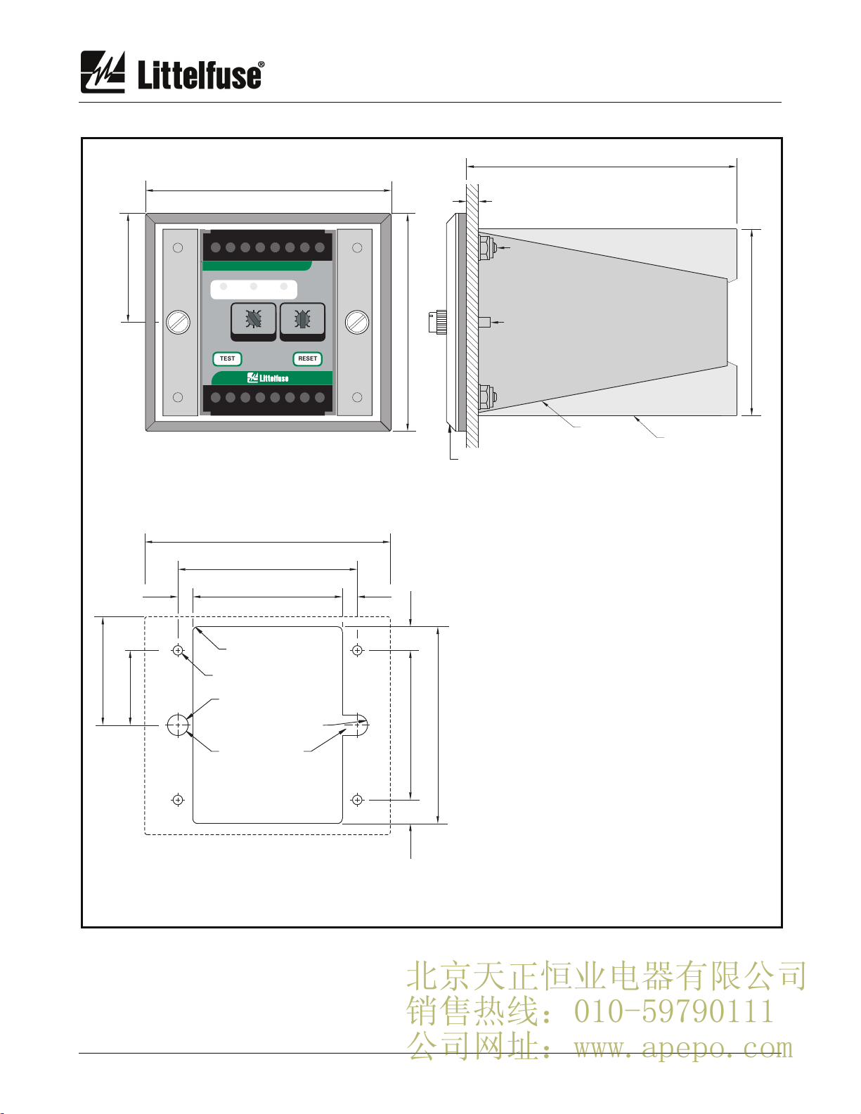
applications. The PGR-4704 has one output relay
with isolated normally open and normally closed
contacts for use in independent control circuits.
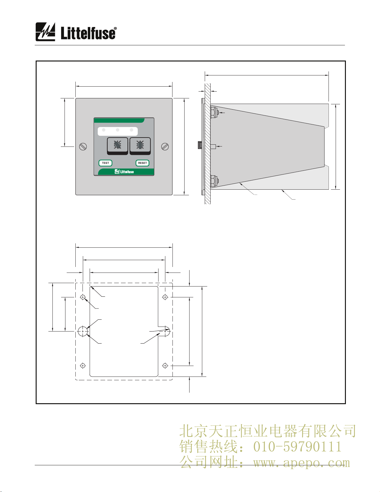
Additional features include LED trip and power
indication, autoreset or latching trips with front-panel
and remote reset, trip memory, test switch, self
diagnostics, 0- to 1-mA and 0- to 5-V analog outputs,
CT verification with LED indication, digital selector
switches, and switch-selectable algorithms for fixed-
frequency or variable-frequency applications.
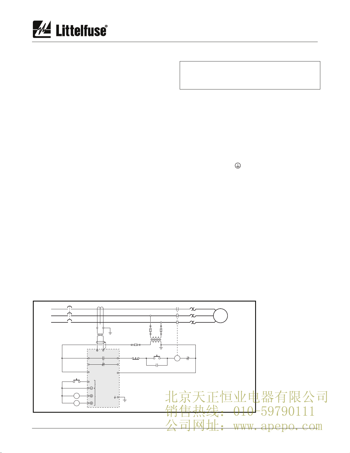
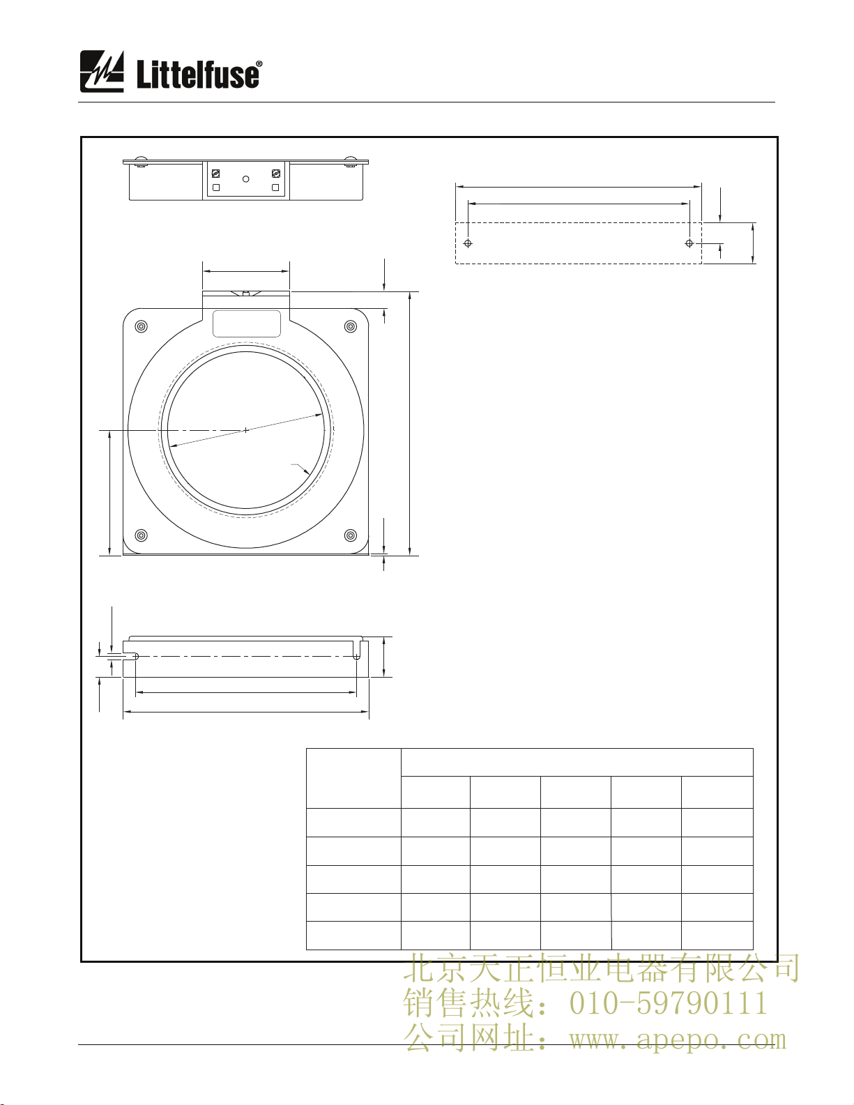
Ground-fault current is sensed by a PGC-5000-
series core-balance ground-fault current transformer.
The trip level of the ground-fault circuit is digital-
switch selectable from 10 to 5,000 mA. Trip time is
digital-switch selectable from 30 to 2,000 ms.
2. OPERATION
2.1 Configuration-Switch Settings
See Fig. 1.
2.1.1 Relay Operating Mode
Switch 1 is used to set the operating mode of the
output relay. In the fail-safe mode, the output relay
energizes when the ground-fault circuit is not
tripped. In the fail-safe mode, non-volatile memory
retains the trip status of the PGR-4704. If tripped,
and the supply voltage is cycled, the PGR-4704 will
remain tripped, with the trip relay de-energized and
the TRIP LED on, until reset.
In the non-fail-safe mode, the output relay
energizes when a ground-fault trip occurs. In the
non-fail-safe mode, trip status is not retained in non-
volatile memory.
2.1.2 Filter Selection
Switch 2 is used to select the filtering algorithm for
settings less than 1,000 mA. The selections are for
fixed-frequency (50/60 Hz) or variable-frequency
applications. The FIXED FREQUENCY setting uses
a DFT filter that allows lower trip levels to be used
by rejecting harmonics that can cause nuisance
tripping.
The VARIABLE FREQUENCY setting uses a
peak-detection algorithm with a wider band width for
fault detection in variable-frequency drive
applications.
The peak-detection algorithm is used for settings
greater than 500 mA.
2.1.3 CT Verification
Switch 3 is used to enable CT verification. In
the ON position, a trip will occur if the PGC-5000-
series current transformer is disconnected.
2.1.4 Reset Mode
Switch 4 is used to select autoreset or latching
trips. See Section 2.2.3.
2.1.5 Analog Output
Switch 5 is used to select analog-output scaling.
Selecting % OF 5 A results in full scale output (1 mA or
5 V) when ground-fault current is 5 A. Selecting
% OF SETTING results in full scale output when
ground-fault current equals the trip-level setting.
2.2 Front-Panel Controls
2.2.1 Ground-Fault Trip Level
The LEVEL (mA) selection switch is used to set the
ground-fault trip level. For ground-fault detection, the
ground-fault trip level must be substantially below the
prospective ground-fault current. To avoid
sympathetic tripping, the trip level must be above the
charging current of the protected feeder.
2.2.2 Ground-Fault Trip Time
The PGR-4704 has a definite-time trip
characteristic. The TIME (ms) selector switch is
used to set the ground-fault trip time for coordination
with upstream and downstream ground-fault
devices. Coordination requires the same trip level
for all ground-fault devices in a system and the trip
time to progressively increase upstream. The
amount of equipment removed from the system will
be a minimum if the first ground-fault device to
operate is the one immediately upstream from the
fault.
2.2.3 Reset
If the Reset Mode switch is in the LATCHING
position, a trip remains latched until the RESET switch
is pressed or the remote-reset terminals (6 and 7) are
momentarily connected. In the non-fail-safe relay
operating mode, cycling the supply voltage will also
reset the PGR-4704.
If the Reset Mode switch is in the AUTORESET
position, a trip will reset when the fault is removed.
The reset circuit responds only to a momentary
closure so that a jammed or shorted switch will not
prevent a trip. The front-panel RESET switch is
inoperative when the remote-reset terminals are
connected.
北京天正恒业电器有限公司
销售热线:010-59790111
公司网址:www.apepo.com