manuals.online logo
Brands
  1. Home
  2. •
  3. Brands
  4. •
  5. Little Giant
  6. •
  7. Water Pump
  8. •
  9. Little Giant 10E-CIA-SFS User manual

Little Giant 10E-CIA-SFS User manual

INTRODUCTION
This instruction sheet will provide you with information required to safely own and operate
the Little Giant 10E and 10S series pumps. The pump you have purchased is a submers-
ible effluent pump for use in basins or lift stations and suitable for pumping sewage,
effluent, wastewater and other non-explosive, non-corrosive liquids. The 10S Series sew-
age ejector pumps have a 2" spherical solids handling capability. The 10E Series sewage
effluent pumps have a 3/4" spherical solids handling capability.
This instruction sheet covers the standard models in this pump series. This form is applicable
to other models in this series not listed by catalog number in the replacement parts list
section of this pamphlet. If the catalog number of your pump is not listed in the replacement
parts section, then caution should be exercised when ordering replacement parts. Always
give the catalog number of your pump when ordering replacement parts.
The Little Giant unit you have purchased is of the highest quality workmanship and
material. It has been engineered to give you long and trouble-free service.
Little Giant pumps are carefully inspected, tested, and packaged to insure safe operation
and delivery. When you receive your pump, examine it carefully to determine that there
are no broken or damaged parts that may have occurred during shipment. If damage has
occurred, make notation and notify the firm from which you purchased the pump. They
will assist you in replacement or repair, if required.
Read instructions carefully before attempting to install, operate or service the Little Giant
pump. Know the pump applications, limitations, and potential hazards. Protect yourself
and others by observing all safety information. Failure to comply with instructions could
result in personal injury and/or property damage. Retain instructions for future refer-
ence.
SAFETY GUIDELINES
1. Do not use to pump flammable or explosive fluids such as gasoline, fuel oil, kerosene,
etc. Do not use in explosive atmospheres. Pump should only be used with liquids
compatible with pump component materials.
2. Do not handle pump with wet hands or when standing on a wet or damp surface, or
in water.
3. Do not use power cord for lifting the pump.
4. This pump is supplied with a grounding conductor and/or grounding-type attach-
ment plug. To reduce the risk of electric shock, be certain that it is connected to a
properly grounded grounding-type receptacle.
5. The National Electric Code requires a ground fault circuit interrupter (GFCI) be installed
in the branch circuit supplying fountain equipment, pools, etc.
6. In any installation where property damage and/or personal injury might result from an
inoperative or leaking pump due to power outages, discharge line blockage, or any
other reason, a backup system(s) and/or alarm should be used.
7. Support pump and piping when assembling and when installed, failure to do so may
cause piping to break, pump to fail, motor bearing failures, etc.
8. This pump’s motor housing is filled with a dielectric oil for motor heat transfer and
lifetime lubrication of the bearings. This oil is non-toxic to aquatic life; however,
suffocation can occur if oil is left on the water surface. If oil escapes the motor housing,
it can be removed from the surface quickly by placing newspapers on the water surface
to soak up the oil.
9. The pump motor is equipped with an automatic resetting thermal protector and may
restart unexpectedly. Protector tripping is an indication of motor overloading as a result
of excessively high or low voltage, inadequate wiring, incorrect motor connections or
a defective motor or pump.
ELECTRICAL CONNECTIONS
1. Check the pump label for proper voltage required. Do not connect to voltage other
than that shown.
2. If pump is supplied with a 3-prong electrical plug, the third prong is to ground the
pump to prevent possible electrical shock hazard. DO NOT REMOVE the third prong
from the plug. A separate branch circuit is recommended. Do not use an extension
cord. Do not cut plug from the cord. If the plug is cut or the cord is shortened, then
this action will void the warranty.
3. If the cord is equipped with stripped lead wires, such as on 230V models, be sure
that the lead wires are connected to a power source correctly. The green/yellow wire
is the ground, the other two are live.
4. Check local electrical and building codes before installation. The installation must
be in accordance with their regulations as well as the most recent National Electrical
Code (NEC).
5. To conform to the National Electrical Code all pumps must be wired with 14 AWG or
larger wire. For runs to 250’, 14 AWG wire is sufficient. For longer runs, consult a
qualified electrician or the factory.
6. Pump should be connected or wired to its own circuit with no other outlets or equipment
in the circuit line. Fuses and circuit breaker should be of ample capacity in the
electrical circuit.
7. The flexible PVC jacketed cord assembly mounted to the pump must not be modified
in any way, with the exception of shortening the cord to fit into a control panel. Any
splice between the pump and the control panel must be made within a junction box
and mounted outside of the basin and comply with the National Electrical Code.
OPERATION
1. Pump must be installed in a suitable gas tight basin which is at least 18" in diameter
and 24" deep, and vented in accordance with local plumbing codes.
2. 10E series features 1-1/2" female NPT discharge. 10S series features 2" female NPT
discharge.
3. Pump must be placed on a hard level surface. Never place pump directly on clay,
earth or gravel surfaces.
4. A check valve must be used in the discharge line to prevent backflow of liquid into
the basin. The check valve should be a free flow valve that will easily pass solids. Drill
a 3/16" hole in the discharge pipe approximately 1"–2" above the pump discharge
connection and below check valve to prevent air locking the pump.
CAUTION: For best performance of check valves, when handling solids install in a
horizontal position or at an angle of no more than 45°. Do not install check valve in a
vertical position, as solids may settle in valve and prevent opening on start-up.
5. Do not attempt to restrict the intake side of these pumps. Restricting the intake may
cause damage to the seal and may starve the pump. If you require reduced flow
rates, then place a valve on the discharge side of the pump or if flexible vinyl tubing
is used, a clamp can be used on the tubing to restrict the flow.
6. Do not let the unit operate dry. It is designed to be cooled by pumping fluid. You may
damage the seal and the motor may fail if the pump is allowed to run dry.
7. If the unit is going to be idle for a period of time, follow the cleaning instructions
outlined in the next section. Do not let the unit freeze in the wintertime. This may
cause cracking or distortion that may destroy the unit.
TESTING PUMP OPERATION
1. These pumps are equipped with a float operated mechanical switch.
2. When these pumps are installed in a basin with a sealed cover, switch operation cannot
be observed. The sump cover usually will have a spare hole that is plugged with a
rubber plug. This plug can be removed and switch operation can be observed.
3. Plug power cord into a grounded receptacle with voltage consistent with pump voltage
as indicated on pump nameplate.
4. Run water into pump until pump starts.
5. Be sure gate valve in discharge line is open.
6. Allow pump to operate through several on-off cycles.
SERVICE INSTRUCTIONS
MAKE CERTAIN THAT THE UNIT IS DISCONNECTED FROM THE POWER SOURCE
BEFORE ATTEMPTING TO SERVICE OR REMOVE ANY COMPONENT!
1. If pump does not operate properly, consult the troubleshooting chart. If trouble cannot
be located with the steps shown, consult your pump dealer or take pump to a Little
Giant authorized service center.
2. Do not remove the three socket head cap screws (item #11). The motor section on
your pump is permanently lubricated with dielectric oil and sealed at the factory.
Removal of these socket head cap screws by anyone other than an authorized Little
Giant service center will break the seal and void the warranty.
3. Periodic cleaning of the pump parts will prolong the LIFE and EFFICIENCY of the
pump. Refer to Figure 2 for the assembly and disassembly of the pumping head.
4. On 10E Series: Remove five screws (item #23) that hold screen base and base plate
to volute/plate.
On 10S Series: Remove four hex bolts (item #39) that hold volute to plate. Remove
volute.
Do not use strong solvents on impeller.
5. Be sure impeller turns freely after cleaning.
6. WARNING: DO NOT REMOVE IMPELLER. REMOVAL OF IMPELLER REQUIRES
SPECIAL TOOLS AND IS TO BE DONE ONLY BY AN AUTHORIZED SERVICE
CENTER. DO NOT REMOVE MOTOR HOUSING COVER. WARRANTY IS VOID IF
MOTOR HOUSING COVER, IMPELLER OR SEALS HAVE BEEN REMOVED. ANY
REPAIR ON MOTOR MUST BE DONE BY AN AUTHORIZED LITTLE GIANT SERVICE
CENTER.
7. Be certain power cord is in good condition and contains no nicks or cuts.
10E-CIA-SFS
10S-CIA-SFS
Submersible
Effluent Pumps Figure 1.
Little Giant
P. O. Box 12010
Oklahoma City, OK 73157-2010
405.947.2511 • Fax: 405.947.8720
www.LittleGiant.com
[email protected]
LIMITED WARRANTY
Little Giant #6E, #8E, #9#, #10E, #14EH, and #16EH Series Submersible Effluent
Pumps are recommended for use in sumps, basins or lift stations and suitable for pumping
basement drainage water, effluent, wastewater and other non-explosive, non-corrosive,
non-abrasive liquids not above 140°F with up to 3/4" spherical solids (1/2" on 6E models)
handling ability. (Not to be used for sewage water except to pump septic tank effluent.)
Little Giant #9S, #10S, #14S and #16S series Submersible Sewage Ejector Pumps are
recommended for use in sumps, basins or lift stations and suitable for pumping sewage,
effluent, wastewater and other non-explosive, non-corrosive, non-abrasive liquids not
above 140°F with up to 2" spherical solids handling ability. Each of the above noted Little
Giant products is guaranteed to be in perfect condition when it leaves our factory. During
the time periods and subject to the conditions hereinafter set forth, Little Giant Pump
Company, subsidiary of Franklin Electric Company, Inc., will repair or replace to the origi-
nal user or consumer any portion of your new Little Giant product which proves defective
due to materials or workmanship of Little Giant. Contact your nearest Authorized Little
Giant dealer for warranty service, At all times Little Giant shall have and possess the sole
right and option to determine whether to repair or replace defective equipment, parts, or
components, damage due to lightning or conditions beyond the control of Little Giant is
NOT covered by this warranty.
WARRANTY PERIOD
PUMPS: 12 months from date of installation or 18 months from date of manufacture,
whichever occurs first.
LABOR, ETC. COSTS: Little Giant shall in no event be responsible or liable for the cost
of field labor or other charges incurred by any customer in removing and/or affixing any
Little Giant product, part or component thereof.
This warranty will not apply:
1. to defects or malfunctions resulting from failure to properly install, operate, or main-
tain the unit in accordance with printed instructions provided
2. to failures resulting from abuse, accident or negligence
3. to normal maintenance services and the parts used in connection with such service
4. to units which are not installed in accordance with applicable local codes, ordinances
and good trade practices
5. unit is used for purposes other than for what it was designed and manufactured
6. if pump exposed to but not limited to the following: sand, gravel, cement, grease, plas-
ter, mud, tar, hydrocarbons, or hydrocarbon derivatives (oil, gasoline, solvents, etc.)
or other abrasive or corrosive substances.
7. if pump has been used for continuous pumping of suitable liquids above 140°F
8. if power cord has been cut or spliced
9. if pump has been dismantled by customer. (Dealer only can dismantle pump for field
service.)
RETURN OR REPLACED COMPONENTS: Any item to be replaced under the Warranty
must be returned to Little Giant at Oklahoma City, Oklahoma, or such other place as Little
Giant may designate, freight prepaid.
PRODUCT IMPROVEMENTS: Little Giant reserves the right to change or improve its
products or any portions thereof without being obligated to provide such a change or
improvement for units sold and/or shipped to such change or improvement.
DISCLAIMER: Any oral statements about the product made by the seller, the manufac-
turer, the representatives or any other parties, do not constitute warranties, shall not be
relied upon by the user, and are not part of the contract for sale. Seller’s and manufactur-
er’s only obligation, and buyer’s only remedy, shall be the replacement and/or repair by
the manufacturer of the product as described above. Neither seller nor the manufacturer
shall be liable for any injury, loss or damage, direct, incidental or consequential (includ-
ing, but not limited to, incidental or consequential damages for lost profits, lost sales,
injury to person or property, or any other incidental or consequential loss), arising out
of the use or the inability to use the product, and the user agrees that no other remedy
shall be available to it. Before using, the user shall determine the suitability of the product
for his intended use, and user assumes all risk and liability whatsoever in connection
therewith. The warranty and remedy described in this limited warranty is an EXCLUSIVE
warranty and remedy and is IN LIEU OF any other warranty or remedy, expressed or
implied, which other warranties and remedies are hereby expressly EXCLUDED, includ-
ing, but not limited to any implied warranty of MERCHANTABILITY OR FITNESS FOR A
PARTICULAR PURPOSE. Some States do not allow the exclusion or limitation of inciden-
tal or consequential damages, so the above limitation or exclusion may not apply to you.
This warranty gives you specific legal rights, and you may also have other rights which
vary from state to state.
In the absence of other suitable proof of the installation date, the effective date of this
warranty will be based upon the date of manufacture plus one year. Direct all notices, etc.
to: Service Department, Little Giant Pump Company, 3810 N. Tulsa, Oklahoma City, OK
73112.
DETERMINATION OF UNIT DATE OF MANUFACTURE: (9-87) month and year stamped on
pump and/or serial number on pump nameplate coded to indicate year of manufacture.
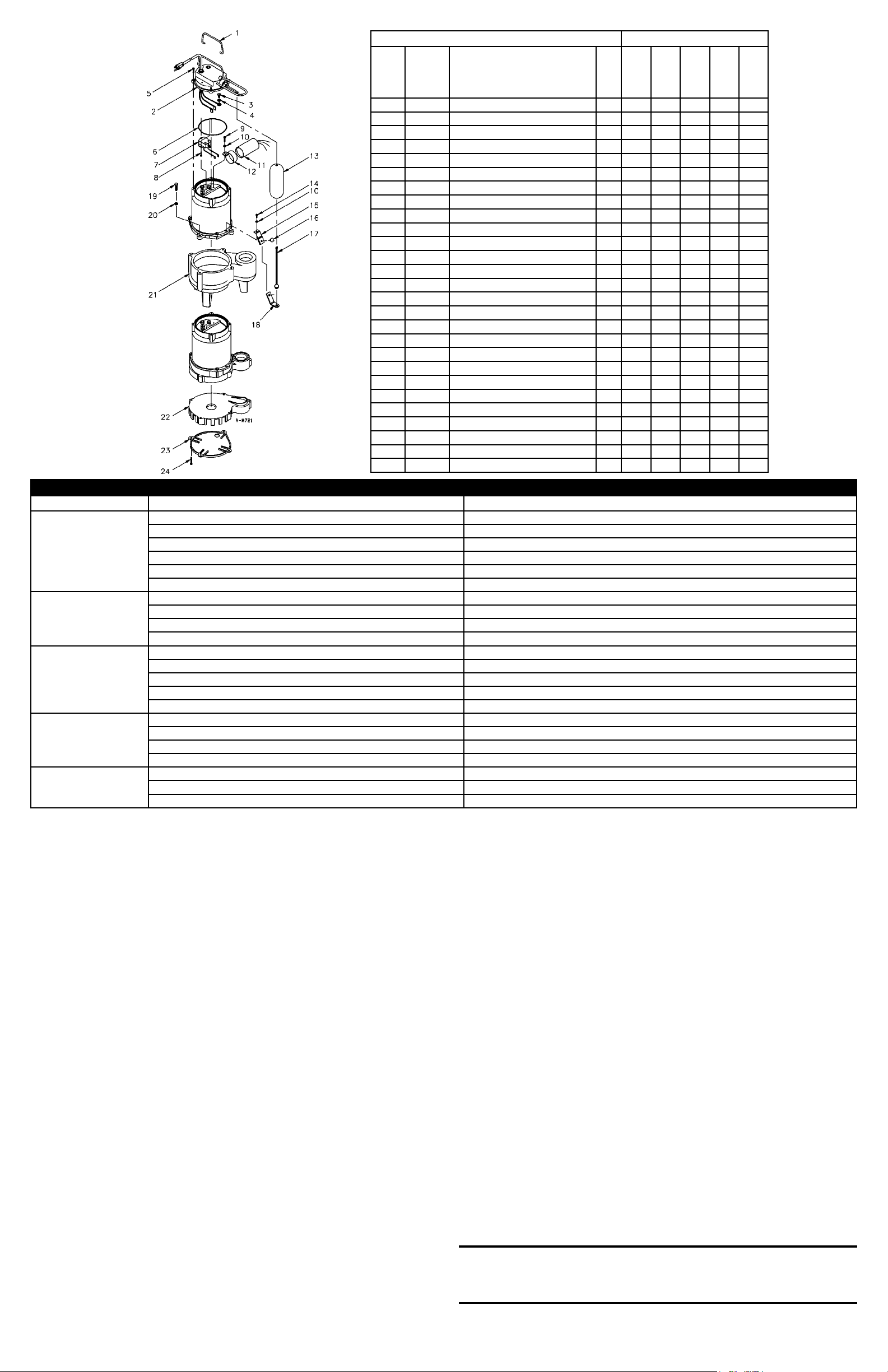
REPLACEMENT PARTS MODEL NO./CATALOG NO.
ITEM
PART
NO. DESCRIPTION QTY
10E-CIA-SFS
511350
10E-CIA-SFS
511355
10S-CIA-SFS
511550
10S-CIA-SFS
511555
10S-CIA-SFS
511565
1 108101 HANDLE 1 • • • • •
2 110349 COVER ASSEMBLY, 10FT, (115V) 1 • •
2 110350 COVER ASSEMBLY, 25FT, (115V) 1 • •
2 110351 COVER ASSEMBLY, 25FT, (230V) 1 •
3 902307 SCREW, #6-32 X 1/4 1 • • • • •
4 921028 WASHER, LOCK 1 • • • • •
5 909022 SCREW/WASHER, 10-24 X 5/8 4 • • • • •
5 106350 SWITCH HOUSING 1 • • • • •
6 928002 SEAL RING, NITRILE 1 • • • • •
7 950250 SWITCH 1 • • • • •
8 902431 SCREW, 8-18 X 1/2 2 • • • • •
9 902520 SCREW, 10-24 X 3/8 1 • • • • •
10 921023 WASHER, LOCK 2 • • • • •
11 950507 CAPACITOR ASSY., 10-SFS 1 • • • • •
12 110101 BRACKET, CAPACITOR 1 • • • • •
13 106362 FLOAT 1 • • • • •
14 902516 SCREW, TAPPING, 10-24 X 1/2 1 • • • • •
15 110100 RETAINER, FLOAT ROD STRAP 1 • • • • •
16 929451 PUSH-IN FASTENER 1 • • • • •
17 106381 ROD, FLOAT 1 • • • • •
18 106367 STRAP, FLOAT 1 • • • • •
19 915907 BOLT, HEX 4 • • •
20 921103 WASHER, LOCK 4 • • •
21 111415 VOLUTE 1 • • •
22 109150 BASE, SCREEN 1 • •
23 109151 PLATE, BASE 1 • •
24 909024 SCREW/WASHER 5 • •
©Copyright 2006 Little Giant
Form 994581 — 08/2006
Little Giant Print Services
For Parts or Repair, please contact . . . . . . . . . . . . . . . . . . . . . . . . . . . . . . . . . . . . . . .1.888.572.9933
For Technical Assistance, please contact. . . . . . . . . . . . . . . . . . . . . . . . . . . . . . . . . . .1.888.956.0000
www.LittleGiant.com
[email protected]
Figure 2.
TROUBLESHOOTING INFORMATION
PROBLEM PROBABLE CAUSES CORRECTIVE ACTIONS
Pump does not turn on.
Pump not plugged in. Plug in pump.
Circuit breaker shutoff or fuse removed. Turn on circuit breaker or replace fuse.
Accumulation of trash on float. Clean float.
Float obstruction. Check float path and provide clearance.
Defective switch. Have pump serviced by authorized service center
Defective motor. Have pump serviced by authorized service center.
Pump will not shut off.
Float or float rod obstruction. Check float and float rod path and provide clearance.
Pump is air locked. Shut power off for approximately 1 minute, then restart. Repeat several times to clear air from pump.
Liquid inflow matches pump capacity. Larger pump reqired.
Defective switch. Disconnect switch, check with ohmmeter. Open-infinitive resistance closed zero.
Pump runs but does not
discharge liquid.
Check valve installed backwards. Check flow indicating arrow on check valve body to ensure it is installed properly.
Check valve stuck or plugged. Remove check valve and inspect for proper operation.
Lift too high for pump. Check rating table.
Inlet to impeller plugged. Pull pump and clean.
Pump is air locked. (See corrective action above.)
Pump does not deliver
rated capacity.
Lift too high for pump. Check rated pump performance.
Low voltage, speed to slow. Check for proper supply voltage to make certain it corresponds to nameplate voltage.
Impeller or discharge pipe is clogged. Pull pump and clean. Check pipe for scale or corrosion.
Impeller wear due to abrasives. Replace worn impeller.
Pump cycles continually.
No check valve in long discharge pipe allowing liquid to drain back into basin. Install a check valve in discharge line.
Check valve leaking. Inspect check valve for correct operation.
Basin too small for inflow. Install larger basin.

This manual suits for next models

1

Other Little Giant Water Pump manuals

Little Giant WGP-55 User manual

Little Giant

Little Giant WGP-55 User manual

Little Giant BSP33V User manual

Little Giant

Little Giant BSP33V User manual

Little Giant PE-1 User manual

Little Giant

Little Giant PE-1 User manual

Little Giant VCMA-15 User manual

Little Giant

Little Giant VCMA-15 User manual

Little Giant 12E Series User manual

Little Giant

Little Giant 12E Series User manual

Little Giant 5-MSP Series User manual

Little Giant

Little Giant 5-MSP Series User manual

Little Giant JPC Series User manual

Little Giant

Little Giant JPC Series User manual

Little Giant WRS-6 User manual

Little Giant

Little Giant WRS-6 User manual

Little Giant PP-1 User manual

Little Giant

Little Giant PP-1 User manual

Little Giant HT-VCL-P Series User manual

Little Giant

Little Giant HT-VCL-P Series User manual

Little Giant LG-MPA33 User manual

Little Giant

Little Giant LG-MPA33 User manual

Little Giant 8E-CIA-RFS User manual

Little Giant

Little Giant 8E-CIA-RFS User manual

Little Giant PE-1H-PW Series User manual

Little Giant

Little Giant PE-1H-PW Series User manual

Little Giant 3E Series User manual

Little Giant

Little Giant 3E Series User manual

Little Giant Bottom Pick-up 5-MSPR User manual

Little Giant

Little Giant Bottom Pick-up 5-MSPR User manual

Little Giant 14S Series User manual

Little Giant

Little Giant 14S Series User manual

Little Giant 8-CBM User manual

Little Giant

Little Giant 8-CBM User manual

Little Giant 9EH-CIM User manual

Little Giant

Little Giant 9EH-CIM User manual

Little Giant 3-MDX Use and care manual

Little Giant

Little Giant 3-MDX Use and care manual

Little Giant HT-10EN-CIM User manual

Little Giant

Little Giant HT-10EN-CIM User manual

Little Giant 9EC Series User manual

Little Giant

Little Giant 9EC Series User manual

Little Giant 5MSP-WG User manual

Little Giant

Little Giant 5MSP-WG User manual

Little Giant VCMA-10 User manual

Little Giant

Little Giant VCMA-10 User manual

Little Giant 4-MD User manual

Little Giant

Little Giant 4-MD User manual

Popular Water Pump manuals by other brands

ITT Goulds Pumps Marlow 20EVP Series Installation, operation and maintenance instructions

ITT

ITT Goulds Pumps Marlow 20EVP Series Installation, operation and maintenance instructions

Graco 224826 instructions

Graco

Graco 224826 instructions

Espa DRAIN instruction manual

Espa

Espa DRAIN instruction manual

KNF N143 TRANSLATION OF ORIGINAL OPERATING AND INSTALLATION INSTRUCTIONS

KNF

KNF N143 TRANSLATION OF ORIGINAL OPERATING AND INSTALLATION INSTRUCTIONS

KNF SIMDOS 10 operating instructions

KNF

KNF SIMDOS 10 operating instructions

Pentair myers aplex Series Installation and service manual

Pentair

Pentair myers aplex Series Installation and service manual

Groz QSP-01 instruction manual

Groz

Groz QSP-01 instruction manual

T.I.P. Maxima 400 CX operating instructions

T.I.P.

T.I.P. Maxima 400 CX operating instructions

Mistral MSP 12 A1 Translation of the original instructions

Mistral

Mistral MSP 12 A1 Translation of the original instructions

Marco UP10/E-BR Instructions for use

Marco

Marco UP10/E-BR Instructions for use

BUSCH RA 0165 D instruction manual

BUSCH

BUSCH RA 0165 D instruction manual

Efco MP 300 Operators instruction book

Efco

Efco MP 300 Operators instruction book

Sears CRAFTSMAN 390.269152 owner's manual

Sears

Sears CRAFTSMAN 390.269152 owner's manual

Wilo Rexa MINI3-S Installation and operating instructions

Wilo

Wilo Rexa MINI3-S Installation and operating instructions

SFA SANISUB STEEL Operating & installation manual

SFA

SFA SANISUB STEEL Operating & installation manual

Neptun NGP-E 105 Original operating instructions

Neptun

Neptun NGP-E 105 Original operating instructions

Gomco 270 Operation, maintenance and service manual

Gomco

Gomco 270 Operation, maintenance and service manual

Hans Premium Water 2 owner's manual

Hans

Hans Premium Water 2 owner's manual

manuals.online logo
manuals.online logoBrands
  • About & Mission
  • Contact us
  • Privacy Policy
  • Terms and Conditions

Copyright 2025 Manuals.Online. All Rights Reserved.