manuals.online logo
Brands
  1. Home
  2. •
  3. Brands
  4. •
  5. Little Giant
  6. •
  7. Water Pump
  8. •
  9. Little Giant 10SH-CIM User manual

Little Giant 10SH-CIM User manual

INTRODUCTION
Little Giant Submersible 10SH Series Sewage Ejector Pumps are recommended for use in basins or lift
stations and suitable for pumping sewage, effluent, wastewater and other non-explosive, non-corrosive
liquids. The 10SH Series Sewage Ejector Pumps have 1-1/4" spherical solids handling capability.
Automatic operation can be achieved with the use of the RFS Remote Float Switch. Other accessories
such as basins, check valves and covers are also available.
UNPACKING
Little Giant pumps are carefully packaged, inspected and tested to insure safe operation and delivery.
When you receive your pump, examine it carefully to determine that there are no broken or damaged parts
that may have occurred during shipment. If damage has occurred, make notation and notify the firm from
which you purchased the pump and they will assist you in replacement or repair, if required.
SPECIFICATIONS
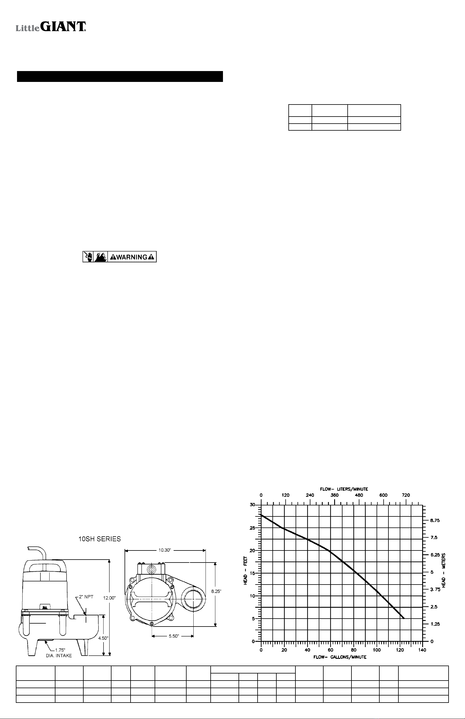
Discharge: 10SH Series 2" NPT vertical
Intake: 10SH Series 1.75" diameter opening
Housing: Cast iron
Volute: Cast iron
Impeller: Vortex design nylon, with pressure relief vanes
Motor: Split phase induction, 1750 RPM, with automatic reset thermal overload protection
Hardware: 300 Series stainless steel
Bearing: Double shielded ball
Shaft Seal: Mechanical, spring loaded, stationary carbon with Nitrile boot and rotating ceramic seat
Power Cord: 16 AWG 3-conductor copper stranded
Cooling: The motor housing contains a cooling oil to provide cooling for the motor and to lubricate
bearings and seals. These pumps are capable of operating with the motor housing partially
exposed for extended periods of time, providing sufficient motor cooling and bearing
lubrication. However, for the best cooling and longest motor life, the liquid level being
pumped should normally be above the top of the cast iron motor housing.
SAFETY GUIDELINES
WARNING: RISK OF ELECTRIC SHOCK. This pump is supplied with a grounding conductor and/or
grounding type attachment plug. To reduce the risk of electric shock, be certain that it is connected
to a properly grounded grounding type receptacle.
Your pump is equipped with a 3-prong electrical plug. The third prong is to ground the pump to prevent
possible electrical shock hazard. Do not remove the third prong from the plug. A separate branch circuit
is recommended. Do not use an extension cord.
When a pump is in a basin, etc., do not touch motor, pipes or water until unit is unplugged or shut off. If
shut-off box is not accessible, call the electric company to shut off service to the house, or call your local
fire department for instructions. Failure to follow this warning can result in fatal electrical shock.
The flexible PVC jacketed cord assembly mounted to the pump must not be modified in any way, with the
exception of shortening the cord to fit into a control panel. Any splice between the pump and the control
panel must be made within a junction box and mounted outside of the basin, and comply with the National
Electrical Code. Do not use the power cord for lifting the pump.
The pump motor is equipped with an automatic resetting thermal protector and may restart unexpectedly.
Protector tripping is an indication of motor overloading as a result of operating the pump at low heads (low
discharge restriction), excessively high or low voltage, inadequate wiring, incorrect motor connections, or
a defective motor or pump.
1. Read all instructions and Safety Guidelines thoroughly. Failure to follow the guidelines and instructions
could result in serious bodily injury and/or property damage.
2. DO NOT USE TO PUMP FLAMMABLE OR EXPLOSIVE FLUIDS SUCH AS GASOLINE, FUEL OIL,
KEROSENE, ETC. DO NOT USE IN EXPLOSIVE ATMOSPHERES OR HAZARDOUS LOCATIONS
AS CLASSIFIED BY NEC, ANSI/NFPA70. FAILURE TO FOLLOW THIS WARNING CAN RESULT IN
PERSONAL INJURY AND/OR PROPERTY DAMAGE.
3. During normal operation the pump is immersed in water. Also, during rain storms, water may be present
in the surrounding area of the pump. Caution must be used to prevent bodily injury when working near
the pump:
a. The plug must be removed from the receptacle prior to touching, servicing or repairing the pump.
b. To minimize possible fatal electrical shock hazard, extreme care should be used when changing
fuses. Do not stand in water while changing fuses or insert your finger into the fuse socket.
4. Do not run the pump in a dry basin. If the pump is run in a dry basin, the surface temperature of the
pump will rise to a high level. This high level could cause skin burns if the pump is touched and will
cause serious damage to your pump.
5. Do not oil the motor. The pump housing is sealed. A high grade dielectric oil devoid of water has been
put into the motor housing at the factory. Use of other oil could cause serious electric shock and/or
permanent damage to the pump.
6. This pump’s motor housing is filled with a dielectric lubricant at the factory for optimum motor heat
transfer and lifetime lubrication of the bearings. Use of any other lubricant could cause damage and
void the warranty. This lubricant is non-toxic; however, if it escapes the motor housing, it should be
removed from the surface quickly by placing newspapers or other absorbent material on the water
surface to soak it up, so aquatic life is undisturbed.
INSTALLATION
Pump must be installed in a suitable gas tight basin which is at least 18" in diameter and 30" deep, and
vented in accordance with local plumbing codes.
10SH Series Sewage Pumps feature a 2" female NPT discharge.
Pump can be installed with ABS, PVC, polyethylene or galvanized steel pipe. Proper adapters are required
to connect plastic pipe to pump.
Pump must be placed on a hard level surface. Never place pump directly on clay, earth or gravel surfaces.
A check valve must be used in the discharge line to prevent backflow of liquid into the basin. The check
valve should be a free flow valve that will easily pass solids.
CAUTION: For best performance of check valves, when handling solids install in a horizontal position or at
an angle of no more than 45°. Do not install check valve in a vertical position as solids may settle in valve
and prevent opening on start-up.
When a check valve is used drill a 3/16" hole in the discharge pipe approximately 1" to 2" above the pump
discharge connection and below check valve to prevent air locking of the pump.
WIRING
Check local electrical and building codes before installation. The installation must be in accordance with
their regulations as well as the most recent National Electrical Code (NEC).
To conform to the National Electrical Code all pumps must be wired with 14 AWG or larger wire. For runs
to 250', 14 AWG wire is sufficient. For longer runs, consult a qualified electrician or the factory.
Pump should be connected or wired to its own circuit with no other outlets or equipment in the circuit line.
Fuses and circuit breaker should be of ample capacity in the electrical circuit. See chart below.
H.P. VOLTAGE FUSE OR CIRCUIT
BREAKER AMPS
1/2 115 20
1/2 230 15
REMOTE FLOAT SWITCH LEVEL
CONTROL
The RFS series pumps are equipped with a remote float switch level control. This level control is sealed in
a polypropylene float cylinder. For automatic operation, the pump must be plugged or wired into a remote
float switch. Pump will run continuously if plugged directly into an electrical outlet.
When the level rises in the basin, the cylinder floats up with the level. When the cylinder position is at an
angle of about 45° the switch activates and starts the pump motor.
As the level draws down, the cylinder floats down and when it is again at an angle of about 45°, the switch
deactivates, and the pump motor stops.
NOTE: BE CERTAIN PUMP IS SECURE IN BASIN AND CYLINDER FLOATS UNOBSTRUCTED WITHOUT
TOUCHING THE BASIN WALLS OR PLUMBING.
REMOTE FLOAT SWITCH INSTALLATION
1. The float switch consists of three parts:
a. switch
b. cord clamp
c. clamp screw
NOTE: If screw is lost, use a #10-16 x 1/2" long tapping screw.
2. Attach cord clamp to pump cover as shown in Figure 3. The clamp must be positioned as shown to
allow free operation of float. Be sure to locate pump and switch power cords away from switch float.
3. A 3-1/2" tether length is recommended. When a tether length of 3-1/2" is used, a minimum basin
diameter of 18" is recommended. The tether length is measured as shown in Figure 3.
4. After desired tether length is established hand tighten clamp screw.
5. TESTING: Without water in basin plug pump power cord into switch in-line-plug. Plug switch into
outlet. Lift float and watch for pump to operate. Do not run pump for more than 5 seconds.
OPERATION
TESTING PUMP OPERATION
RFS SERIES SEWAGE EJECTOR PUMPS
1. These pumps are equipped with a remote float switch.
2. These pumps are installed in a basin with a sealed cover, so switch operation cannot be observed.
The sump cover usually will have a spare hole that is plugged with a rubber plug. This plug can be
removed and switch operation can be observed.
3. Plug power cord and remote float switch power cord into a grounded receptacle with voltage consistent
with pump voltage as indicated on pump nameplate.
4. Run water into basin until pump starts.
5. Be sure gate valve in discharge line is open.
6. Allow pump to operate through several on-off cycles.
MANUAL SEWAGE EJECTOR PUMPS
The pump cord for these pumps can be plugged directly into a properly grounded receptacle with voltage
consistent with pump nameplate for continuous pump operation.
CAUTION: This type of operation should be used only for emergency use or when a large volume of water
is to be pumped. Pump must not be allowed to run dry. If pump is run dry, it may damage pump and void
the warranty.
MAINTENANCE AND SERVICE
If pump does not operate properly, consult the Troubleshooting Chart. If trouble can not be located with
these steps shown, consult your pump dealer or take pump to a Little Giant authorized service center.
CAUTION: When working on pump or switch, always unplug pump power cord in addition to removing
fuse or shutting off circuit breaker before working on pump.
CLEANING IMPELLER AND VOLUTE
1. Remove screws that hold volute to motor housing.
2. Remove volute and clean impeller and volute passage. Do not use strong solvents on impeller.
3. Be sure impeller turns freely after cleaning.
4. WARNING: DO NOT REMOVE IMPELLER. REMOVAL OF IMPELLER REQUIRES SPECIAL TOOLS
AND IS TO BE DONE ONLY BY AN AUTHORIZED SERVICE CENTER.DO NOT REMOVE MOTOR
HOUSING COVER. WARRANTY IS VOID IF MOTOR HOUSING COVER, IMPELLER OR SEALS HAVE
BEEN REMOVED.
ANY REPAIR ON MOTOR MUST BE DONE BY AN AUTHORIZED LITTLE GIANT SERVICE CENTER.
10SH-CIM
10SH-CIA-RFS
Figure 1.
Model No. Catalog No. Listing(s) HP Volts Solids Size
(dia. in.)
Amps/
Watts
GPM @ Head Shut Off P.S.I. Power Cord
(ft.)
Wt.
(lbs.)
Dimensions
(H x L x W in In.)
10' 15' 20' 25'
10SH-CIM 511420 UL/CSA 1/2 115 1-1/4" 11/900 100 80 55 20 28' 12.1 15 41.5 12.00 x 10.3 x 8.25
10SH-CIM 511480 UL/CSA 1/2 208-240 1-1/4" 5.5/900 100 80 55 20 28' 12.1 15 41.5 12.00 x 10.3 x 8.25
10SH-CIA-RFS 511520 UL/CSA 1/2 115 1-1/4" 11/900 100 80 55 20 28' 12.1 15 41.5 12.00 x 10.3 x 8.25
Figure 2.
Little Giant
P. O. Box 12010
Oklahoma City, OK 73157-2010
405.947.2511 • Fax: 405.947.8720
www.LittleGiant.com
[email protected]
LIMITED WARRANTY
SUMP, EFFLUENT & RESIDENTIAL SEWAGE
Little Giant 10SH Series Submersible Sewage Ejector Pumps are recommended for use in sumps, basins
or lift stations and suitable for pumping sewage, effluent, wastewater and other non-explosive, non-corrosive,
non-abrasive liquids not above 140°F with up to 1-1/4" spherical solids handling capability.
Each of the above-noted Little Giant products is guaranteed to be in perfect condition when it leaves our
factory. During the time periods and subject to the conditions hereinafter set forth, LITTLE GIANT PUMP
COMPANY, Subsidiary of FRANKLIN ELECTRIC COMPANY, INC., will repair or replace to the original user
or consumer any portion of your new LITTLE GIANT product which proves defective due to materials or
workmanship of LITTLE GIANT. Contact your nearest Authorized Little Giant Dealer for warranty service.
At all times Little Giant shall have and possess the sole right and option to determine whether to repair or
replace defective equipment, parts, or components. Damage due to lightning or conditions beyond the
control of LITTLE GIANT is NOT COVERED BY THIS WARRANTY.
WARRANTY PERIOD
PUMPS: 12 months from date of installation or 18 months from date of manufacture, whichever comes first.
LABOR, ETC. COSTS: LITTLE GIANT shall IN NO EVENT be responsible or liable for the cost of field labor
or other charges incurred by any customer in removing and/or affixing any LITTLE GIANT product, part
or component thereof.
THIS WARRANTY WILL NOT APPLY:
1. to defects of malfunctions resulting from failure to properly install, operate, or maintain the unit in
accordance with printed instructions provided
2. to failures resulting from abuse, accident or negligence
3. to normal maintenance services and the parts used in connection with such service
4. to units which are not installed in accordance with applicable local codes, ordinances and good trade
practices
5. unit is used for purposes other than for what it was designed and manufactured
6. if pump exposed to but not limited to the following: sand, gravel, cement, grease, plaster, mud, tar,
hydrocarbons, or hydrocarbon derivatives (oil, gasoline, solvents, etc.) or other abrasive or corrosive
substances
7. if pump has been used for continuous pumping of suitable liquids above 140°F
8. if power cord has been cut to less than 3'
9. if pump has been dismantled by customer. (Dealer only can dismantle pump for field service.)
RETURNED OR REPLACED PRODUCT: Any product to be replaced under the warranty must be returned
to LITTLE GIANT at 301 North MacArthur Blvd., Oklahoma City, OK 73127-6616 or such other place as
LITTLE GIANT may designate, freight prepaid.
PRODUCT IMPROVEMENTS: Little Giant reserves the right to change or improve its products or any
portions thereof without being obligated to provide such a change or improvement for units sold and/or
shipped to such change or improvement.
DISCLAIMER: Any oral statements about the product made by the seller, the manufacturer, the representa-
tives or any other parties, do not constitute warranties, shall not be relied upon by the user, and are not
part of the contract for sale. Seller’s and manufacturer’s only obligation, and buyer’s only remedy, shall be
the replacement and/or repair by the manufacturer of the product as described above. Neither seller nor
the manufacturer shall be liable for any injury, loss or damage, direct, incidental or consequential (including,
but not limited to, incidental or consequential damages for lost profits, lost sales, injury to person or
property, or any other incidental or consequential loss), arising out of the use or the inability to use the
product, and the user agrees that no other remedy shall be available to it. Before using, the user shall
determine the suitability of the product for his intended use, and user assumes all risk of liability whatsoever
in connection therewith. The warranty and remedy described in this limited warranty is an EXCLUSIVE
warranty and remedy and is IN LIEU OF any other warranty or remedy, expressed or implied, which other
warranties and remedies are hereby expressly EXCLUDED, including but not limited to any implied
warranty of MERCHANTABILITY OR FITNESS FOR A PARTICULAR PURPOSE. Some states do not allow
the exclusive or limitation of incidental or consequential damages, so the above limitation or exclusion may
not apply to you. This warranty gives you specific legal rights, and you may also have other rights which
vary from state to state.
In the absence of other suitable proof of the installation date, the effective date of this warranty will be
based upon the date of manufacture plus one year. Direct all notices, etc., to: Service Department,
LITTLE GIANT PUMP COMPANY, 301 N. MacArthur Blvd., Oklahoma City, OK 73127-6616.
DETERMINATION OF UNIT DATE OF MANUFACTURE: (9-87) month and year stamped on pump and/or
serial number on pump nameplate coded to indicate year of manufacture.
©Copyright 2006 Little Giant
Form 994403 — 10/2006
Little Giant Print Services
For Parts or Repair, please contact . . . . . . . . . . . . . . . . . . . . . . . . . . . . . . . . . . . . . . .1.888.572.9933
For Technical Assistance, please contact. . . . . . . . . . . . . . . . . . . . . . . . . . . . . . . . . . .1.888.956.0000
www.LittleGiant.com
[email protected]
Figure 3.
TROUBLESHOOTING INFORMATION
PROBLEM PROBABLE CAUSES CORRECTIVE ACTION
Pump does not turn on.
NOTE: Before troubleshooting automatic control,
check to see that pump operates on manual control.
To do this, unplug from in-line float switch plug.
Plug pump power cord into wall outlet. If pump
works, proceed to check switch, if not, fault is in
pump or power supply.
Pump not plugged in. Plug in pump.
Circuit breaker shutoff or fuse removed. Turn on circuit breaker or replace fuse.
Accumulation of trash on mercury float switch. Clean float.
Remote float switch obstruction. Check float path and provide clearance.
Defective switch. Disconnect switch, check w/ohmmeter. Open-infinitive resistance, closed-zero.
Defective motor. Have pump serviced.
Pump will not shut off.
Remote float switch obstruction. Check float path and provide clearance.
Pump is air locked.
Shut power off for approximately 1 minute, then restart. Repeat several times to clear air
from pump. If system includes a check valve, a 3/16" hole should be drilled in discharge
pipe approximately 2" above discharge connections.
Liquid inflow matches pump capacity. Larger pump required.
Defective switch. Disconnect switch, check w/ohmmeter, Open-infinitive resistance, closed-zero.
Loose connection in level control wiring. Check control wiring.
Pump runs but does not discharge liquid.
Check valve installed backwards. Check flow indicating arrow on check w/ohmmeter, Open-infinitive resistance, closed-zero.
Check valve stuck or plugged. Remove check valve and inspect for proper operation.
Lift too high for pump. Check rating table.
Inlet to impeller plugged. Pull pump and clean.
Pump is air locked. (See corrective action above.)
Pump does not deliver rated capacity.
Lift too high for pump. Check rated pump performance.
Low voltage, speed too slow. Check for proper supply voltage to make certain it corresponds to nameplate voltage.
Impeller or discharge pipe is clogged. Pull pump and clean. Check pipe for scale or corrosion.
Impeller wear due to abrasives. Replace worn impeller.
Pump cycles continually.
No check valve in long discharge pipe allowing liquid to drain
back into basin. Install a check valve in discharge line.
Check valve leaking. Inspect check valve for correct operation.
Basin too small for inflow. Install larger basin.
ITEM
NO.
PART
NO. PART DESCRIPTION QTY.
MODEL NO./CAT. NO.
10SH-CIM 511420
10SH-CIM 511480
10SH-CIM-RFS
511520
10SH-CIM-RFS
511525
1 909025 Screw/Washer #10-24 x 1 3/4" 4 ● ● ● ●
2 110054 Housing, Relay 1 ● ● ● ●
3 951541 Power Cord, 115V, 15ft 1 ● ●
3 951536 Power Cord, 230V, 15ft 1 ●
3 951551 Power Cord, 230V, 10M 1 ●
4 112120 Clamp, Strain Relief 1 ● ● ● ●
5 902409 Screw, Tap, #8-18 X 3/4" 3 ● ● ● ●
6 901306 Screw, #6-32 X 1/4" 3 ● ● ● ●
7 950930 Relay, 115V 1 ● ● ●
7 950934 Relay, 230V 1 ●
8 928019 Seal Ring, Nitrile 1 ● ● ● ●
9 951907 Bolt, Hex, 1/4-20 X 1" 4 ● ● ● ●
10 921103 Washer, Lock, 1/4' Split Ring 4 ● ● ● ●
11 111311 Volute 1 ● ● ● ●
12 950904 Ty-Rap 1 ● ●
13 950315 Remote Float Switch, 15ft 1 ●
13 905317 Remote Float Switch, 25ft 1 ●
14 927027 Loop Clamp 1 ● ●
15 902516 Screw, Tap, #10-24 x 1/2" 1 ● ●

This manual suits for next models

1

Other Little Giant Water Pump manuals

Little Giant 6EC Series User manual

Little Giant

Little Giant 6EC Series User manual

Little Giant HT-10EN-CIM User manual

Little Giant

Little Giant HT-10EN-CIM User manual

Little Giant F Series User manual

Little Giant

Little Giant F Series User manual

Little Giant PES-A-PW User manual

Little Giant

Little Giant PES-A-PW User manual

Little Giant WGP-65-PW User manual

Little Giant

Little Giant WGP-65-PW User manual

Little Giant 5.5-ASP User manual

Little Giant

Little Giant 5.5-ASP User manual

Little Giant 506166 User manual

Little Giant

Little Giant 506166 User manual

Little Giant 5-ASP-FS User manual

Little Giant

Little Giant 5-ASP-FS User manual

Little Giant 6E-CIA-SFS User manual

Little Giant

Little Giant 6E-CIA-SFS User manual

Little Giant WRS-6 User manual

Little Giant

Little Giant WRS-6 User manual

Little Giant BIOVORT FILTER Series User manual

Little Giant

Little Giant BIOVORT FILTER Series User manual

Little Giant B-180 Series User manual

Little Giant

Little Giant B-180 Series User manual

Little Giant PWM Series User manual

Little Giant

Little Giant PWM Series User manual

Little Giant WGFP-50 User manual

Little Giant

Little Giant WGFP-50 User manual

Little Giant 8E-CIM User manual

Little Giant

Little Giant 8E-CIM User manual

Little Giant Eliminator Series User manual

Little Giant

Little Giant Eliminator Series User manual

Little Giant 5-ASP-FS User manual

Little Giant

Little Giant 5-ASP-FS User manual

Little Giant PE-1H-PW Series User manual

Little Giant

Little Giant PE-1H-PW Series User manual

Little Giant 2-MDQ-SC User manual

Little Giant

Little Giant 2-MDQ-SC User manual

Little Giant FLS-400 User manual

Little Giant

Little Giant FLS-400 User manual

Little Giant AP1 User manual

Little Giant

Little Giant AP1 User manual

Little Giant EC-400 Series User manual

Little Giant

Little Giant EC-400 Series User manual

Little Giant 15EC-CIA-SFS User manual

Little Giant

Little Giant 15EC-CIA-SFS User manual

Little Giant VCC-20-P User manual

Little Giant

Little Giant VCC-20-P User manual

Popular Water Pump manuals by other brands

Sears HYDRO-GLASS 390.250290 owner's manual

Sears

Sears HYDRO-GLASS 390.250290 owner's manual

Remco LP-BK01 General Information and Wiring Instructions

Remco

Remco LP-BK01 General Information and Wiring Instructions

Grundfos DME 60 Installation and operating instructions

Grundfos

Grundfos DME 60 Installation and operating instructions

Mindray BeneFusion uVP Instructions for use

Mindray

Mindray BeneFusion uVP Instructions for use

AL-KO HW 3000 Instructions for use

AL-KO

AL-KO HW 3000 Instructions for use

SNOWJOE SUNJOE 24V-XFP5-CT-RM Operator's manual

SNOWJOE

SNOWJOE SUNJOE 24V-XFP5-CT-RM Operator's manual

Efco MP 3000 Operator's instruction manual

Efco

Efco MP 3000 Operator's instruction manual

LONCIN 25ZB21-1.2Q owner's manual

LONCIN

LONCIN 25ZB21-1.2Q owner's manual

Fimco High-Flo HFP-45060-113 owner's manual

Fimco

Fimco High-Flo HFP-45060-113 owner's manual

Sandpiper S30 Service & operating manual

Sandpiper

Sandpiper S30 Service & operating manual

Sea Joule Marine 750-7AH-TD instruction manual

Sea Joule Marine

Sea Joule Marine 750-7AH-TD instruction manual

DAYLIFF AQUASTRONG SMART 45 Installation & operating manual

DAYLIFF

DAYLIFF AQUASTRONG SMART 45 Installation & operating manual

Bijur Delimon D2 operating instructions

Bijur Delimon

Bijur Delimon D2 operating instructions

Pfeiffer Vacuum HILOBE 2704 operating instructions

Pfeiffer Vacuum

Pfeiffer Vacuum HILOBE 2704 operating instructions

Elitech SVP-7 user manual

Elitech

Elitech SVP-7 user manual

SFA SANICONDENS Plus installation instructions

SFA

SFA SANICONDENS Plus installation instructions

Tecnogas 11940 Operation manual

Tecnogas

Tecnogas 11940 Operation manual

Master Pumps MPXI11MULTIPC18 Original instructions

Master Pumps

Master Pumps MPXI11MULTIPC18 Original instructions

manuals.online logo
manuals.online logoBrands
  • About & Mission
  • Contact us
  • Privacy Policy
  • Terms and Conditions

Copyright 2025 Manuals.Online. All Rights Reserved.