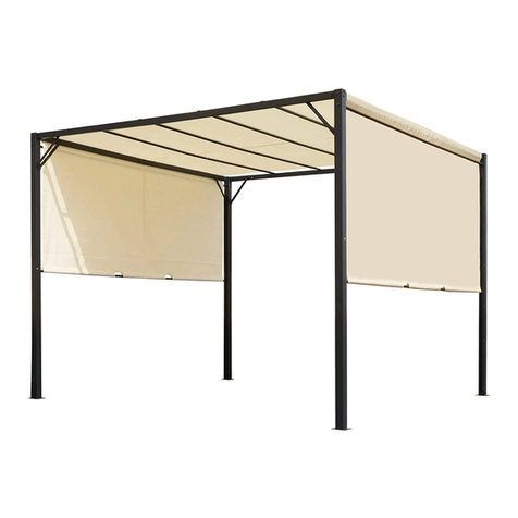
Living Culture Onetangi User manual

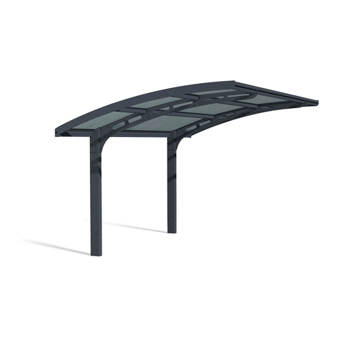
Onetangi ALUMINUM PERGOLA
MANUAL
SIZE: 5X4 6X4 7X4 8X3.6

<2/23>
INSTALLATION NOTES
Before you start to install products ,please read below notes:
1.This is a general versioan manual .make sure tht you review the design when
placing an order and read this manual several times before you start to assemble
pergola ,this installation steps can be referred to in this manual ,However ,other
specific details such as motor position ,drainage direction ect. should be accord to
the drawing of the order placed
2.Check the package list and confirm all items on the list ! Do not throw away any
package until the pergola is installed successfully
3.Minimum 3 people are required during the installation
4.It needs 2 people to lift the product parts from the package ,please put the
products very gentle , it is better to cover a carpet or hard paper box on the
flooring to protect it from scratching
5.You should better to screw the pergola on a flat concrete floor or do
pre-embedded into the floor when its height up to 2800mm.
6.You should remove the film coated on the products entirely during the
installation ,because it is difficult to remove them after explosion under hot
temperature
7.Please do not DIY our product and take use of the other alternative accessories
when you change the original design ,which will void your warranty
8.We hold no responsibility for any damage caused due to human factor ,
especially incorrect assembly
9.During the installation process, if you encounter any uncertainties, please refer
to the installation instructions on the product page of the website.

A-2
A-3
A-4
A-5
A-6
A-1
driven
blade
led light
blade
blade
driven
rod
B-2
B-4
B-5
B-6
B-1
C-2
C-3
C-1
C-1
D-2
D-1
driven
rod
D-1
D-2
code name photosection
post
post
post
post
post
post
A-1
A-2
A-3
A-4
motor
motor
A-5
A-6
gutter
gutter
gutter
gutter
gutter
gutter
B-1
B-2
B-3
B-4
B-5
B-6
B-3
C-1
C-2
C-3
D-1
D-2
E-2
E-3
E-4
E-5
E-6
E-1
E-1
E-2
E-3
E-4
E-5
E-6
gutter
cover
gutter
cover
gutter
cover
gutter
cover
gutter
cover
gutter
cover
code name photosection
<3/23>

M8 washer
M8*80 SUS hex expansion
bolt
post end cover
4.2*16 cross tapping screw
driven blade cover (R)
4.2*19 cross drilling screw
cross tapping screw(4*20)
middle post end cover
M5 hex blot nut
M5*16 cross screw
decoration
cover
2-bay stengthing
accessory
hex screw (M8*20)
6*20 cross drilling screw
1
2
3
4
5
6
7
8
9
code name photo
10
11
12
13
base plate
15
16
17
18
corner connector
14
SUS hex screw (M8*12)
A1 post
decoration cover
HARDWARE
Note:
The silicone sealant is not allowed
to ship,we don't offer this item.
please purchase it in local
code name photo
allen wrench(5mm)
remote
control system
(2motor and 2 led light)
19
20
21
22
23
blade pivot cover
4*14 cross drilling screw
∅8*M6*5 shoulder screw
blade pivot holder
cross tapping screw (5*20)
24
25
26
<4/23>

Tools
INSTALLATION
STEP 1:Assemble the post with base plate
A-2
A-5
A-3
A-6
A-4
A-1
14 5
2
1.1 put the base plate docorative cover into the post before you screw them.
please note the decoration cover of wire post is different .
1.2、
Fasten the base
plate with the
posts after you
put the
decoration cover
in each post
1.3、
Fasten it
2
2
3
Tip:
A1 is essentail post ,the cable
go through inside and don't break
the cable to cause power leakage
<5/23>
hand drill cross bar hammer
marker 16mm wrench security hat
rubber hammer
electrical
drill
∅14mm
drill bar
electric spirit
level
tape
ladderX3

STEP 2:Assemble the pergola frame :do assemble roller gutter
with posts first
2.2 Stand the middle post and
assemble one side frame
Screw the gutter with post
but keep it loosen
A-3
22
fasten it tight
2.1 Inset the gutter into
the groove of post
Tip:
Assemble the pergola frame on
the floor and make it stand
Tips:
1.Please ensure the pergola frame is
correct before you assemble
2.It needs at least 2 people to make
the post stand
<6/23>

2.3 Assemble the remain pergola frame
2.4 Assemble the remain frame
B-6
<7/23>

STEP 3:Adjust the pergola position and fix the posts on the floor
3.1 Adjust the position .measure
the diagonal lines and ensure
the diagnal are equal.
3.2 It needs two workers to install
the midlle gutter connect accessory .
ne man push gutters to ensure min gap
the other man screw it .don't forget
to do silicone sealant when installationfinished
3.3 Install the L shape
strengthing accessory
3.5 Adjust the position
measure the diagonal lines
and ensure the diagnal
are equal.
3.6 Mark the drill
holes on the ground 3.7 Drill holes 3.8 Stuff the expanion
bolt into concrete
3.9 Fasten the base
plate on the floor
3.10 Fasten the base
plate on the floor
3.11 Finished
3.4 Put the connector
at four corners
of gutter
3.12 Fix the 2 bay gutter connection
blade pivot holder
Note:
If you find the holder at connection was installed
in advance ,then ignore this step .because
sometime the roller has risk to broken .So we need
to pack it seperately .
Tips:
1.Ensure the post in correct position ,
and stand 90 degree with floor.
2.Before you fasten the screws ,you should
double check the pergola position .
<8/23>

11
12
4.1 Take out the blade without driven cover
from the package , there are 2 pieces
4.2 Screw the driven blade cover with driven blade
4.3 Check the drawing ,and mark the positions of led light blades and
driven blade on the gutter
C-1
STEP 4 :Settle the blades
C-1
<9/23>

4.4 Ensure the blades direction and position ,start to settle blades on the roof
fasten them when all blades settled and confrimed
there is no fault
4.4-2 When all blades
seetles ,then fasten
the covers
19
20
4.4-3 Connect the LED light
blade cable with electric
cable in gutter
C-3
motor
4.4-4 Fasten the driven
blade with motor
14
13
Tips :
Settle the blades in correct position
Tip:
screw the motor
with driven blade
is essential part
<10/23>

STEP 5:Connect to the power
5.1 Before inset the
control system ,you
should connect the
voltage cable
5.2 Inset the control system
into the post A1
tree plugs are LED light blade cable
5.3、Connect the cables
5.4、
Connect the cable with domestic
voltage cable , you should prepare
a local standard plug
note:
there are two cable for
led light ,please link
them base on labels .
Note :
there are two motor cables
please connect them accord
to lables.
motor A
cable
motor
B cable
motor A
motor B
led light
cable 1
brown:live line(L)
blue:neatural line(N)
yellow:earth line(E)
23
A-1
Tips:
1、connect the cable as design
2、earth line is essential
3、RCCB is essential when you install
this product
Tips:
Seal the needless plug
by electric worker .
<11/23>

STEP 6: Install the driven rod and check the electric cables
Fasten the driven rod with
blades from inside to screw
6.2 Learn to remote controller system
6.2-1 Press and hold this button
until the light next to it
starts to flash
6.2-2 Press and hold the stop
button on remote until
led light stop to flash
channel display
led light switch
channel+
stop
adjust light
channel-
close bladesopen blades
led light switchadjust light
D-1
D-2
Tips:
1、Two bays driven rods must
be symmetrical
2、Driven rods should be outside ,
or the bades can not open
6.1 Install the driven rod
D-1
21
6.2-3 Check the remote function
<12/23>
Type 1
Type 2
Channel 01:motor 1
Channel 02:motor 2
There are two types of remote , one is simple type
without any zip screen ,the other is type 2 , you can
remote the pergola and zip screen at one remote .The
remote was pre-seted type 1 .and press channel
to exchange to type 2 by yourself
channel 01:motor 1
channel 02:motor 2
channel 03:zip screen 1
channel 04:zip screen 2
channel 05:zip screen 3
channel 06:zip screen 4
channel 07:zip screen 5
channel 08:zip screen 6
channel C1:control all motors
channel C2:controll all zip screens
channel C3:control all devices
6.2-4 Remote system logics
channel 01:(motor A)
press open button,motor A open
press stop button,motor A stop
press close button ,motor B close
two seconds fastthan motor A
press stop button, motor A stopped
channel 02:(motor B)
press open button ,motor A open one second fast
then motor B
press the stop button ,both motors are stopped
press close button,motor B can close indepently
Tip:motor A can oepn indepently,but when
it close ,the motor B should close first
Tip:the motor B open after motor A but you can close
motor B indepently

STEP 8:Install the gutter cover and post end cover
8.1 Use rubber hammer to knock the gutter
cover into groove, note width edge is inner side
7
9
10
8.2 Install the L shape post covers
COMPLETE
8.3 Install the middle post post covers
E-2
E-3
E-4
E-5
E-6
E-1
8
10
9
<13/23>
STEP 7:If there is zip screen device on the pergola,please
install zip screen before STEP 8

9.1、the PCCB is essential during installation
9.2、check the motor function
9.3、check the remote function
9.3、check the louver movement and noise
9.4、check the led light function
9.5、check the other device function
STEP 9 : Check the pergola function
<14/23>

<15/23>
HOW TO USE TUYA APP
1. Prepare a public wifi for the pergola
2. Open the phone bluetooth and TUYA app
Tip:
it needs 2.4GHz wifi
STEP1 :Open tuya app
2. Search door window
(WIFI) in the catagory
3. input the wifi
password
1、Open tuya app
and click add device
4. start to link
5、press and hole the
button until the blue
indicate light flash
6. click confirm
7, select quick flash 8、wait for link 9. sucess 10. select pergola
to control it
11. operation panel

A
B
C
<16/23>
How to authorize account to family members
一、 TUYA APP
When you connect to tuya app successfully ,you can share the account to your family members
TIPS:
1the owner's phone (A) connect to pergola ,he can operate the pergola by his phone A,
2.the other family members also download TUYA app and singn in
1. Create a family group in the phone A
share
1、creat a family
group
2、click my family 3、name the faily group 4、click into the
goup and link to
pergola as before
5、share to the other
family members
6、click into
family
group
7. join this family
goup
8. input the invite
code
9. confirm and
successly join
10. you can try to
operate the pergola on
the phone

WALL-MOUNTED MANUAL
A-1
A-2
A-3
B-2 B-4
B-5
B-6
B-1
B-3
Hardware list
expansion plug(M14*75)
wood screw (M10*100)
30mm cap
27
28
29
17mm wrench
<17/23>

STEP 1:Install the wall-mounted gutter first
2.1 Take use of electric spirit level
to mark the gutter position
2.2 Mark the holes position through the
pre-drill holes on the gutter
2.4 Stuff the expansion
plug into the holes
27
2.3 Drill φ14 mm holes
on the wall
28
2.6 Stuff the cap
30
2.5 Use wrench to screw
the gutter on the wall
Tip:
check the gutter position
before you fasten the screw
B-3
B-2
B-3
B-2
<18/23>

A-1
2.1-1 Fasten the gutter
with post
2.1 Assemble one bay pergola frame
2.2-2 Loosen these two screws
2.2-3 Inset the gutter into
the junction
A-2
B-6
2.2.Assemble the other bay frame as same as step 2
B-4
B-5
A-3
STEP 2 : Assemble the pergola frame
注意:
框架安装好后,在打孔安装立柱
底座与地面固定的拉爆螺丝前,
必务按图复核尺寸
4
5
2.2-4 Fasten the
screw first
2.2-5 Fasten the screws at
up and botton of gutter
<19/23>

9
10
screw the blade
pivot covers
Tips:
1.When you settle the blades ,you should fasten the blade pivot
covers when each 3 pcs of blades settled
2.When the blade vertical to wall ,you should install the again wall
side driven rod first. and input power to open the blades to fix the
wall mounted side driven rod throgh blade gaps
Install the remain work as same as previous steps
<20/23>
Tip:
Attention:the power must be cut
down during the installation
Other manuals for Onetangi
1
Other Living Culture Tent manuals