LK009P Manual V4.1
1.CPU process control, count scores accurately.
2.Prevent pulling out tickets.
3.Prevent motor idling.
4.Easier to clean up the blocked tickets.
5.Mantissa memory (When the tickets run out,after putting new
tickets the device will restart to work automatically).
6.The wire part is made by SMT technology,quality and stability.
7.Adopt high quality and high-speed motor,continuously dispense
tickets without pause.
Product Features
1.According to the need of machine’s motherboard,switch the output
to NC or NO, switch the input to High level or Low level.
2.Put the tickets into the guide slot, the ticket dispenser will start to
install tickets automatically.(or hold down the “manual”key to install
the tickets manually).
3.The ticket dispenser can be used after connecting the power and
signal wires.
4.The panel displays the following information.
A. Exhaustion of tickets - slow flash (about 1 flash per second).
B. Normal ticketing - medium speed flash (approximately 2 flashes per second).
C. Abnormal alarm - fast flashing (about 3 flashes in 1 second).
Instructions for use
Power&Communication
OUT-Signal OUT
+12V-Power“+”
GND-Power“-”
IN-Trigger IN
G
F
H
The panel displays the following information
Exhaustion of tickets:slow flash (about1 flash
per second).
Normal ticketing:medium speed flash
(approximately 2 flashes per second).
Abnormal alarm:fast flashing (about 3 flashes
in 1 second).
Ticket status: Indicator light off.
Input level:
Low level input trigger
High level input trigger
A
manual:
For installing tickets
manually and testing
C
Output mode
NC. Normally closed
NO. Normally open
B
D
Reverse:
For cleaning up
the blocked
tickets and testing
Mounting holes:
With a square neck
screw diameter of 4mm
E
A
G
B
C
D
E
H
F
4 pin connector wire
can be option
20PCS/SET
Low level input trigger
High level input trigger
DC 12V±10%
load current
<50mA
≤1.2A
Output mode OC
Output Signal
Speed of tickets 300mm/s
Meas
Low level requirement:<3V
Low level requirement:<0.5V
High level requirement:>1.5V
High level requirement:>4.5V
30ms,<650mA
Individual
packaging
Carton
packaging
Without wire
With wire
Without wire
With wire
128*104*130mm
369g
388g
8.32KG
7.93KG
530*265*280mm
Meas
Gross
weight
Gross
weight
Package
Performance parameter
Operating voltage
Operating current
Ticket guide:
when jammed, gently
press down on the Ticket
guide andpull it outwards.
Communication circuit
Motor
Ticket outlet
Figure 2
Game machine
Number of tickets
being outleted
Control
signals
Master
Device
Slave
Device
Control the
motor run or
stop outlet
tickets
ON
OFF
ON
GND
Motor run
ON
OFF
OFF
ON
Motor stop Motor run
Motor status
Motor status
T
OFF
T=300ms
<0.5V
>4.5V
>1.5V
<3V
Anti-jamming
function on Ticket Outlet
Output Signal
Figure 3
Motor stop
Motor stopMotor stop
(NC)
Ticket Outlet
Output Signal
(NO)
Ticket Outlet
Output Signal
(NC)
Ticket Outlet
Output Signal
(NO)
Ticket Outlet
Output Signal
Anti-jamming
function off
Master input
control signals
Normal
high level
Normal
low level
Likang Electronic Technology Co.,Ltd.
www.lk.cm
VDD
signal
GND GND Figure 1
Ticket
outlet
Game machine
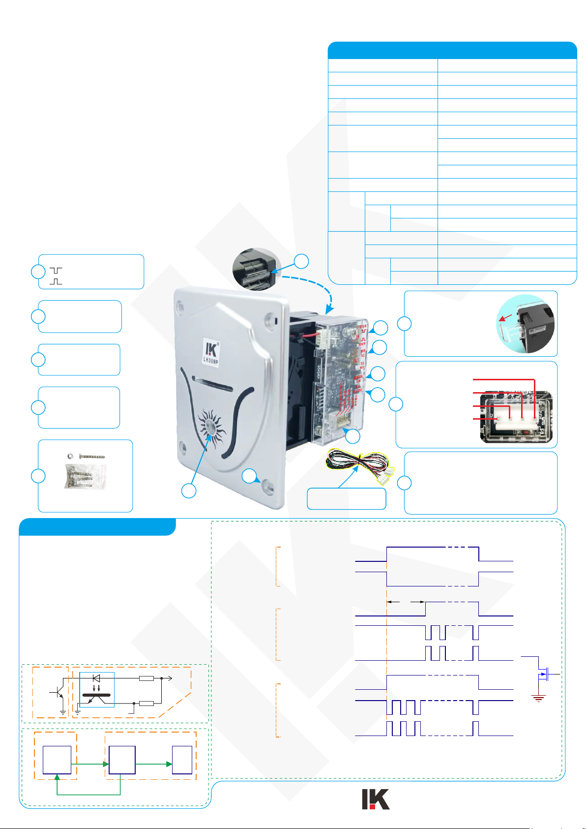
Description of interface circuit and communication
relationship of ticket outlet:
1.The output signal circuit of the ticket outlet is
triode collector or MOS drain open circuit output
mode. When it is used,users are advised to use
optocouplers to receive signals when designing the
interface circuit (see Figure 1).
2.Game machine is Master device, ticket outlet is
Slave device.
3.The relationship of the Master inputing
control signal, the Slave outputing signal,
and motor is shown in Figure 3. The status
workflow is shown in Figure 2.


