LM Dental Tracking System Reader User manual

User Manual
LM Dental Tracking System™ Reader

2
This manual is valid starting from:
LM Dental Tracking System™’s Reader 2.14.3
This manual is connected to LM Dental Tracking System™’s Server and it is recommended to
read also Manual for LM Dental Tracking System™’s Server.
Manufacturer, Marketing and Sales
LMDental
LM-Instruments Oy
Norrbyn Rantatie 8
FI-21600 Parainen, Finland
Tel. +358 2 4546 400
www.lm-dental.com, www.dentaltracking.com
Copyright
Copyright 2018 LM-Instruments Oy. All rights reserved. The contents of this manual may be
changed without notice. No part of this manual may be reproduced in any form or by any
means without permission in writing from LM-Instruments Oy.

3
CONTENT
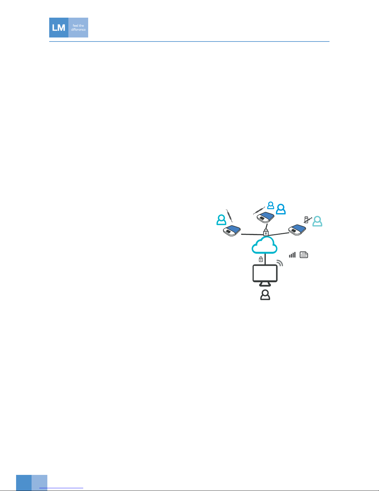
1. Introduction .................................................................................................................................................4
2. Safetyinstructions.......................................................................................................................................5
2.1 Safety notices ......................................................................................................................................5
2.2 General safety instructions for the reader..............................................................................................5
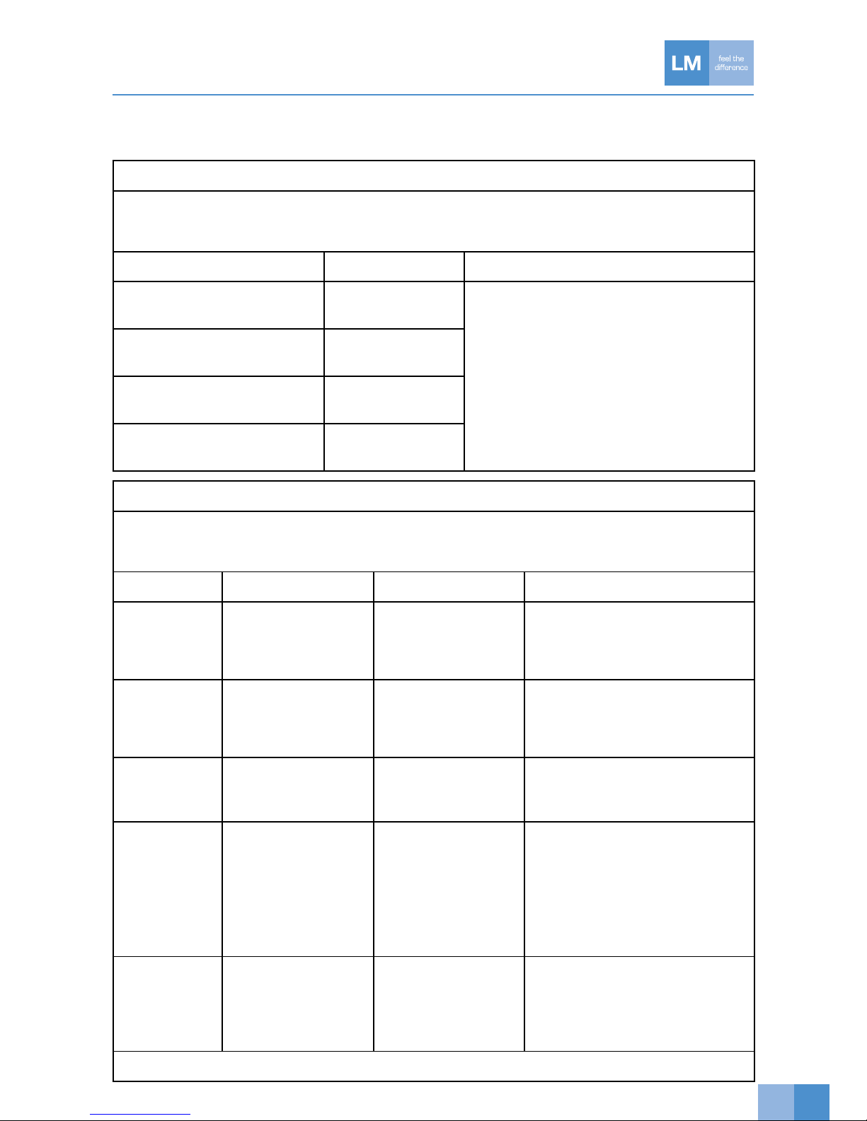
2.3 EMC Guidance and manufacturer’s declaration ....................................................................................7
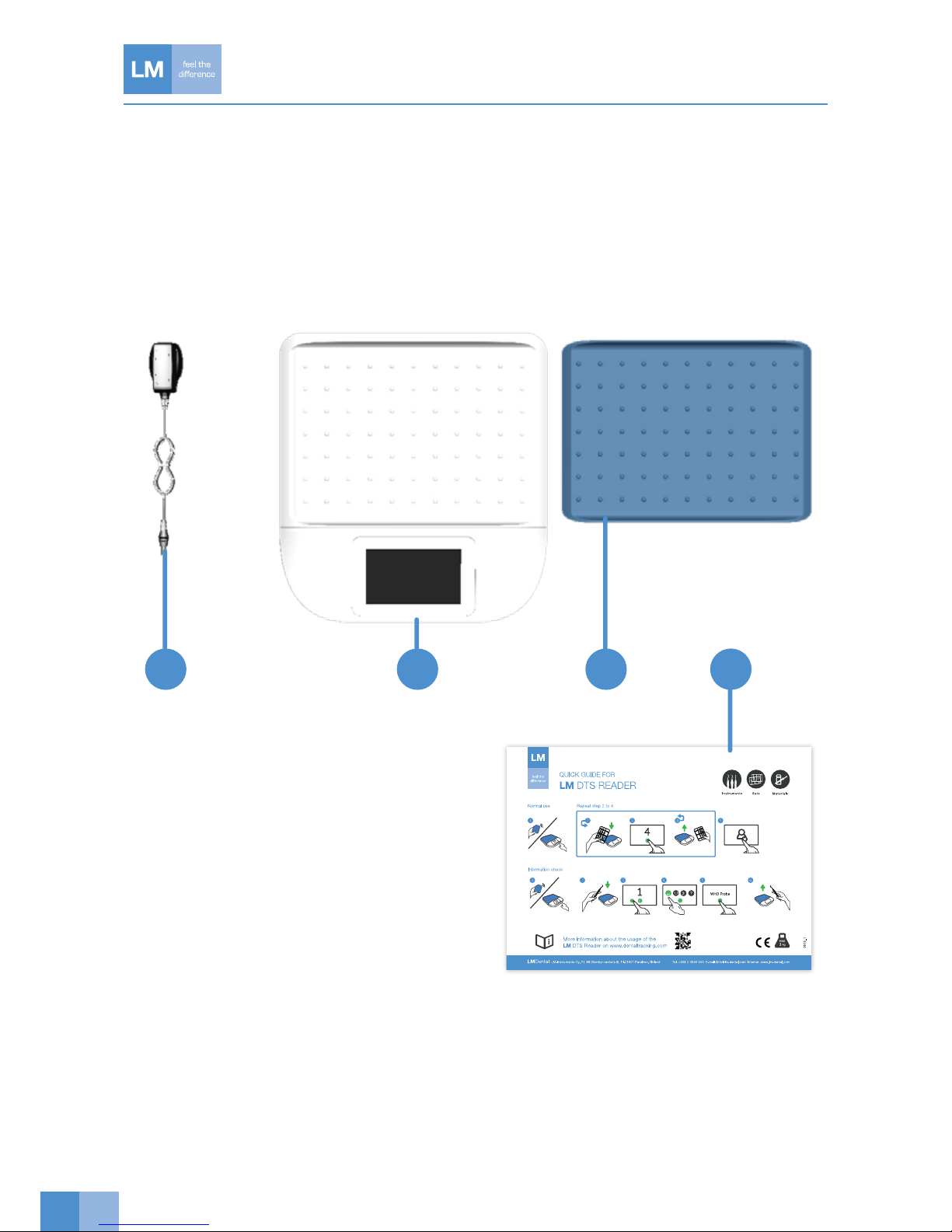
3. Contents of the delivery ............................................................................................................................10
3.1 Contents ............................................................................................................................................10
3.2 Reader ...............................................................................................................................................11
3.3 User interface of the reader ................................................................................................................12
3.4 Reader UI icons..................................................................................................................................13
3.5 Activity icons ......................................................................................................................................14
3.6 System glossary.................................................................................................................................15
4. Taking the Reader into use........................................................................................................................18
4.1 Installation ..........................................................................................................................................18
4.2 Reader activation ...............................................................................................................................18
4.3 Normal use – only one configured activity...........................................................................................18
4.4 Normal use ........................................................................................................................................18
4.5 Logging in with an RFID card..............................................................................................................18
5. Using the Reader.......................................................................................................................................19
5.1 Startup and shutdown........................................................................................................................19
5.2 Information search..............................................................................................................................19
5.3 Reading articles with an auxiliary device connected to the reader .......................................................19
5.4 Reader settings ..................................................................................................................................19
5.5 Registering new instrument ................................................................................................................19
5.6 Reader HID mode use and registering new instruments through the server ........................................20
6. Error/alert situations ..................................................................................................................................21
6.1 Error/alert description and resolution ..................................................................................................21
6.2 Warnings............................................................................................................................................22
7. Cleaning and maintenance..........................................................................................................................22
7.1 Recommended cleaning procedures ..................................................................................................22
7.2 Maintenance ......................................................................................................................................22
8. Troubleshooting.........................................................................................................................................23
8.1 Network failure ...................................................................................................................................23
9. Technical data ...........................................................................................................................................23
10. Warranty ....................................................................................................................................................24

4
1. INTRODUCTION
Foreword
This is the user manual for LM Dental Tracking System™ Reader. Later referred as to “DTS Reader”. Read and
understand this manual before you use the product. If there are any questions regarding the contents of this
manual, please contact LM-Instruments Oy. Ensure this User Manual is easily available for all users.
Intended and prohibited uses of the product
LM Dental Tracking System™ is used to record and track (chosen) activities made to articles registered in the
system. Articles can be e.g. different kinds of tools like dental hand instruments or materials like dental filling
materials.
Do not use DTS Reader where it is not intended to be used. If you are unsure about your operation, please
contact your local dealer or place of purchase.
Description of the LM Dental Tracking System™
LM Dental Tracking System™ (later referred to as “DTS”)
consists of a server and several readers connected to it. The
communication is encrypted (HTTPS) between the readers
and the server. Readers record activities to the server and get
configuration from the server.
Users can be given access to the server to access
web-based UI to e.g. view logs and configure
the system. The communication between the server
user and the server is encrypted (HTTPS).
General Requirements
Special precautions are necessary to this product regarding EMC (Electro Magnetic Compatibility).
It is necessary to install the product and put it into service as described in the EMC data in Section 2.4,
“EMC Guidance and manufacturer’s declaration”, on page 7.
Portable and mobile RF (Radio Frequency) communications equipment can have an unwanted effect
on the product.
Connect the product to electricity and network supply which meets the requirements in the Technical data.
Service
Only approved service persons are permitted to do servicing to this product. The maintenance procedures
which are introduced in this manual are for the user. Users must obey the maintenance measures to keep safe
and efficient operation of the product.
https://
END USERS
SERVER USER
SERVER
REPORTS, LOGS, TRACKING
LM Dental
Tracking
System™

5
2. SAFETYINSTRUCTIONS
2.1 Safety notices
The safety notices shown on this page are used to identify safety messages in these instructions:
WARNING indicates a dangerous situation that, if not prevented, could cause
death or injury.
CAUTION indicates a dangerous situation that, if not prevented, could cause
minor or moderate injury.
NOTICE indicates a situation that, if not prevented, could result in material
damage.
2.2 General safety instructions for the reader
Metal surfaces may affect reader performance.
No modification of this equipment is allowed.
Do not open the cover plate of the reader.
Use only approved power source, the technical data in section 9.
Do not step on the reader.

6
Do not sit on the reader. Max load 5 pounds or 2 kilograms.
If the reader has been in the cold, allow it to warm up at room temperature for at least
6 hours before switching on, in order to allow condensation formed
to evaporate.
Always check that the DTS Reader, cables and connectors are in operational use.
If the DTS Reader or cables has been damaged, DO NOT USE the DTS Reader.
The reader is intended for indoor use only.
System is not used for medical treatment decisions.
Basic recommendation is that the reader is on all the time. However the user has to
turn it off before transportation.
Device is not intended for use in conjunction with flammable agents or anaesthetics.
A warning that the DTS Reader should not be used adjacent to or stacked with other
equipment and that if adjacent or stacked use is necessary, the DTS Reader should
be observed to verify normal operation in the configuration in which it will be used.
Note
The manufacturer of the DTS Reader may provide a description or list of equipment with which
the DTS Reader has been tested in a stacked or adjacent configuration and with which stacked
or adjacent use is permitted.

7
2.3 EMC Guidance and manufacturer’s declaration
Guidance and manufacturer’s declaration - electromagnetic emissions
The DTS Reader is intended for use in the electromagnetic environment specified below. The customer or the user of the DTS Reader should
ensure that it is used in such an environment.
Use of accessories and cables other than those specified may result in increased emissions of the DTS Reader.
Emission test Compliance Electromagnetic environment - guidance
RF emissions
CISPR 11
Group 1 The DTS Reader is suitable for use in all establishments,
including domestic establishments and those directly
connected to the public low-voltage power supply network
that supplies buildings used for domestic purposes.
The DTS Reader uses RF energy only for its internal function.
Therefore, its RF emissions are very low and are not likely to
cause any interference in nearby electronic equipment.
RF emissions
CISPR 11
Class B
Harmonic emissions
IEC 61000-3-2
Class A
Voltage fluctuations/flicker emissions
IEC 61000-3-3
Complies
Guidance and manufacturer’s declaration - electromagnetic immunity
The DTS Reader is intended for use in the electromagnetic environment specified below. The customer or the user of the DTS Reader should
ensure that it is used in such an environment.
Use of accessories and cables other than those specified may result in decreased immunity of the DTS Reader.
Immunity test IEC 60601 test level Compliance level Electromagnetic environment - guidance
Electrostatic
discharge (ESD)
IEC 61000-4-2
±6 kV contact
±8 kV air
±6 kV contact
±8 kV air
Floors should be wood, concrete or ceramic
tile. If floors are covered with synthetic material,
the relative humidity should be at least 30
percent.
Electrical fast
transient/ burst
IEC 61000-4-4
±2 kV for power supply lines
±1 kV for input/output lines
±2 kV for power supply lines
±1 kV for input/output lines
Mains power quality should be that of a typical
commercial or hospital environment.
Surge
IEC 61000-4-5
±1 kV line(s) to line(s)
±2 kV line(s) to earth
±1 kV line to line Mains power quality should be that of a typical
commercial or hospital environment.
Voltage dips,
short interrup-
tions and voltage
variations on power
supply input lines
IEC 61000-4-11
<5 % UT(>95 % dip in UT)
for 0.5 cycle
40 % UT(60 % dip in UT)
for 5 cycles
70 % UT(30 % dip in UT)
for 25 cycles
<5 % UT(>95 % dip in UT)
for 5 sec
<5 % UT (>95 % dip in UT)
for 0.5 cycle
40 % UT (60 % dip in UT)
for 5 cycles
70 % UT(30 % dip in UT)
for 25 cycles
<5 % UT(>95 % dip in UT)
for 5 sec
Mains power quality should be that of a typical
commercial or hospital environment. If the
user of the DTS Reader requires continued
operation during power mains interruption,
it is recommended that the DTS Reader be
powered from an uninterruptible power supply
or battery.
Power frequency
(50/60 Hz)
magnetic field
IEC 61000-4-8
3 A/m 3 A/m Power frequency magnetic fields should be at
levels characteristic of a typical location in a
typical commercial or hospital environment.
NOTE UT is the AC mains voltage prior to application of the test level.

8
Guidance and manufacturer’s declaration - electromagnetic immunity
The DTS Reader is intended for use in the electromagnetic environment specified below. The customer or the user of the DTS Reader should
ensure that it is used in such an environment.
Use of accessories and cables other than those specified may result in decreased immunity of the DTS Reader.
Immunity test IEC 60601 test level Compliance level Electromagnetic environment - guidance
Conducted RF
IEC 61000-4-6
Radiated RF
IEC 61000-4-3
3 Vrms
150 kHz to 80 MHz
3 V/m
80 MHz to 2,5 GHz
3 Vrms
3 V/m
Portable and mobile RF communications
equipment should be used no closer to any
part of the DTS Reader including cables,
than the recommended separation distance
calculated from the equation applicable to the
frequency of the transmitter.
Recommended separation distance:
d = 1,2√P
d = 1,2√P 80 MHz to 800 MHz
d = 2,3√P 800 MHz to 2,5 GHZ
where Pis the maximum output power rating
of the transmitter in watts (W) according to
the transmitter manufacturer and dis the
recommended separation distance in metres
(m).
Field strengths from fixed RF transmitters as
determined by an electromagnetic site survey,
ashould be less than the compliance level in
each frequency range. b
Interference may occur in the vicinity of
equipment marked with the following symbol:
NOTE1 At 80 MHz and 800 MHz, the higher frequency range applies.
NOTE2 These guidelines may not apply in all situations.
Electromagnetic propagation is affected by absorption and reflection from structures, objects and people.
a Field strengths from fixed transmitters, such as base stations for radio (cellular/cordless) telephones and land mobile radios, amateur radio,
AM and FM radio broadcast and TV broadcast cannot be predicted theoretically with accuracy. To assess the electromagnetic
environment due to fixed RF transmitters, an electromagnetic site survey should be considered. If the measured field strength
in the location in which the DTS is used exceeds the applicable RF compliance level above, the DTS should be observed to verify normal
operation. If abnormal performance is observed additional measures may be necessary, such as reorienting or relocating the DTS.
b Over the frequency range 150 kHz to 80 MHz, field strengths should be less than 3 V/m.
Important Note
To comply with the FCC RF exposure compliance requirements, no change to the antenna or the device is
permitted. Any change to the antenna or the device could result in the device exceeding the RF exposure
requirements and void user’s authority to operate the device.

9
Recommended separation distances between portable and mobile RF communications equipment and the DTS Reader.
The DTS Reader is intended for use in the electromagnetic environment in which radiated RF disturbances are controlled. The customer or
the user of the DTS Reader can help prevent electromagnetic interference by maintaining a minimum distance between portable and mobile
RF communications equipment (transmitters) and the DTS Reader as recommended below, according to the maximum output power of the
communications equipment.
Rated maximum output
power of transmitter
W
Separation distance according to frequency of transmitter
m
150 kHz to 80 MHz
d = 1,2√P
80 MHz to 800 MHz
d = 1,2√P
800 MHz to 2,5 GHz
d = 2,3√P
0,01 0,12 0,12 0,23
0,1 0,38 0,38 0,73
11,2 1,2 2,3
10 3,8 3,8 7,3
100 12 12 23
For transmitters rated at a maximum output power not listed above, the recommended separation distance d in metres (m) can be estimated
using the equation applicable to the frequency of the transmitter, where P is the maximum output power rating of the transmitter in watts (W)
according to the transmitter manufacturer.
NOTE 1 At 80 MHz and 800 MHz, the separation distance for the higher frequency range applies.
NOTE 2 These guidelines may not apply in all situations. Electromagnetic propagation is affected by absorption and reflection from
structures, objects and people.
Caution
Exposure to Radio Frequency Radiation. To comply with FCC/IC RF exposure compliance requirements, a
separation distance of at least 20 cm must be maintained between the antenna of this device and all persons.
This device must not be co-located or operating in conjunction with any other antenna or transmitter.
Note
This equipment has been tested and found to comply with the limits for a Class B digital device, pursuant to part
15 of the FCC Rules. These limits are designed to provide reasonable protection against harmful interference
in a residential installation. This equipment generates, uses and can radiate radio frequency energy and, if not
installed and used in accordance with the instructions, may cause harmful interference to radio communications.
However, there is no guarantee that interference will not occur in a particular installation. If this equipment does
cause harmful interference to radio or television reception, which can be determined by turning the equipment
off and on, the user is encouraged to try to correct the interference by one or more of the following measures:
• Reorient or relocate the receiving antenna.
• Increase the separation between the equipment and receiver.
• Connect the equipment into an outlet on a circuit different from that to which the receiver is connected.
• Consult the dealer or an experienced radio/TV technician for help.

10
INFO
3. CONTENTS OF THE DELIVERY
3.1 Contents
Here are the contents of the DTS Reader package.
1. Reader
2. Silicone mat
3. Power supply (FSP015-RCMM, 1,5 meter)
4. Quick guide
3 1 2 4

11
3.2 Reader
1. Touch screen
2. USB Host port type A (only high-speed USB 2.0 cable may be used)
3. HID port Mini-B (only high-speed USB 2.0 cable may be used)
4. Power source and ethernet cable (e.g. UTP CAT5 cable)
5. Type label at the bottom of the device
1
32
4
5
Left
Back

12
1. Main content area
2. Back
3. HID mode
4. Settings
5. Info area
6. Guidance area
7. User name
8. Log out
9. System information
10. Note and guidance
3.3 User interface of the reader
User interface definitions:
2
10 1 9
3 4 5 6 7 8

13
3.4 Reader UI icons
Icons used in the DTS Reader UI:
Log out
HID - mode
Card User
Reader
Instruments
Back
Information
Successful
Animation
Insert articles
Sets
Green Back
Note/Help
Warning
Animation
Remove articles
Materials
Settings
Connection
Error
Refresh
Unknown

14
Rinse
Clinical use
End of life
Storage in
Example of
exit overlay
Washing machine
Ultrasonic
Registering
Storage out
Autoclaving
Check-in
Sharpening
Transport
Maintenance
Check-out
Packing
Overlay exit
3.5 Activity icons
Examples of activities used with icons.

15
3.6 System glossary
Activity (SERVER)
An activity can be performed on individual articles or article sets. Activities are usually part of one or more activity
processes, but they can also be configured without a process. Such an activity can be performed on any article,
and cannot be part of a process.
An activity can be configured as a “full set activity”. This means that not all articles from a set need to be
detected; the system will apply activities to all articles in the set of the detected article. This type of activity is
recommended only for sets that are somehow sealed, to avoid applying activities to articles that actually are
missing from a set.
Article
An article is a taggable instrument or material. A tag is an identifier, which can be e.g. RFID, barcode or some
other unique identifier.
Article group (SERVER)
Articles can belong to only one article group. Groups are used to separate different types of articles, e.g.
diagnostic and restoration instruments. Groups themselves do not have attributes.
Process (SERVER)
A process can be set for each article group. A process is an ordered list of activities which need to be executed
for an article. Activities can be configured to be executed only once and marked as required or optional.
Activities not part of a process are thus not allowed for articles belonging to the group, except in activities
without a process.
A maintenance reminder can be set for a process. When a maintenance reminder is set for an activity, skipping
that activity a set number of times will result in a user warning.
A sterile expiration can be set for a process. When it is set for an activity (usually Autoclaving) in a process,
performing any other activities in the process after the time limit will result in an error/alert message.
Editor (SERVER)
Users with sufficient user rights may add or edit information on the server. Clicking the Add or Edit buttons will
open an editor box on which users may add or edit information.
Error/Alert
If a process is set for a group and an activity is performed in violation of the process rules, errors/alerts will be
displayed on the reader. Some of the errors/alerts can be forced, i.e. at least a supervisor-level user will be
required to override.
The errors/alerts which can be forced are:
• Invalid activity sequence
• Repeating of an activity is not allowed
• Incomplete set
• Article expired
• Sterile expiration
If an error/alert occurs in reading, the whole activity is discarded for all articles.

16
List of all error/alert codes:
• Forbidden activity
• Invalid sequence (process)
• Incomplete set content
• Invalid user
• Invalid activity
• Unknown item (not registered)
• Repeating of activity not allowed
• Current user is not allowed to force activity
• Article disabled
• Article already registered.
• Article is not registered.
• Incomplete template set content
• Article expired
• Sterile expiration
HID mode
When the reader is in HID (Hardware Interface Device) mode, it is connected to a computer. In HID mode,
unknown instruments, such as those from a manufacturer other than LM Instruments, may be added to the
system.
Instrument
An instrument is the most typical type of article.
Instrument set (SERVER)
An instrument set contains individual (tagged) instruments. Once set for an instrument, all activities must contain
all instruments from a set. A process can disable the set enforcement for some (optional) activities. Example:
A set can contain cutting and non-cutting instruments. The process for the cutting instruments includes a
sharpening activity, which is not applicable to the non-cutting instruments. In this case, the set enforcement can
be disabled for the sharpening activity, as it cannot be performed on all of the instruments in the set.
The container (cassette) of a set can be tagged, in which case the cassette must also remain the same. This is
optional.
Material
A material has the same attributes as an instrument, with quantity and expiry date as additional properties.
Materials cannot be part of sets. Typical activities for Materials are check in/out, which would be without a
process.
Reader
A reader is an UHF (Ultra High Frequency) RFID (Radio Frequency Indentification) (Gen2) reader device which
communicates with a server. A reader needs to be configured for allowed activities which can be performed on it.
Table and unit readers are available. A table reader is meant for multireading, while a unit reader is meant for
reading one article at a time.

17
Reading transaction
Reading transactions are stored centrally on a server. A reading transaction contains the following information:
• Date and time of the reading
• Activity
• List of articles
• Instrument set, is available
• Information if the reading was forced by supervisor user
• Reader
• User
• Force reasons (if reading was forced)
• Warnings (if occurred in reading)
Server
Communicates with readers. Logs activities and e.g. verifies activity processes. All communication is initiated by
the reader, i.e. the server can only send information to the readers as responses to messages from the readers.
Template set (SERVER)
Defines a set of instruments, identified by the instrument code and quantity. A template set can be thought of as
a “loose” set. Set enforcement disabling applies to template sets the same way as normal sets.
A tagged container should be defined for a template set. Alternatively, the user can define one template set
without tag. This means that then each reading must match the content of the defined set without a tag.
Users
Local user management is supported.
User groups
User
Reader: Can perform normal activities.
Server: Can view information. Users view: Can only edit own information, cannot change user group.
Supervisor
Reader: Can force certain process error/alert codes.
Server: Can edit information. Users view: Can only edit own information, cannot change user group.
Administrator
Reader: Can force certain process error/alert codes.
Server: Can edit and remove information.
Warning
There can also be warnings related to process activities. Warnings do not prevent the performing of an activity.
View (SERVER)
Server content is divided into different views that can be selected from the panel at the top of the display. The
main views are Reports, Logs, Readers, Instruments, Materials and Settings. Extra menu displays additional
views, which are Users, Instruments sets, Template sets, Article groups, Activities and Processes.

18
4. TAKING THE READER INTO USE
4.1 Installation
Reader software is pre-installed. Sofware updates are delivered by LM-Instruments Oy when needed.
Place the reader on a flat surface away from metal surfaces, because metal surfaces may affect reader
performance.
4.2 Reader activation
Connect the reader to the network by an Ethernet cable (wired network). Connect the power connector to the
reader and then to the power source.
The device starts and establishes a connection with the network automatically. The reader is ready to use when
the login page opens.
Establishing a wireless connection may require configuration of a wireless network.
4.3 Normal use – only one configured activity
Log in using a PIN code or an RFID card, depending on the selected login policy.
When the reader is configured for only one activity, its name will appear at the top of the display.
Place the articles to be read on the reader. The reader will read the articles and state their amount. If the amount
is correct, press the Send button. Remove the articles from the reader when it prompts you to do so. Once this
is done, log out.
4.4 Normal use
Log in using a PIN code or an RFID card, depending on the selected login policy.
The available activities will appear on the reader display. Select your desired activity and place the articles to be
read on the reader. The reader will read the articles and state their amount. If the amount is correct, press the
Send button. Remove the articles from the reader when it prompts you to do so. Once this is done, log out.
4.5 Logging in with an RFID card
If RFID is selected as the only login policy, you will only be able to log in using a card.
Log in to the system by placing the card on the reader.

19
5. USING THE READER
5.1 Startup and shutdown
The device is started by connecting the power cable. Before connecting, check that the cable and power
source are intact. The device is designed to always be on, but if it needs to be powered off, it is recommended
to shut it down by pressing the Halt button in the settings menu. While the device shuts down, the color of the
display varies. This is normal. When the display is off, the device can safely be disconnected.
5.2 Information search
You can use the reader to find information on a set or instruments in the following manner:
If there is multiple activities, first select an activity on the reader, otherwise place the set on the reader. Press the
i button. The instrument information will appear on the display. You can access more detailed information on
each instrument by pressing on its name.
5.3 Reading articles with an auxiliary device connected to the reader
The system can also be used to track articles which do not have UHF RFID tags. An auxiliary device must be
connected to the reader for this purpose.
The auxiliary device may be a barcode reader/data matrix reader or an RFID reader using a different frequency.
A USB keyboard may also be used as an auxiliary device for manually entering IDs.
In order for the auxiliary device to be used as an external reader, it must be USB HID compatible.
5.4 Reader settings
In the Settings menu, you can configure a wireless network. External adapter needed.
An external keyboard can be connected to the device to fill in the necessary fields if the WLAN has not been
preconfigured.
Press the Info button to open the Device info box, which displays additional information on the device. This
includes the device name, which comes from the server, and the HW ID, which is the device’s individual ID.
You can also check the Device info box to confirm whether the device’s UHF region is correct.
5.5 Registering new instrument
A new instrument with LM instrument information may be registered with the reader by performing an activity
permitted for it. This kind of activity is usually Maintenance or Autoclaving in.

20
When a new instrument is read by the reader for the first time, the counter will turn red. After completing the first
activity, the instrument will be registered and follow processes.
You can check to see whether the instrument has been successfully registered by re-reading the instrument
after completing the first activity. Press the ibutton to ensure that the instrument is no longer unknown. Once
this is done, the counter will no longer turn red.
Normally, the reader does not issue error/alert notifications. It may, however, issue an error/alert notification if the
first activity is a ‘Clinical use’ type, as this kind of activity requires sterilised instruments.
5.6 Reader HID mode use and registering new instruments through
the server
When the reader is in HID mode, it is connected to a computer. In HID mode, unknown instruments, such as
those from a manufacturer other than LM-Instruments Oy, may be added to the system through
the server in the following manner:
Select HID mode by pressing the HID icon found in the upper left-hand corner of the reader display. Also,
ensure that the reader is connected to the computer.
Log in to the server and go to the Instruments view. Click on the Add button. This will open the Edit instruments
box. Activate the Tag ID field by clicking on it.
Place the desired instrument(s) on the reader. The reader will display the number of instruments it recognises
and the Tag IDs will appear in the Edit server box in the Tag ID field. Enter the required information in the other
Edit box fields and then click on the Save button. This will close the Edit box and the server will return to the
Instruments view. The added instruments will now appear in the instrument table.
Once this is done, you can take the reader out of HID mode, log in to the reader and then select and perform
activities in the normal manner.
The USB HID device should be configured in such way that it sends a line break character after each read line.
HID icon
This manual suits for next models
1
Table of contents