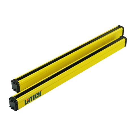
LNTECH SLA-3 User manual

SLA-3 Bending Machine Protection Device
Instruction Manual
SHANDONG LAIEN OPTIC-ELECTRONIC TECHNOLOGY CO.,LTD.


Contents
1 Basic Introduction
1.1 Summary ………………………………………………………………… 1
1.2 Manual Composition ………………………………………………… 1
1.3 Standards ……………………………………………………………… 1
1.4 Safety Signs Instruction ……………………………………………… 2
1.5 Cautions ………………………………………………………………… 2
1.6 Application Guide ……………………………………………………… 3
2 Important Information
2.1 Terminology……………………………………………………………… 5
2.2 Usage …………………………………………………………………… 6
2.3 Technical Parameters…………………………………………………… 7
2.4 Characteristics ………………………………………………………… 8
2.5 Working Modes………………………………………………………… 8
3 Components
3.1 External Size……………………………………………………………11
3.2 Parts Instruction…………………………………………………………12
3.3 Receiver Indicators……………………………………………………12
4 Installation
4.1 Safety Distance ……………………………………………………… 14
4.2 Beam Position ………………………………………………………… 15
4.3 Speed Change Point ………………………………………………… 15

Contents
4.4 Installation Postion …………………………………………………… 16
4.5 Installation Instruction ………………………………………………… 18
4.6 Installation Tools ……………………………………………………… 21
5 Wiring
5.1 Cautions ……………………………………………………………… 22
5.2 Wiring with Safety Relay ……………………………………………… 23
5.3 I/O Wiring ……………………………………………………………… 24
5.4 Signal Cable ………………………………………………………… 25
6 Debugging
6.1 Debug……………………………………………………………………26
6.2 Safety Test ………………………………………………………………27
7 Checkout and Maintenance
7.1 Cautions …………………………………………………………………29
7.2 Checkout Schedule ……………………………………………………29
8 Troubleshooting …………………………………………… 30

1
1 Important Information
1.1 Summary
1.2 Composition
This manual is composed of the SLA-3 device's instruction, operation,
installation, wiring, maintenance and troubleshooting etc. excludes the
operation instruction for the machine protected(installed with SLA-3),
please refer to the manual from the machine protected manufacturer
This manual contains chapters:
Important information contains emphasis information,the makeup of
this manual,control dependability information,certicate,directive and
so on.
Basic introduction contains the usage,features, working schematic
drawing and terminology,technical parameter data and specication of
the SLA-3 device
Cautions for installation of the SLA-3 device contains calculating
determination of placement position and attentions for neighboring
placement.
The device's function and external size.
NPN/PNP output wiring,the wiring with safety relay and so on.
Debugging
Checkout and Maintenance
Troubleshooting
1.3 Applicable Standards
Standards Title
EN 61496-1-2013 Machinery safety-Electro-sensitive protective
equipment-Part 1:General requirements and tests
EN 61496-2-2013
Machinery safety-Electro-sensitive protective
equipment-Part 2:Active opto-electronic protective
devices
EN ISO 13849-1-2008 Safety of machinery -- Safety-related parts of control
systems -- Part 1: General principles for design

2
1.4 Safety Signs
1.5 Notes
1. Read manual
Please take note of the contents marked includes the
peroper operation instructions, taken as the important components
for SLA-3 device, ensure of the manual placed at right place.
2. Operator Ability
To carry out the installtion,adjustment and maintenance by the
qualied person
3. Warning
SLA-3 can't be used with any machine that ejects materials
or components parts through the dened area, and can't
prevent the materials ejected leading to the injury.
Also can't provide the protection for below situation:
Failure to follow the instruction may result in a
serious injury or death
GB 28240-2012 Shears—Safety requirements
GB 28243-2012 Hydraulic press brakes—Safety requirements
GB 7247.1-2001 Safety of laser products--Part 1:Equipment
classication,requirements and users guide
GB 4208-2008 Degrees of protection provided by enclosure(IP code)
Failure to follow the instruction may lead to minor or
moderate injury

3
1.6 Application Cautions
1. All the upper tools come with the same height and bending middle
center, the falling prevention equipment need to be mounted on the
worktable or upper tools
2. The SLA-3 is not used to monitor two bending machines placed in a
horizontal plane
3. If the workpiece block the light beams, SLA-3 stop immediately
the press closing, meanwhile any wavy material maybe cause the
unexpected lockout, so need mute the SLA-3 before materail interrupt
the beams. i.e. when the upper tool approaching the materail at 6-15mm
(as per bending machine overstroke) , control system should send
out the muting signal to SLA-3 receiver, and ensure the closing speed
<10mm/s according to the type 4 standards.
● SLA-3 offers complete protection (nger and hands) from rapid
intervention shortly before the press closes completely, during the very
short time before complete closing with non protection, at the same time
SLA-3 function is muted(muting indicator ON)
● The switch keys should be kept by the designated person, and to
select the working modes according to the application requirements
● The protection function can't be performed to the bending machine
with press closing only at working speed, or too long overrun distance
● Prevent the SLA-3 device falling down

4
1. Must keep a certain distance between the SLA-3 beams and
upper tool, the distance referring to overrun distance measuring
value and distance of SLA-3 beam to upper tool
2. After installtion, only allowed to change the mould which has the
same overrun distance, otherwise need re-adjust SLA-3 installation
position
3. SLA-3 used with PLC, PLC monitors related short circuited and
bypass state, provides closing signal and return signal, also process
the SLA-3 output OSSD1 and OSSD2
4. Installation and connection follow the instruction manual, complte
the safety regulations to ensure safety operation, not any change
allowed to circuit which will cause protection failure.
4. SLA-3 special mode enables the bending or wavy material or even
edge bending within a closed box. If the bending machine only closes at
work speed,or too big excess of stroke, SLA-3 won't provide protection,
i.e. won't prevent access to the hazardous area.
5. The bending machine control system must meet type 4 standards
requirements.
6. The protected machine must detect the danger status, and stop it
7. The laser beam maybe intervened by airow, cause the unexpected
lockout, so guarantee the workplace without airow or little.

5
2.Basic Instruction
2.1 Terminology
Electro-sensitive protective equipment (ESPE)
Assembly of devices and components working together for protective
tripping or presence-sensing purposes and comprising as a minimum.
Detection Capability
Sensing function parameter limit specied by the supplier that will cause
actuation of the electro-sensitive protective equipment(ESPE).
EDM:
Means by which the electro-sensitive protective equipment(ESPE)
monitors the state of control devices which are external to the ESPE.
Lockout Condition:
Condition, initiated by a fault, preventing normal operation of the electro-
sensitive protective equipment(ESPE). All output signal switching
devices(OSSDs) and, where applicable, all secondary switching
devices(SSDs) are signalled to go to the OFF-state.
Muting:
Temporary automatic suspension of a safety function(s) by safety-
related parts of the control system.
On-state
State in which the output circuit is complete and permits the ow of
current.
Response Time:
Maximum time between the occurrence of the event leading to the
actuation of the sensing device and the output signal switching
devices(OSSD) achieving the OFF-state.
Fault:
State of an item characterized by inability to perform a required function,
excluding the inability during preventive maintenance or other planned
actions, or due to lack of external resources.
Performance Level(PL e):
SLA-3 device comply with EN ISO 13849 PL e requirements,i.e. EN954
cat.4 requirements.

6
Failure:
Termination of the ability of an item to perform a required function
Note 1: After failure the item has a fault
Note 2: "Failure" is an event, as distinguished from"fault", which is a state.
Note 3: This concept, as dened, does not apply to items consisting of software only.
Note 4: In practice,the term fault and failure are often used synonymously
Self-checking:
The device switches automatically into the "safe state" when it is faulty.
Standard Mounting Range:
Maximum distance between transmitter and receiver is 5 m, if exceed
the distance may lead to hazardous motion. For longer range please get
in contact with us.
Overrun Distance:
The distance covered during the overrun (e.g. by the ram of a press).
Start Interlock:
After initial operation or after a power supply interruption a renewed
"enabling" is blocked by the start interlock.The renewed release of the
switching unit is only possible by closing and opening of the start entry.
Box Bending Mode:
The E3 is muted during during bending process.
2.2 Usage
SLA-3 is the safety device specially applied to bending machine for
operator's protection which adpoted class 1 laser, A three-dimension
laser protective eld between the emitter and receiver to form the
guarding area underneath the clamped upper tool, any intervention into
the area shuts down the closing movement of the press.

7
2.3 Technical Parameters
Performance Characteristics;
Protection distance 0~20000mm
Laser source Class I,635nm
Angle of divergence ≤1.5mrad
Output PNP×2,cross check,short protection
Switch capability ≤200mA
Response time <5ms
Safety level Cat4. PL e
Anti-vibration
EN 60068-2-6
Frequency:10 ~55Hz
Amplitude:0.35mm
Protection level IP65
Protection category III
Electrical Characteristics
Power supply DC24V
Volt tolerance ±10%
Power consumption <10W
Environmental/Physical Characteristics
Operation temperature -10~50℃
Storage temperature -40 ~85℃

8
2.4 Characterisitcs
◆Floating mount to provide protection without dead zone
◆Class 1 laser can detect 4mm and vibration deviation allowed
◆Redundancy design,double outputs
◆EDM function, monitor dual valves
◆Adustment mode, aligment with ease
◆Flat bending mode, Box bending mold, Special mode, suitable
for different shape process
◆Operate at high speed, max. safety at maximum productivity
◆Samll size, simple&easy adjustment
◆Comply with EN 61496-1/-2, EN ISO13849
2.5 Working Modes
When power up the protector, keep the foot pedal in releasing condition,
press the "Mode" button to change the operation modes:"adjustment
mode","normal mode","box bending mode","special mode" which will be
indicated in receiver panel by LEDs ON.
Note: To switch the working mode is prohibited during operating the
bending machine, must remove the key after changing the mode.

9
【Adjustment Mode】
This mode applied to the condition that initially install the SLA-3 or
move the emitter/receiver in operation, all laser beams turn ON, output
OSSD1,OSSD2 turn OFF, when the beams are not aimed at the
receiver properly, E1,E2,E3 indicators "ON", otherwise the indicators
are "OFF" and no ashing means promper alignment.
【Flat Bending Mode】
Process the at material in the mode, E1,E2,E3 beams all work
normally, when any beam is blocked the output OSSD1,OSSD2 "OFF"
during the high speed closing.
Mode Change Access(key)
Mode Option Button
back of receiver
Fig.2-1 Time Diagram of Flat Bending Mode

10
【Box Bending Mode】
Under the mode,E1,E2 beams work normally, E3 beam is muted(no
protection), E1,E2 any beam is blocked during high speed closing,
output OSSD1,OSSD2 "OFF" (stop signal)
Note: if the E3 beam blocked can't be detected during high-speed
press closing twice, SLA-3 will be automatically switched into the
mode
【Special Mode】
Select the mode to process wavy material, E1,E2,E3 beams work
normally, when the beam is blocked by material during fast speed
closing, output OSSD1,OSSD2 "OFF", release and step the pedal
again, if the beam is still interrupted, output OSSD1,OSSD2 keep
"OFF", the sensor outputs the complusory slow speed signal(PNP),
control the bending machine press close at low speed <10mm/s. At
the same time SLA-3 on longer provides the protection to operator,
even though the bending machine closes at slow speed, may result in
a potential dangerous condition, so must carefully and thoughtfully use
the mode, In no event shall SHANDONG LAIEN OPTIC-ELECTRONIC
TECHNOLOGY CO.,LTD. be liable to any incidental or special damages
under the mode.
Fig.2-2 Time Diagram of Box Bending Mode

11
3.Components
3.1 External Size
Fig.3-1 External Size
Fig.2-3 Time Diagram of Special Mode
Note: Emitter external size is same as the receiver

12
Fig.3-2 SLA-3 Parts
12
34
56
3.3 Receiver Indicators
3.2 Parts Instruction
1.Emitter Front Cover
2.Receiver Front Cover
3.Emitter Back Cover
4.Receiver Back Cover
5.Emitter Panel
6.Receiver Panel

13
Mark Function Instruction Remark
E1/E2/E3
Woring status: proper alignment,
indicators (green LED) ONAdjustmen
mode: proper alignment, indicators
(green LED) OFF
Muting
indication
Receiver is muted,indicator(yellow)
asing
Power Power on, indicator(red) ON
Fault
indicator
Wrong wiring or receiver fault, indicator
(yellow) ashing
refer to
troubleshooting
Pedal switch Pedal connection,indicatro(green) ON
Slow speed
close
Low speed signal connection, indicator
(green) ON
OSSD1 Receiver output signal connection,
indicator (greeen) ON Safety output
OSSD2 Receiver output signal connection,
indicator (greeen) ON Safety output
Slow speed
clos output
Compulsory low speed output(special
mode PNP output), indicator(green) ON
Auxiliary
output
Auxiliary indication and EDM
off,indicator(green) ON
not used for
protection
Adjustment
mode
Sensors adjustment,proper alignment
indicator(green) ON
Flat bending
mode Proper alignment indicator(green) ON
Box bending
mode Proper alignment indicator(green) ON
Special mode Proper alignment,indicator(green) ON
Mode change
access
Switch to green point ON, allow to
change mode
Mode option
select mode change access at ON, then
push down the option button,can select
working mode
3.1 Receiver Indicators

14
◆To carry out the installation, connection, commissioning and
maintenance of SLA-3 device by qulied person
◆This warranty does not cover damage or liability for misuse, abuse,
or the improper application or installation
4.1 Safety Distance
The safety distance is the vertical line distance (S) from upper tool tip
to the bottom beam(E2), which is the min. distance allowed between
protection device and the dangerous area
The mounting position must be in line with the safety distance
requirements,otherwise may lead to serious injury
4 Installation(mm)
Emitter Receiver

15
safety distance(S)calculations:
● S>(t1+t2)×V+6 mm
t1: SLA-3 response time(max.5ms);
t2: bending machine stop time;
V:bending machine fast closing speed
● Determine bending machine braking distance by grating-rule, then add
6mm
Note: If different value from the calculations,take the bigger one as the
safety distance.
4.2 Light Beam Position
All beams position as following g. when SLA-3 device work's normally,
E1 beam should be positioned at 2-3mm behind the top tool tip
Fig.4-2 Light Beams Position
The point is the position from fast speed press changed to working
speed, which is calculated as per the distance from the point to the
workpiece, generally the value is set as per the machine protected
overrun distance at 6mm-15mm.
4.3 Speed Switching Point

16
Initially mount or adjust the SLA-3 position, please select the "adjustment
mode": Open the mode change access "ON", then press the mode
option button to select the "adjustment mode"
Please install the device in full compliance with the manual, otherwise
may lead to serious injury
Fig.4-4 Proper Mounting
【Installation】
The SLA-3 device bottom beam should be positioned at least 6mm on
top of the workpiece when the bending machine close at slow speed
≥ 6mm
Fig.4-3 Speed Switching Point Setting
bottom beam
4.4 Installation Position
Receiver
Emitter
Table of contents
Other LNTECH Protection Device manuals
Popular Protection Device manuals by other brands

Amina
Amina APU150 user guide

RaidSonic Technology
RaidSonic Technology ICY BOX IB-AC620-M2 Product information

FireFlex
FireFlex TOTALPAC X Owner's operation and maintenance manual

Tapeswitch
Tapeswitch PRSU/M2SI operating manual

Watts
Watts LFM116-52 Installation, operation and maintenance

GE
GE UR T60 instruction manual