Toshiba GRE110 User manual

6F2T0172
INSTRUCTION MANUAL
OVERCURRENT PROTECTION RELAY
GRE110
© TOSHIBA Corporation 2013
All Rights Reserved.
( Ver. 5.3)

6F2T0 1 7 2
Safety Precautions
Before using this product, please read this chapter carefully.
This chapter describes the safety precautions recommended when using the GRE110. Before
installing and using the equipment, this chapter must be thoroughly read and understood.
Explanation of symbols used
Signal words such as DANGER, WARNING, and two kinds of CAUTION, will be followed by
important safety information that must be carefully reviewed.
Indicates an imminently hazardous situation which will result in death or serious
injury if you do not follow the instructions.
Indicates a potentially hazardous situation which could result in death or serious
injury if you do not follow the instructions.
CAUTION Indicates a potentially hazardous situation which if not avoided, may result in
minor injury or moderate injury.
CAUTION Indicates a potentially hazardous situation which if not avoided, may result in
property damage.
DANGER
WARNING
1

6F2T0 1 7 2
•Current transformer circuit
Never allow the current transformer (CT) secondary circuit connected to this equipment to be
opened while the primary system is live. Opening the CT circuit will produce a dangerously high
voltage.
•Exposed terminals
Do not touch the terminals of this equipment while the power is on, as the high voltage generated is
dangerous.
•Residual voltage
Hazardous voltage can be present in the circuit just after switching off the power supply. It takes
approximately 30 seconds for the voltage to discharge.
CAUTION
•Earth
The earthing terminal of the equipment must be securely earthed.
CAUTION
•Operating environment
The equipment must only used within the range of ambient temperature, humidity and dust detailed
in the specification and in an environment free of abnormal vibration.
•Ratings
Before applying AC voltage and current or the power supply to the equipment, check that they
conform to the equipment ratings.
•Printed circuit board
Do not attach and remove printed circuit boards when the DC power to the equipment is on, as this
may cause the equipment to malfunction.
•External circuit
When connecting the output contacts of the equipment to an external circuit, carefully check the
supply voltage used in order to prevent the connected circuit from overheating.
•Connection cable
Carefully handle the connection cable without applying excessive force.
•Power supply
If power supply has not been supplied to the relay for two days or more, then all fault records, event
records and disturbance records and internal clock may be cleared soon after restoring the power.
This is because the back-up RAM may have discharged and may contain uncertain data.
•Modification
Do not modify this equipment, as this may cause the equipment to malfunction.
•Disposal
When disposing of this equipment, do so in a safe manner according to local regulations.
DANGER
WARNING
2

6F2T0 1 7 2
Contents
Safety Precautions 1
1. Introduction 6
2. Application Notes 8
2.1 Phase Overcurrent and Residual Overcurrent Protection 8
2.2 Instantaneous and Staged Definite Time Overcurrent Protection 16
2.3 Sensitive Earth Fault Protection 23
2.4 Phase Undercurrent Protection 34
2.5 Thermal Overload Protection 36
2.6 Negative Sequence Overcurrent Protection 38
2.7 Broken Conductor Protection 40
2.8 Breaker Failure Protection 43
2.9 Countermeasures for Magnetising Inrush 46
2.10Trip Signal Output 49
2.11Application of Protection Inhibits 51
2.12CT Requirements 53
2.13Autoreclose 55
3. Technical Description 62
3.1 Hardware Description 62
3.2 Input and Output Signals 64
3.3 Automatic Supervision 69
3.4 Recording Function 75
3.5 Metering Function 78
3.6 Control Function 78
4. User Interface 79
4.1 Outline of User Interface 79
4.2 Operation of the User Interface 82
4.3 Personal Computer Interface 150
4.4 MODBUS Interface 150
4.5 IEC 60870-5-103 Interface 150
4.6 IEC 61850 Communication 150
4.7 Clock Function 151
4.8 Special Mode 152
5. Installation 153
5.1 Receipt of Relays 153
5.2 Relay Mounting 153
3

6F2T0 1 7 2
5.3 Electrostatic Discharge 157
5.4 Handling Precautions 157
5.5 External Connections 157
5.6 Optinal case model S1-GRE110, S3-GRE110 157
6. Commissioning and Maintenance 158
6.1 Outline of Commissioning Tests 158
6.2 Cautions 158
6.3 Preparations 159
6.4 Hardware Tests 160
6.5 Function Test 162
6.6 Conjunctive Tests 172
6.7 Maintenance 174
7. Putting Relay into Service 177
Appendix A 178
Programmable Reset Characteristics and Implementation of Thermal
Model to IEC60255-149 178
Appendix B 184
Signal List 184
Appendix C 192
Event Record Items 192
Appendix D 197
Binary Output Default Setting List 197
Appendix E 200
Relay Menu Tree 200
Appendix F 211
Case Outline 211
Appendix G 214
Typical External Connection 214
Appendix H 224
Relay Setting Sheet 224
Appendix I 242
Commissioning Test Sheet (sample) 242
Appendix J 246
Return Repair Form 246
Appendix K 251
Technical Data 251
4

6F2T0 1 7 2
Appendix L 257
Symbols Used in Scheme Logic 257
Appendix M 260
Modbus: Interoperability 260
Appendix N 290
IEC60870-5-103: Interoperability 290
Appendix O 297
PLC Default setting 297
Appendix P 299
Inverse Time Characteristics 299
Appendix Q 305
IEC61850: Interoperability 305
Appendix R 347
Ordering 347
The data given in this manual are subject to change without notice. (Ver.5.3)
5

6F2T0 1 7 2
1. Introduction
GRE110 series relays provide non-directional overcurrent protection for radial distribution
Medium Voltage class networks, and back-up protection for distribution networks.
Note: GRE110 series relays are non-directional, and are applicable to systems where fault current
flows in a fixed direction, or flows in both directions but there is a significant difference in
magnitude. In systems wherea fault current flows in both directions and there is not a significant
difference in the magnitude of the fault current, the directional overcurrent protection provided
by GRE140 facilitates fault selectivity.
The GRE110 series provides the following protection schemes in all models.
•Overcurrent protection for phase and earth faults with definite time or inverse time
characteristics
•Instantaneous overcurrent protection for phase and earth faults
The GRE110 series provides the sensitive earth fault protection scheme depending on the models.
The GRE110 series provides the following functions for all models.
•Two settings groups
•Configurable binary inputs and outputs
•Circuit breaker control and condition monitoring
•Trip circuit supervision
•Autoreclosing function
•Automatic self-supervision
•Menu-based HMI system
•Configurable LED indication
•Metering and recording functions
•Front mounted USB port for local PC communications
•Rear mounted RS485 serial ports for communications
Table1.1.1 shows the members of the GRE110 series and identifies the functions to be provided by
each member.
6

6F2T0 1 7 2
Table 1.1.1 Series Members and Functions
Model Number GRE110 -
400 401 402 420 421 422 820 821
Current input 3P + E 3P + E(*) + SE 2P + Vo+ SE
Binary Input port 2 6 6 2 6 6 2 6
Binary Output port 4 4 8 4 4 8 4 4
IDMT O/C (OC1, OC2)
DT O/C (OC1 – 4)
Instantaneous O/C (OC1 – 4)
IDMT Earth Fault O/C (EF1, EF2)
DT Earth Faiult O/C (EF1 – 4)
SEF protection (SEF1 – 4)
Phase U/C
Thermal O/L
NPS O/C
Broken conductor protection
CBF protection
Inrush current detector
Cold load protection
Auto-reclose
Trip circuit supervision
Self supervision
CB state monitoring
Trip counter alarm
∑Iyalarm
CB operate time alarm
Fault records
Event records
Disturbance records
Modbus Communication
IEC60850-5-103 Communication
IEC 61850 communication (option) () ()
Case width (mm) 149 149 223 149 149 223 149 149
E: current from residual circuit or CT SE: current from core balance CT 3P: three-phase current
E(*): current (Io) calculated from three-phase current in relay internal DT: definite time
IDMT: inverse definite minimum time O/C: overcurrent protection U/C: undercurrent protection
OC∗: phase overcurrent element O/L: overload protection NPS: negative phase sequence
EF∗: earth fault element SEF: sensitive earth fault CBF: circuit breaker failure
Model 400 provides three phase and earth fault overcurrent protection.
Model 420 provides three phase, earth fault and sensitive earth fault protection.
7

6F2T0 1 7 2
2. Application Notes
2.1 Phase Overcurrent and Residual Overcurrent Protection
GRE110 provides protection for radial distribution networks with phase fault and earth fault
overcurrent elements OC1 to OC4 and EF1 to EF4*. The protection of local and downstream
terminals is coordinated with the current setting, time setting, or both.
*at model 400, 401 and 402, the earth fault current input may be connected either in the residual
circuit of the phase CTs, or alternatively a dedicated earth fault CT may be used. In the case of
connection in the residual circuit of the phase CTs, the settings of the phase CT ratio OCCT and the
earth fault CT ratio EFCT should be equal. On the other hand, where a dedicated earth fault CT is
applied, thenthe settings of OCCT and EFCT should NOT be equal, and in this case the measuring
range of earth fault current is limited to 20A maximum (see section 2.2.5).
** On GRE110-820 and 821 models, current inputs are A phase and C phase only. The B phase
element is currucurate from A phase and C phase current for metering function. But B phase
cullcurated current is not for protection and recording function. So the B phase current is not
operate at the some scheme logic.
2.1.1 Inverse Time Overcurrent Protection
In a system for which the fault current is practically determined by the fault location, without being
substantially affected by changes in the power source impedance, it is advantageous to use inverse
definite minimum time (IDMT) overcurrent protection. This protection provides reasonably fast
tripping, even at a terminal close to the power source where the most severe faults can occur.
Where ZS (the impedance between the relay and the power source) is small compared with that of
the protected section ZL, there is an appreciable difference between the current for a fault at the far
end of the section (ES/(ZS+ZL), ES: source voltage), and the current for a fault at the near end
(ES/ZS). When operating time is inversely proportional to the current, the relay operates faster for
a fault at the end of the section nearer the power source, and the operating time ratio for a fault at
the near end to the far end is ZS/(ZS + ZL).
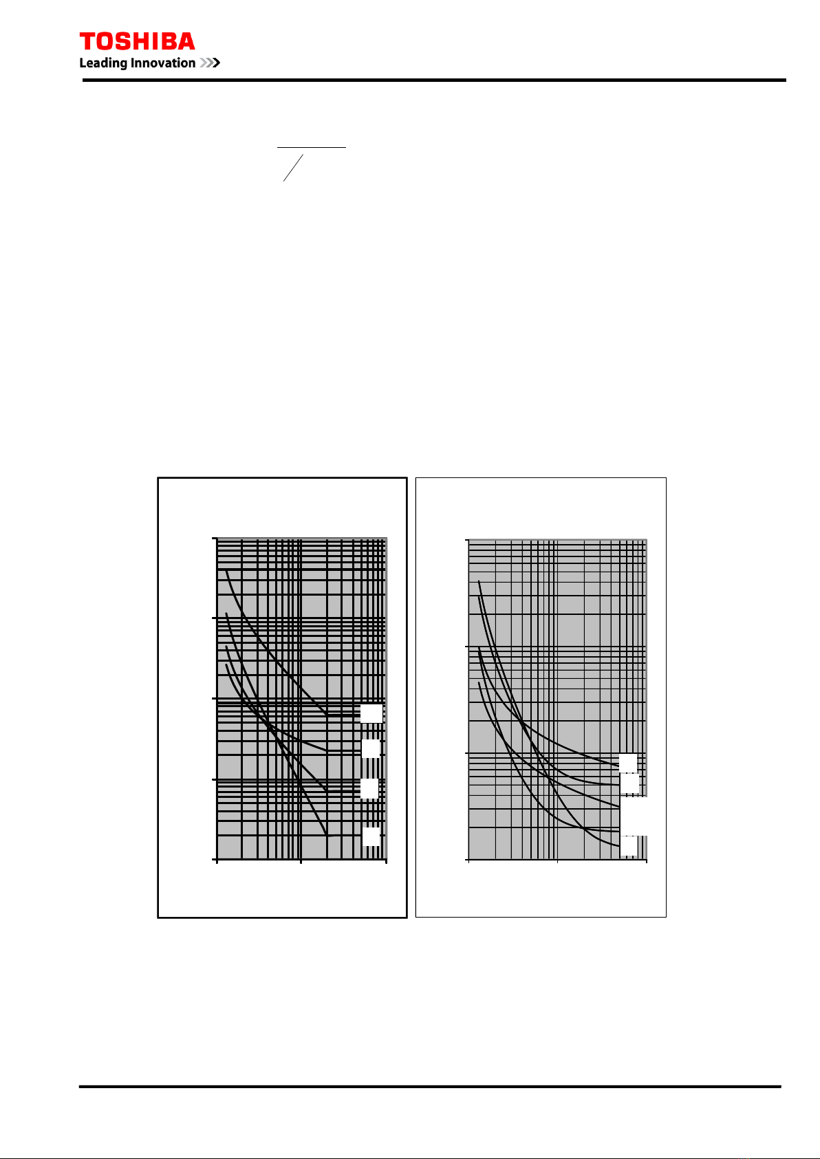
The resultant time-distance characteristics are shown in Figure 2.1.1 for radial networks with
several feeder sections. With the same selective time coordination margin TC as the downstream
section, the operating time can be further reduced by using a more inverse characteristic.
T
C
T
C
A
B
C
Operate time
Figure 2.1.1 Time-distance Characteristics of Inverse Time Protection
The OC1 and EF1 elements for stage-1 have IDMT characteristics defined by equation (1) in
accordance with IEC 60255-151:
8

6F2T0 1 7 2
( )
+
−
×= c
Is
I
k
TMS
t1
α
where:
t = operating time for constant current I (seconds),
I = energising current (amps),
Is = overcurrent setting (amps),
TMS = time multiplier setting,
k, α, c = constants defining curve.
Nine curve types are available as defined in Table 2.1.1. They are illustrated in Figure 2.1.2.
In addition to the above nine curve types, OC1 and EF1 can provide user configurable IDMT
curves. If required, set the scheme switch [M∗∗∗] to “C” and set the curve defining constants k, α
and c. The following table shows the setting ranges of the curve defining constants. OC2 and EF2
for stage-2 also provide the same inverse time protection as OC1 and EF1.
0.1
1
10
100
1000
110 100
Operating Time(s)
Current(MultipleofSetting)
IEC/UK Inverse Curves
(TimeMultiplier= 1)
LTI
NI
VI
EI
0.1
1
10
100
110 100
Operating Time (s)
Current (Multiple of Setting)
IEEE/US Inverse Curves
(Time Multiplier = 1)
MI
VI
CO2
CO8
EI
Figure 2.1.2 IDMT Characteristics
Programmable Reset Characteristics
OC1 and EF1 have a programmable reset feature: instantaneous, definite time delayed, or
dependent time delayed reset. (Refer to Appendix A for a more detailed description.)
Instantaneous resetting is normally applied in multi-shot auto-reclosing schemes, to ensure correct
(1)
9

6F2T0 1 7 2
grading between relays at various points in the scheme.
The inverse reset characteristic is particularly useful for providing correct coordination with an
upstream induction disc type overcurrent relay.
The definite time delayed reset characteristic may be used to provide faster clearance of intermittent
(‘pecking’ or ‘flashing’) fault conditions.
Definite time reset
The definite time resetting characteristic is applied to the IEC/IEEE/US operating characteristics.
If definite time resetting is selected, and the delay period is set to instantaneous, then no intentional
delay is added. As soon as the energising current falls below the reset threshold, the element returns
to its reset condition.
If the delay period is set to some value in seconds, then an intentional delay is added to the reset
period. If the energising current exceeds the setting for a transient period without causing tripping,
then resetting is delayed for a user-definable period. When the energising current falls below the
reset threshold, the integral state (the point towards operation that it has travelled) of the timing
function (IDMT) is held for that period.
This does not apply following a trip operation, in which case resetting is always instantaneous.
Dependent time reset
The dependent time resetting characteristic is applied only to the IEEE/US operate characteristics,
and is defined by the following equation:
−
×=
β
S
I
I
kr
RTMSt
1
(2)
where:
t = time required for the element to reset fully after complete operation (seconds),
I = energising current (amps),
Is = overcurrent setting (amps),
kr= time required to reset fully after complete operation when the energising current is zero
(see Table 2.1.1),
RTMS = reset time multiplier setting.
k, β, c = constants defining curve.
Figure 2.1.3 illustrates the dependent time reset characteristics.
The dependent time reset characteristic also can provide user configurable IDMT curve. If
required, set the scheme switch [M∗∗∗] to “C” and set the curve defining constants kr and β. Table
2.1.1 shows the setting ranges of the curve defining constants.
10

6F2T0 1 7 2
Table 2.1.1 Specification of IDMT Curves
Curve Description IEC ref. k αc krβ
IEC Normal Inverse A 0.14 0.02 0 - -
IEC Very Inverse B 13.5 1 0 - -
IEC Extremely Inverse C 80 2 0 - -
UK Long Time Inverse - 120 1 0 - -
IEEE Moderately Inverse D 0.0515 0.02 0.114 4.85 2
IEEE Very Inverse E 19.61 2 0.491 21.6 2
IEEE Extremely Inverse F 28.2 2 0.1217 29.1 2
US CO8 Inverse - 5.95 2 0.18 5.95 2
US CO2 Short Time Inverse - 0.02394 0.02 0.01694 2.261 2
User configurable curve - 0.00 –
300.00 0.00 –
5.00 0.000 –
5.000 0.00 –
300.00 0.00 –
5.00
Note: kr and βare used to define the reset characteristic. Refer to equation (2).
IEEE Reset Curves
(Time Multiplier = 1)
1.00
10.00
100.00
1000.00
0.1 1
Current (Multiple of Setting)
Time (s)
MI
VI
EI
CO2
CO8
Figure 2.1.3 Dependent Time Reset Characteristics
2.1.2 Definite Time Overcurrent Protection
In a system in which the fault current does not vary a great deal in relation to the position of the
fault, that is, the impedance between the relay and the power source is large, the advantages of the
11

6F2T0 1 7 2
IDMT characteristics are not fully utilised. In this case, definite time overcurrent protection is
applied. The operating time can be constant irrespective of the magnitude of the fault current.
The definite time overcurrent protection consists of instantaneous overcurrent measuring elements
OC1 and EF1 and delayed pick-up timers started by the elements, and provides selective protection
with graded setting of the delayed pick-up timers. Thus, the constant time coordination with the
downstream section can be maintained as shown in Figure 2.1.4 As is clear in the figure, the nearer
to the power source a section is, the greater the delay in the tripping time of the section. This is
undesirable particularly where there are many sections in the series.
Operate time
T
C
T
C
A
B
C
Figure 2.1.4 Definite Time Overcurrent Protection
2.1.3 Scheme Logic
Figure 2.1.5 and Figure 2.1.6 show the scheme logic of the phase fault and earth fault overcurrent
protection with selective definite time or inverse time characteristic.
The definite time protection is selected by setting [MOC1] and [MEF1] to “D”. Definite time
overcurrent elements OC1-D and EF1-D are enabled for phase fault and earth fault protection
respectively, and trip signal OC1 TRIP and EF1 TRIP are given through the delayed pick-up timer
TOC1 and TEF1.
The inverse time protection is selected by setting [MOC1] and [MEF1] to either “IEC”, “IEEE” or
“US” according to the IDMT characteristic to employ. Inverse time overcurrent elements OC1-I
and EF1-I are enabled for phase fault and earth fault protection respectively, and trip signal OC1
TRIP and EF1 TRIP are given.
ICD is the inrush current detector ICD, which detects second harmonic inrush current during
transformer energisation etc. , and can block the OC1-D element by the scheme switch [OC1-2F]
respectively. See Section 2.9.
The signals OC1 HS and EF1 HS are used for blocked overcurrent protection and blocked busbar
protection (refer to Section 2.12).
These protections can be disabled by the scheme switches [OC1EN] and [EF1EN] or binary input
signals OC1 BLOCK and EF1 BLOCK.
OC2 and EF2 are provided with the same logic of OC1 and EF1.
12

6F2T0 1 7 2
≥1
OC1 TRIP
OC1 BLOCK
1
0.00 -300.00s
&
TOC1
t
0
"IEC"
"IEEE"
+
"ON"
[OC1EN
+
C
B
A
OC1
-D
&
t
0
≥1
&
t
0
≥1
&
C
B
A
&
&
"US"
"C"
≥1
≥1
≥1
&
≥1
102
OC1-A TRIP
103
104
101
OC1-B TRIP
OC1-C TRIP
51
OC1-A
52
53
OC1-B
OC1-C
"D"
OC1
-I
&
[MOC1]
+
[OC1-2F]
ICD
“Block”
C
B
A
OC1
HS
OC1-A HS
88
OC1-B HS
89
OC1-C HS
90
Figure 2.1.5 Phase Fault Overcurrent Protection OC1
EF1-D
≥1
EF1 TRIP
&
0.00 - 300.00s
TEF1
t
0
EF1-I
EF1 BLOCK
1
"ON"
[EF1EN]
+
&
"D"
[MEF1]
"IEC"
"IEEE"
+
"US"
"C"
&
≥1
117
63
EF1
&
ICD
“Block”
+
[EF1-2F]
EF1HS
EF1 HS
91
Figure 2.1.6 Earth Fault Overcurrent Protection EF1
13

6F2T0 1 7 2
2.1.4 Settings
The table shows the setting elements necessary for the phase and residual overcurrent protection
and their setting ranges.
Element Range Step Default Remarks
OCCT 1 - 20000 1 400 CT ratio for 3-phase current
EFCT 1 - 20000 1 200 CT ratio for earth-fault curret
OC1 0.10 – 25.00 A 0.01 A 1.00 A OC1 threshold setting
TOC1 0.010 – 1.500 0.001 1.000 OC1 time multipliersetting. Required if [MOC1] =
IEC, IEEE, US or C.
0.00 – 300.00 s 0.01 s 1.00 s OC1 definite time setting. Required if [MOC1] =
DT.
TOC1R 0.0 – 300.0 s 0.1 s 0.0 s OC1 definite time delayed reset. Required if
[MOC1] = IECorif [OC1R] = DEF.
TOC1RM 0.010 – 1.500 0.001 1.000 OC1dependenttimedelayedresettimemultiplier.
Required if [OC1R] = DEP.
EF1 0.05 – 25.00 A 0.01 A 0.30 A EF1 threshold setting
TEF1 0.010 – 1.500 0.001 1.000 EF1 time multiplier setting. Required if [MEF1] =
IEC, IEEE, US or C.
0.00 – 300.00 s 0.01 s 1.00 s EF1definitetimesetting.Requiredif[MEF1]=DT.
TEF1R 0.0 – 300.0 s 0.1 s 0.0 s EF1 definite time delayed reset. Required if
[MEF1] = IEC orif [EF1R] =DEF.
TEF1RM 0.010 – 1.500 0.001 1.000 EF1 dependent time delayed reset time multiplier.
Required if [EF1R] = DEP.
[OC1EN] Off / On On OC1 Enable
[MOC1] D / IEC / IEEE / US / C D OC1 characteristic
[MOC1C]
MOC1C-IEC
MOC1C-IEEE
MOC1C-US
NI / VI / EI / LTI
MI / VI / EI
CO2 / CO8
NI
MI
CO2
OC1 inverse curve type.
Required if [MOC1] = IEC.
Required if [MOC1] = IEEE.
Required if [MOC1] = US.
[OC1R] DEF / DEP DEF OC1 reset characteristic. Required if [MOC1] =
IEEE or US.
[OC1-2F] NA / Block NA OC1 2f block Enable
[EF1EN] Off / On On EF1 Enable
[MEF1] D / IEC / IEEE / US / C D EF1 characteristic
[MEF1C]
MEF1C-IEC
MEF1C-IEEE
MEF1C-US
NI / VI / EI / LTI
MI / VI / EI
CO2 / CO8
NI
MI
CO2
EF1 inverse curve type.
Required if [MEF1] = IEC.
Required if [MEF1] = IEEE.
Required if [MEF1] = US.
[EF1R] DEF / DEP DEF EF1 reset characteristic. Required if [MEF1] =
IEEE or US.
[EF1-2F] NA / Block NA EF1 2f block Enable
14

6F2T0 1 7 2
Settings for Inverse Time Overcurrent protection
Current setting
In Figure 2.1.7, the current setting at terminal A is set lower than the minimum fault current in the
event of a fault at remote end F1. Furthermore, when also considering backup protection for a fault
on the next feeder section, it is set lower than the minimum fault current in the event of a fault at
remote end F3.
To calculate the minimum fault current, phase-to-phase faults are assumed for the phase
overcurrent element, and phase to earth faults for residual overcurrent element, assuming the
probable maximum source impedance. When considering the fault at F3, the remote end of the next
section is assumed to be open.
The higher the current setting, the more effective the inverse characteristic. On the other hand, the
lower the setting, the more dependable the operation. The setting is normally 1 to 1.5 times or less
of the minimum fault current.
For grading of the current settings, the terminal furthest from the power source is set to the lowest
value and the terminals closer to the power source are set to a higher value.
The minimum setting of the phase overcurrent element is restricted so as not to operate for the
maximum load current, and that of the residual overcurrent element is restricted so as to not operate
on false zero-sequence current caused by an unbalance in the load current, errors in the current
transformer circuits, or zero-sequence mutual coupling of parallel lines.
F3
F2
F1
C
B
A
Figure 2.1.7 Current Settings in Radial Feeder
Time setting
Time setting is performed to provide selectivity in relation to the relays on adjacent feeders.
Consider a minimum source impedance when the current flowing through the relay reaches a
maximum. In Figure 2.1.7, in the event of a fault at F2, the operating time is set so that terminal A
may operate by time grading Tc behind terminal B. The current flowing in the relays may
sometimes be greater when the remote end of the adjacent line is open. At this time, time
coordination must also be kept.
The reason why the operating time is set when the fault current reaches a maximum is that if time
coordination is obtained for a large fault current, then time coordination can also be obtained for the
small fault current as long as relays with the same operating characteristic are used for each
terminal.
The grading margin Tc of terminal A and terminal B is given by the following expression for a fault
at point F2 in Figure 2.1.7.
Tc= T1+ T2+ Tm
where, T1:circuit breaker clearance time at B
T2: relay reset time at A
Tm: time margin
15

6F2T0 1 7 2
Settings of Definite Time Overcurrent protection
Current setting
The current setting is set lower than the minimum fault current in the event of a fault at the remote
end of the protected feeder section. Furthermore, when also considering backup protection for a
fault in a next feeder section, it is set lower than the minimum fault current, in the event of a fault at
the remote end of the next feeder section.
Identical current values can be set for terminals, but graded settings are better than identical
settings, in order to provide a margin for current sensitivity. The farther from the power source the
terminal is located, the higher the sensitivity (i.e. the lower setting) that is required.
The minimum setting of the phase overcurrent element is restricted so as not to operate for the
maximum load current, and that of the residual overcurrent element is restricted so as to not operate
on false zero-sequence current caused by an unbalance in the load current, errors in the current
transformer circuits, or zero-sequence mutual coupling of parallel lines. Taking the selection of
instantaneous operation into consideration, the settings must be high enough not to operate for large
motor starting currents or transformer inrush currents.
Time setting
When setting the delayed pick-up timers, the time grading margin Tc is obtained in the same way as
explained in “Settings for Inverse Time Overcurrent Protection”.
2.2 Instantaneous and Staged Definite Time Overcurrent Protection
In conjunction with inverse time overcurrent protection, definite time overcurrent elements OC2 to
OC4 and EF2 to EF4 provide instantaneous overcurrent protection. OC2 and EF2 also provide the
same inverse time protection as OC1 and EF1.
OC2 to OC4 and EF2 to EF4 are phase fault and earth fault protection elements, respectively. Each
element is programmable for instantaneous or definite time delayed operation. The phase fault
elements operate on a phase segregated basis, although tripping is for three phase only.
2.2.1 Selective Instantaneous Overcurrent Protection
When they are applied to radial networks with several feeder sections where ZL (impedance of the
protected line) is large enough compared with ZS (the impedance between the relay and the power
source), and the magnitude of the fault current in the local end fault is much greater (3 times or
more, or (ZL+ZS)/ZS≧3, for example) than that in the remote end fault under the condition that
ZS is maximum, the pick-up current can be set sufficiently high so that the operating zone of the
elements do not reach the remote end of the feeder, and thus instantaneous and selective protection
can be applied.
This high setting overcurrent protection is applicable and effective particularly for feeders near the
power source where the setting is feasible, but the longest tripping times would otherwise have to be
accepted.
As long as the associated inverse time overcurrent protection is correctly coordinated, the
instantaneous protection does not require setting coordination with the downstream section.
Figure 2.2.1 shows operating times for instantaneous overcurrent protection in conjunction with
inverse time overcurrent protection. The shaded area shows the reduction in operating time by
applying the instantaneous overcurrent protection. The instantaneous protection zone decreases as
ZS increases.
16

6F2T0 1 7 2
T
C
T
C
A
B
C
Operate time
Figure 2.2.1 Conjunction of Inverse and Instantaneous Overcurrent Protection
The current setting is set 1.3 to 1.5 times higher than the probable maximum fault current in the
event of a fault at the remote end. The maximum fault current for elements OC2 to OC4 is obtained
in case of three-phase faults, while the maximum fault current for elements EF2 to EF4 is obtained
in the event of single phase earth faults.
2.2.2 Staged Definite Time Overcurrent Protection
When applying inverse time overcurrent protection for a feeder system as shown in Figure 2.2.2,
well coordinated protection with the fuses in branch circuit faults and high-speed protection for the
feeder faults can be provided by adding staged definite time overcurrent protection with
time-graded OC2 and OC3 or EF2 and EF3 elements.
Fuse
GRE110
Figure 2.2.2 Feeder Protection Coordinated with Fuses
Configuring the inverse time element OC1 (and EF1) and time graded elements OC2 and OC3 (or
EF2 and EF3) as shown in Figure 2.2.3, the characteristic of overcurrent protection can be
improved to coordinate with the fuse characteristic.
17

6F2T0 1 7 2
Current (amps)
Time (s)
OC2
OC3
Fuse
OC1
Figure 2.2.3 Staged Definite Time Protection
2.2.3 Scheme Logic
As shown in Figure 2.2.4 to Figure 2.2.9, OC2 to OC4 and EF2 to EF4 have independent scheme
logics. OC2 and EF2 provide the same logic of OC1 and EF1. OC3 and EF3 give trip signals OC3
TRIP and EF3 TRIP through delayed pick-up timers TOC3 and TEF3. OC4 and EF4 are used to
output alarm signals OC4 ALARM and EF4 ALARM. Each trip and alarm can be blocked by
incorporated scheme switches [OC2EN] to [EF4EN] and binary input signals OC2 BLOCK to EF4
BLOCK. OC*-D and EF*-D elements can be also blocked by the scheme switches [OC*-2F] and
[EF*-2F]. See Section 2.9.
≥1
OC2 TRIP
OC2BLOCK
1
0.00 -300.00s
&
TOC2
t
0
"IEC"
"IEEE"
+
"ON"
[OC2EN
+
C
B
A
OC2
-D
&
t
0
≥1
&
t
0
≥1
&
C
B
A
&
&
"US"
"C"
≥1
≥1
≥1
&
≥1
106
OC2-A TRIP
107
108
105
OC2-B TRIP
OC2-C TRIP
54
OC2-A
55
56
OC2-B
OC2-C
"D"
OC2
-I
&
[MOC2]
+
[OC2-2F]
ICD
“Block”
Figure 2.2.4 Phase Overcurrent Protection OC2
18

6F2T0 1 7 2
C
B
A
OC3
0.00 - 300.00s
&
&
TOC3
t
0
t
0
t
0
&
OC3 TRIP
OC3-A TRIP
OC3-B TRIP
OC3-C TRIP
≥1
OC3 BLOCK
1
"ON"
[OC3EN]
+
&
110
111
112
57
58
59
109
+
&
[OC3-2F]
ICD
“Block”
Figure 2.2.5 Phase Overcurrent Protection OC3
C
B
A
OC4
0.00 - 300.00s
&
&
TOC4
t
0
t
0
t
0
&
OC4
ALARM
OC4-A
ALARM
OC4-B
ALARM
OC4-C
ALARM
≥1
OC4 BLOCK
1
"ON"
[OC4EN]
+
&
114
115
116
60
61
62
113
+
&
[OC4-2F]
ICD
“Block”
Figure 2.2.6 Phase Overcurrent Protection OC4
EF2-D
≥1
EF2 TRIP
&
0.00 - 300.00s
TEF2
t
0
EF2-I
EF2 BLOCK
1
"ON"
[EF2EN]
+
&
"D"
[MEF2]
"IEC"
"IEEE"
+
"US"
"C"
&
≥1
118
64
EF1
&
ICD
“Block”
+
[EF2-2F]
Figure 2.2.7 Earth fault Protection EF2
19
Table of contents
Other Toshiba Protection Device manuals
Popular Protection Device manuals by other brands

OBO Bettermann
OBO Bettermann PDP-2-48-D Mounting instructions

AGF
AGF COLLECTanDRAIN 5400 owner's manual

DIADEM
DIADEM DiaSafe Single Technical manual

FireFlex
FireFlex TOTALPAC X Owner's operation and maintenance manual

Scorpion Power System
Scorpion Power System Tribunus 06-120A ESC user guide

Guardian
Guardian MEDIFONE Quick start user guide