Loadrite Sprint User manual

Weighing System
MANUAL
OPERATORS


Sprint Weighing System
Model LR911
Document No. MAN-80505-04
Software No. 60187 Version 2.0
Issue Date: March 2003
Distributed Worldwide by:
)93 First Avenue, PO Box 13-115, Tauranga, New Zealand
+64-7-5776034
℡+64-7-5782820
www.loadritescales.com
Designed & Manufactured by:
)8 Walls Road, PO Box 12-607, Penrose, Auckland, New Zealand
www.actronic.com
This manual is copyrighted with all rights reserved. Under copyright laws, this manual may not be
copied in whole or in part or reproduced in any other media without the express written permission
of Actronic Ltd. Permitted copies must carry the same proprietary and copyright notices as were
affixed to the original. Under the law, copying includes translation into another language.
Please note that while every effort has been made to ensure that the data given in this document is
accurate, the information, figures, illustrations, tables, specifications, and schematics contained
herein are subject to change without notice.
Actronic Ltd assumes no liability in connection with the use of any Loadrite branded product.
© 2003 ACTRONIC LIMITED


i
Contents
1 Introduction..................................................................................................................................1
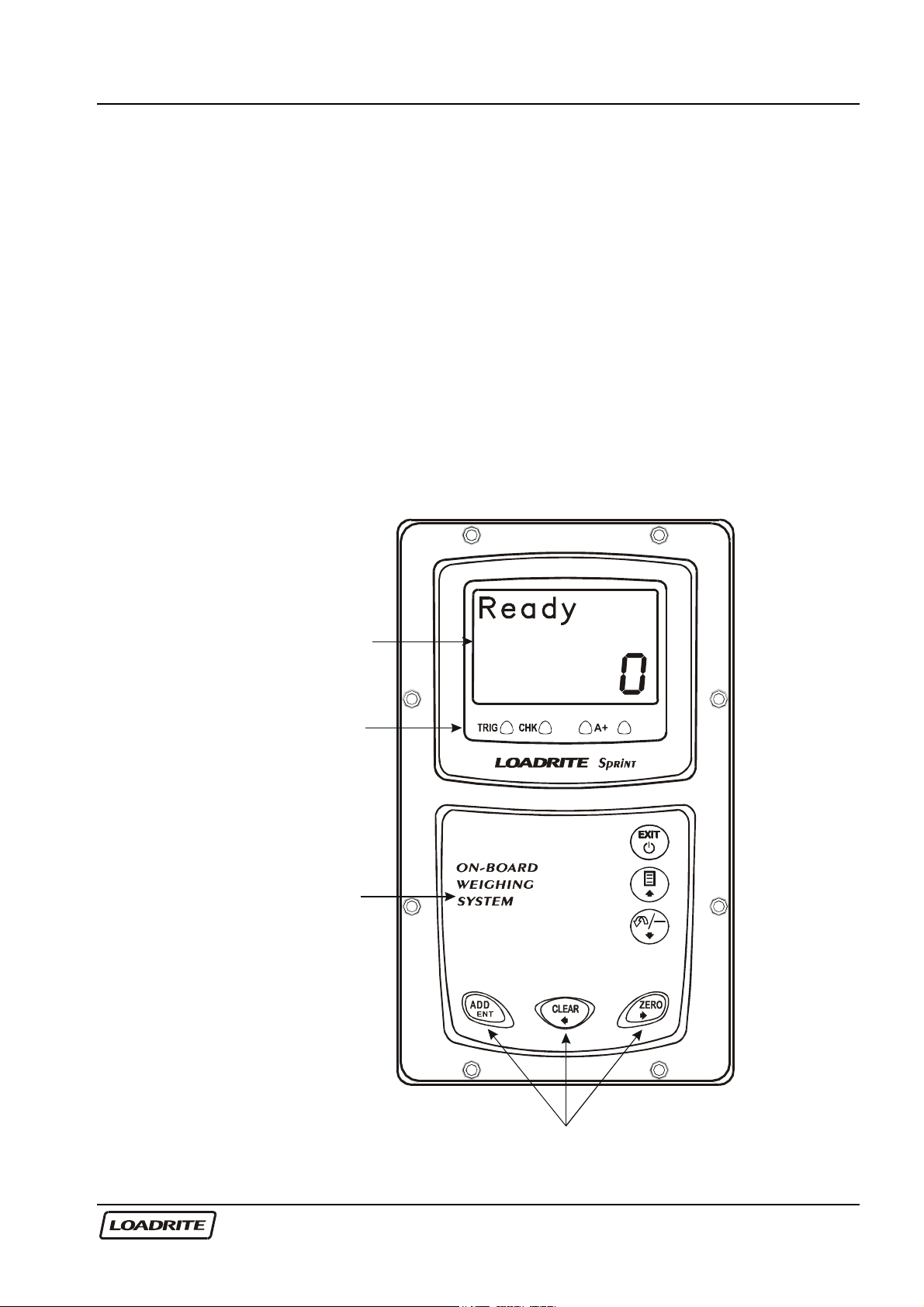
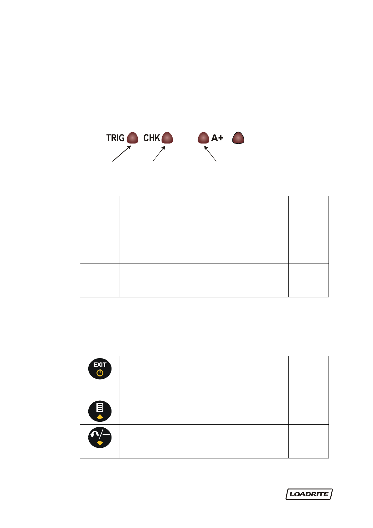
Indicator Lights .............................................................................................................................................. 2
Keypad ............................................................................................................................................................ 2
2 Quick Start Guide........................................................................................................................4
Switching On ................................................................................................................................................. 4
Standby............................................................................................................................................................ 4
The Warm Up Screen .................................................................................................................................. 4
The Ready Screen ......................................................................................................................................... 5
Weighing a Load ........................................................................................................................................... 5
Static Weigh function................................................................................................................................... 6
Adding a Load ............................................................................................................................................... 6
Clearing the Short Total............................................................................................................................... 7
Zeroing............................................................................................................................................................ 7
3 Weighing Overview .....................................................................................................................9
Weighing Mode ............................................................................................................................................ 9
Short and Long Totals .................................................................................................................................. 9
Accurate Weighing....................................................................................................................................... 9
General Method of Weighing..................................................................................................................10
4 Weighing Procedures ................................................................................................................11
Adding a Load .............................................................................................................................................11
Auto-Add.......................................................................................................................................................11
Subtracting a Load......................................................................................................................................12
Zeroing..........................................................................................................................................................13
Recalling Last Load .....................................................................................................................................15
Viewing Long Total.....................................................................................................................................16
Clearing Totals .............................................................................................................................................16
5 Menu Options ............................................................................................................................18
Setup..............................................................................................................................................................18
Clock Setting (Clock) ................................................................................................................................19
Changing Scale Number (Scale#) ..........................................................................................................19
Long Total (Long Tot).................................................................................................................................20
Auto Add On/Off Setting (Auto Add)....................................................................................................21
Rotary Trigger Position Screen (TrigScrn)..............................................................................................21
LD941 Data Module Properties (Module)...........................................................................................22
Internal Buffer Usage (Usage)..................................................................................................................22
Internal Buffer Reset (Reset).....................................................................................................................22
Self Test (Selftest).......................................................................................................................................23
Uplink (Uplink) ............................................................................................................................................23
6 Print Functions ...........................................................................................................................24
Printed Data .................................................................................................................................................24
7 Obtaining the Best Accuracy ...................................................................................................25
Lifting Speed.................................................................................................................................................25
Trigger Point.................................................................................................................................................25
Bounce ..........................................................................................................................................................25
Centre of Gravity ........................................................................................................................................25

ii
8 Error Messages .......................................................................................................................... 26
Check Power................................................................................................................................................26
Check Transducer .......................................................................................................................................26
Check Trigger...............................................................................................................................................26
Check Zero...................................................................................................................................................26
Lift Under Range .........................................................................................................................................26
Module Data Lost .......................................................................................................................................26
Module Error ................................................................................................................................................27
Module Full...................................................................................................................................................27
No Lock.........................................................................................................................................................27
Overload .......................................................................................................................................................27
Printer Disabled ...........................................................................................................................................27
Printer Error ..................................................................................................................................................27
Recall Disabled ............................................................................................................................................27
Too Heavy, Zero Aborted.........................................................................................................................28
Warm Up Lift................................................................................................................................................28
9 Specifications............................................................................................................................. 29
10 Output / Input Connections .................................................................................................. 31
Appendix i Time and Date.......................................................................................................... 32
Appendix ii Span Calibration Adjustment ................................................................................ 35

LOADRITE SPRINT OPERATORS MANUAL
1
1 Introduction
The Loadrite Weighing System measures the weight of loads lifted by small
front-end loaders, forklift trucks and similar machines that use hydraulic
rams to lift the load. The Loadrite is installed in the cab of the loading
machine and is connected to sensors on the lifting arms.
As the machine raises the load, the Loadrite measures the hydraulic
pressure in the lift cylinders, converts pressure into a weight reading and
displays the result. An electronic trigger device mounted on the lift arms
ensures that the pressure readings are always taken at the same position
on every lift.
The weight of the bucket or forks and associated structures is zeroed out
when the system is calibrated so that only the weight of the payload is
displayed. While operating the loader, the driver can add each weight lifted
to a running total.
LCD display
Indicator lights
Keypad
Main Operating Keys

LOADRITE SPRINT OPERATORS MANUAL
2
The Loadrite has internal memory which stores settings and production data
even when switched off.
Indicator Lights
The indicator lights are provided below the LCD screen.
Trigger Check
A
uto-Add
Trigger Illuminates when a load is lifted past the trigger
point. When this light is on, the lifted weight
may be added.
Pages 5
and 10
Check
Function
Illuminates when the Loadrite is in the user-
selected function.
Configuration is set during installation.
-
Auto-Add Illuminates when the Loadrite is in Auto-Add
mode. In this mode, the Loadrite will
automatically add the lifted weight.
Page 11
Keypad
The table below shows the special functions that the keys have in addition
to their numeric values used for entering data.
Exits an operation without changing the data.
When pressed on the Ready screen, puts the
Loadrite into standby mode. To return to the
Ready screen, press any key.
Access to menu.
Scroll up.
Page 18
Subtracts the current load from the total. Recalls
the last load.
Scroll down.
Page 12
and 13

LOADRITE SPRINT OPERATORS MANUAL
3
Adds the current load to the total.
Enter key for accepting data or changes.
Page 6
and 11
Clears the short total for the current product.
Scroll left.
Page 7
and 16
Zeroes out the current load.
Scroll right.
Page 7
and 13

LOADRITE SPRINT OPERATORS MANUAL
4
2 Quick Start Guide
This section summarises the common Loadrite procedures. For full details
of weighing methods, see Chapter 3 Weighing Overview on page 9 and
Chapter 4 Weighing Procedures on page 11
Switching On
The Loadrite powers up automatically when you switch on the ignition of the
loading machine.
If the Loadrite has been switched off for more than 30 minutes, it displays
the Warm Up screen when powered up.
Standby
The Loadrite has a ‘standby’ mode which is similar to turning the Loadrite
off.
To put the Loadrite into standby press
, the EXIT key, when in the Ready
mode.
To restart the Loadrite, press any key.
Standby
The Warm Up Screen
For best weighing accuracy, the hydraulic fluid in the lift cylinders should be
at normal operating temperature. This is achieved by raising and lowering
the empty bucket or forks a few times.
The Warm up screen is displayed if the machine has been turned off over
an hour.
Raise the empty bucket or forks
past the trigger point three times. Warm up
Lift 3

LOADRITE SPRINT OPERATORS MANUAL
5
The Loadrite beeps at each lift
and displays the count down from
3. After the third lift, the Ready
screen is displayed and the
screen may look like this.
If it is time to check zero, the
Loadrite will display the Check
Zero message to remind you.
More information about Ready
screen and Check Zero screen
will be covered later in this
manual.
Ready
0
Check
Zero
The Ready Screen
The Ready screen shows the ready status and the short total. The short
total is simply the sum of loads since you last cleared the total.
When the Ready screen is displayed, the Loadrite is ready to weigh.
Ready
3400
The Loadrite is ready to weigh
Current total loaded
Weighing a Load
(Weights shown are examples only)
Loadrite is ready to
weigh sand.
(Current total 3400)
Ready
3400
Raise the load
smoothly past the
trigger point using
normal engine revs.
The bucket must be
fully rolled back
during weighing.
Weighing
3400

LOADRITE SPRINT OPERATORS MANUAL
6
A short time later,
the Loadrite beeps,
turns the TRIG
indicator light on
and displays the
load lifted (2200).
Total
3400
2200
The trigger point is where the trigger activator (e.g. the metal plate in the
optical trigger or the magnet in the magnetic trigger) passes the body of the
trigger.
Static Weigh function
The Loadrite has an option known as ‘Static Weigh’. When this is used, the
weight display is always ‘live’ and no trigger is used.
The ‘Trigger’ light is used to indicate that the weight being measured is
‘stable’ (not changing too much) and therefore can be Added, Subtracted or
Zeroed.
Your Loadrite dealer will have configured the Static Weigh function if
required.
Recall function does not work when in ‘Static Weigh’ mode – refer to page
15.
Adding a Load
(Weights shown are examples only)
Before lifting.
(Current total 5600)
Ready
5600
Raise the load smoothly past the trigger
point using normal engine revs.
The Loadrite beeps and displays the load.
(Weight of load 2200)
Total
5600
2200

LOADRITE SPRINT OPERATORS MANUAL
7
Press .
The Loadrite updates the total and returns
to the Ready state.
(New total 7800)
Ready
7800
Clearing the Short Total
When you want to reset the short total to
zero (e.g. after loading a truck) ready for
another loading operation,
Press .
Ready
7800
The Loadrite displays Total Cleared for
a few seconds, clears the short total for the
current product and then …
Total
Cleared
7800
…returns to the Ready screen. Ready
0
Zeroing
It is required to zero the Loadrite from time to time. This is to avoid
inaccurate readings due to build up of material in the bucket.
(Weights shown are examples only)
Before lifting.
Make sure that the bucket is empty and
fully rolled back.
Ready
0

LOADRITE SPRINT OPERATORS MANUAL
8
Raise the bucket smoothly past the trigger
point.
The Loadrite beeps and displays the load.
Total
0
20
Press .
The Loadrite performs the zero adjustment
and returns to the Ready state.
Ready
0
More detailed information about Zeroing can be found on page 13.

LOADRITE SPRINT OPERATORS MANUAL
9
3 Weighing Overview
Weighing Mode
While individual bucket weight can be measured, the Loadrite also has an
ability to accumulate how much weight you have loaded on to a truck. This
weighing mode is called Total mode. This is, as you add bucket loads, the
weights are added to the totals. The short total is displayed.
Short and Long Totals
The Loadrite keeps a total of the bucket weights that you add. Two
independent totals are stored.
Short Total Typically used to display the total weight loaded
onto a truck.
As you add successive loads, the Loadrite
displays the updated Short Total (sum of the
loads so far) on the Ready screen.
Long Total Typically used to accumulate the weights
loaded over a longer period, for example a shift
or a day.
Long total may be viewed via menu. See page
20.
Accurate Weighing
For accurate weighing, make sure that:
• The bucket or forks are fully rolled back for each lift.
• The loader is stationary.
• The lift arms start well below the trigger point. This ensures that all
acceleration and load bounce has been eliminated well before the
trigger sequence begins.
• The Loadrite is correctly zeroed. (Zeroing is described on page 13).

LOADRITE SPRINT OPERATORS MANUAL
10
General Method of Weighing
1. BUCKET BACK. After picking up material into the bucket, roll the
bucket back.
2. LIFT. Raise the load smoothly past the trigger point using normal
engine revs. (The trigger point is where the metal plate passes the
body of the trigger). For best results, operate the lift lever before
accelerating the engine so that the machine does not rock as it lifts.
The Loadrite beeps, turns the TRIG light on and displays the load.
(See also page 5).
3. ADD. The Loadrite waits for a few seconds for you to take one of the
following actions:
• Press to add the weight to the long and short totals, or
• Press to subtract the load from the totals, or
• Press to zero the measuring system.
If you don’t press a key, the Loadrite beeps and prompts you to take
action. The Loadrite then counts down and if you still don't press a
key, it discards the weight and goes back to the Ready state.

LOADRITE SPRINT OPERATORS MANUAL
11
4 Weighing Procedures
Adding a Load
This function adds the lifted weight to the short and long.
To Add a load
(Weights shown are examples only)
Before the load is lifted.
(Current total 5600)
Ready
5600
Raise the load smoothly past the
trigger point.
The Loadrite beeps and displays
the load.
(Weight of load 2200)
Total
5600
2200
Press .
The Loadrite updates the total
and returns to the Ready state.
(New total 7800)
Ready
7800
The Loadrite has an option to use a remote add button. If fitted the remote
add button is normally mounted on the lift lever.
Auto-Add
Auto Add is an optional feature that is selected during installation. If Auto
Add is enabled, the Loadrite can automatically operate the ADD function
every time a load is lifted past the trigger point.
The Auto Add indicator light illuminates
when the Loadrite is in Auto-Add mode. Ready
5600

LOADRITE SPRINT OPERATORS MANUAL
12
To turn on/off auto add function
1. Press .
2. Use to scroll to Auto Add.
3. Press to select.
4. Use
to adjust the setting.
5. Press to accept the setting.
If Auto-Add is on:
The procedure for zeroing is different. See page 14.
Subtracting a Load
This function can be useful when only part of a final bucket load of loose
material is required. You can add the full bucket load and then re-weigh
and subtract the amount remaining in the bucket.
Another example is when a log has been added and then removed from a
truck.
To subtract a Load
(Weights shown are examples only)
Before the load Is lifted.
(Current total 5600)
Ready
5600
Raise the load smoothly past the trigger
point.
The Loadrite beeps and displays the load.
(Weight of load 2200)
Total
5600
2200
Press .
The Loadrite updates the total and returns
to the Ready state.
(New total 3400)
Ready
3400

LOADRITE SPRINT OPERATORS MANUAL
13
Zeroing
When you raise an empty bucket past the trigger point, the display should
read zero. However, due to build up of material in the bucket, a small zero
error may occur.
Zero error affects the accuracy of lifted weights.
To Zero the Loadrite
Before lifting.
Make sure that the bucket is empty and fully
rolled back.
The loader must be on level ground.
Ready
0
Raise the bucket smoothly past the trigger
point using normal engine revs.
The Loadrite beeps and displays the load.
(Example weight 20)
Total
0
20
Press the key.
The Loadrite performs the zero adjustment
and returns to the Ready state.
Ready
0
Large Zero Error
If the weight is greater than 5% of full scale, when you press , the
Loadrite prompts Bucket Empty? If it is, press which will zero
the empty bucket. Pressing will not zero the scale.
If the weight is greater than 10% (typical is 10% but it can be set up to 75%
during installation) of full scale, when you press , the Loadrite
displays Too heavy, zero aborted and does not alter any settings.
This prevents any accidental zeroing of valid weights.

LOADRITE SPRINT OPERATORS MANUAL
14
If the bucket is empty and this message still occurs, there may be a fault in
the system. The Loadrite should be checked and, if necessary, re-
calibrated.
Check Zero Prompt
Check
Zero
This function automatically reminds the operator to check ZERO
occasionally. Changes in the ZERO occur more often while the machine is
warming up.
When first turned on, after having been off for more than one hour, the
Loadrite will remind the operator to do a ZERO check:
• Every 15 minutes for the first hour
• Every 30 minutes thereafter
At this point a ZERO check lift should be carried out as described in the
previous section.
The reminder can be cleared without doing a ZERO check, by simply
continuing with normal operation. However, a ZERO error can affect the
accuracy of lifted weights so it is important to do a ZERO check regularly.
The automatic CHECK ZERO reminder will not occur if the operator is
checking the ZERO often enough.
The automatic CHECK ZERO prompt is an optional function that is selected
during installation.
Zeroing when Auto-Add is On
The procedure to zero may be different when Auto Add is on and Auto Add
Time is set to 0 second. If this is how your Loadrite is configured, you will
need to carry out the following procedure:
Before lifting:
Press the key.
Zero
Lift
Other manuals for Sprint
1
This manual suits for next models
1
Table of contents
Other Loadrite Accessories manuals