LoadSurfer XTN 540-1150 User manual

1
Hand Pallet Truck 2.5 tons
Instructions
For your safety
Please read this instruction manual before you use the Hand
Pallet Truck!
Please keep these instructions for future reference.
Contents: Part List and Instruction
Model .: XTN 5 0-1150
Safety-Lifting Group
Unit 23 Atlantic Road
,
Avonbridge Trading Estate
,
Avonmouth
,
Bristol
,
BS16 1XB
Tel: +
4
4
(0)1179 381600
Fax: +
4
4
(0)1179 381602
www.safety-lifting.com

2
Table of Contents
Safety rules and Instruction .....................................................2
andle assembling .......................................................... 2 – 4
Setting of Realse Valve ...................................................... 4 – 5
ow to work with and Pallet Truck .................................. 6 – 7
Service and Guarantee ...................................................... 7 – 8
Fault diagnosis, Examination, Disposal ................................. 10
Assembling Break .................................................................. 11
Part list ................................................................................. 12
Part list drawing ..................................................................... 13
Introduction & Precautions
Safety warning and Instruction
1.1 Introduction
Thank you for using this pallet truck. This pallet truck is made of high quality steel
and is designed to give you a durable, reliable and easy to use product. For your
safety and correct operation, please carefully read this instruction manual before
using this pallet truck.
1.2 Introduction and precautions
All of the information reported herein is based on data available at the moment of
printing. We reserve the right to modify our own products at any moment without
notice and incurring in any sanction. So, it is suggested to always verify possible
updates.
1.3 Technical Specification
Model: XTN540-1150
Rated Capacity: 2500 kg
Fork length and width: 1150 mm x 540 mm
Minimum height 80 mm
Maximum lifting height 190 mm
Fork wheel Nylon
Steering wheel Nylon
Dead weight without load 70 kg

3
Assembling the Handle
1. Tools you need
ammer 180g , medium size screw driver. 3 mm Punch
1.5 Parts
andle(45), andle axis (46), 2x spring pin (23).
These parts are supplied in a plastic bag, which is attached to the handle
Note
:
The number of the handle and pump should be the same
2 Assembling the Handle
Pict 1.
2.1
Pull down the lever to the Lifting position. (lifting )
2.2 Pass the adjusting nut (Part No. 59), adjusting bolt (Part No.58) and chain
(Part No. 60) assembly through the hole of axle (Part No. 46) with your hand
Insert the handle onto the pump piston (Part No. 1), then use a hammer to insert
the axle with hole ( Part No. 46) into the hydraulic pump and handle from the right
to the left. (See Pict 1).
2.3 Use the hammer to tap another spring pin (Part No. 23) into the axle with the
hole (Part No. 46). Using a 3mm Punch to finish
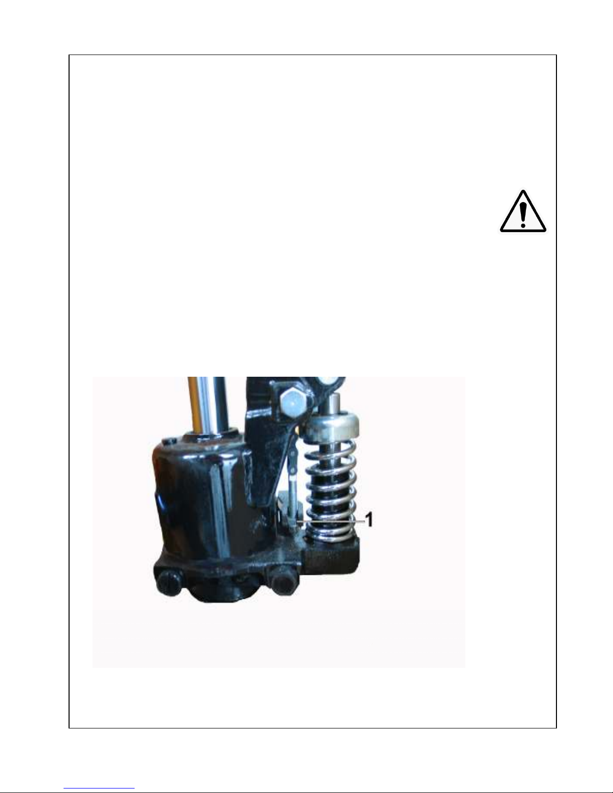
2. Using screw driver to lift up the Cam (17) and put the adjusting nut into the
Cam slot, check the correct position of the chain. (see Pitc 2, 1).
2.5 Remove the Pump locker (Pict 1,Nr.3)
2.6 Now the andle is already assembled to the and Pallet Truck.
Pict 2

5
3 To adjust the release device
On the handle of this hand pallet truck, you can find the lever, which operates in
three positions
:
Lower ................................ = Lowering the fork .......................... LOWER-Position
Drive ................................. = Drive the truck ................................... Drive-Position
Raise ................................ = Lift the fork ........................................ Raise-Position
If however they have been changed, you can adjust according to the following
steps
3.1 If the forks elevate while pumping in the DRIVE position, turn the adjusting
nut (Part No. 59) on the adjusting bolt (Part No. 58) clockwise until pumping
action does not raise the forks and the DRIVE position properly.
3.2 If the forks descend while pumping in the DRIVE position, turn the nut (Part
No. 59) counter-clockwise until the forks do not lower.
3.3 If the forks do not descend when the Lever is in the LOWER position, turn
the nut (Part No. 59) clockwise until raising the Lever (Part No. 51
) lowers the
forks. Then check the DRIVE position according to item 3.1 and 3.2 to be
sure that the nut (Part No. 59) is in the proper position
.
3. If the forks do not elevate while pumping in RAISE position, turn the nut (Part
No. 59) counter-clockwise until the forks elevate while pumping in the RAISE
position. Then check the LOWER and DRIVE positions according to item 3.1,
3.2 and 3.3 .

6
.0 Handling
.1 Driving and Steering the truck with Handle
The handle is adjusted directly to the steering wheels. The steering wheels will
follow the position of the handle.
Pict 3

7
.2 How to take the load
Drive the truck slowly in front of the pallet. Then, drive the fork of the truck under
the pallet up to end of the fork length. (Pict 3.A).
Lift the load by pumping the handle at Raise position.The load must be on the
center of the hand pallet truck. Otherwise, the hand pallet truck can be overturned
.3 Drive with load
It is not necessary to pump the pallet truck to the highest position to drive. You
must pay attention to the space between the bottom of the pallet and always keep
the pallet clear of the floor. You should carefully drive the hand pallet truck at a
stable speed paying due care and attention to the environment around you.
. Lowering the Load
Lift the Lever to the Lower position, ensuring a free space behind. Then the truck
can be pulled out of the pallet.
.5 How to use the hand pallet truck on the truck
Only move the pallet truck slowly, at all times be careful that the hand pallet truck
can not fall down from the truck or the user will not be in the middle between the
hand pallet truck and other loads. If the pallet truck is not used, it must be firmly
fixed on the truck when the truck is moving.
5.0
Service and warranty
5.1 Oil
The ydraulic oil in the pallet truck is used for work condition of 6°C to 45°C only.
If the pallet truck is used in a temperature under 6°C , it must be used with other
ydraulic oil with vicostity under 10.
Please check the oil lever every six months. The hydraulic oil volume in the pump
is 300 ml.
Used oil must be disposed off according to the latest regulations.
5.2 To remove the air
The air may come into the hydraulic oil because of transportation or pump in upset
position. It can cause that the forks do not elevate while pumping the RAISE
position. The air can be removed in the following way: Let the Lever (Part No. 51)
on the LOWER position, then move the andle up and down several times.
5.3 Daily check and Maintenance
Daily check of the pallet truck can limit wear as much as possible. Special attention
should be paid to the wheels, the axles, as thread, rags, etc. It may block the
wheels. The forks should be unloaded and lowered in the lowest position when the
job is over.

8
5. Lubrication
All bearings and shafts are provided with long-life grease at the factory. You only
need provide long-life grease at monthly intervals or after each time the truck is
cleaned thoroughly to the lubrication points.
6.0
Guide to safety operation
6.1
Operator should read all warning signs and instruction here and on the pallet
truck before using this truck
6.2 Do not operate a hand pallet truck unless you are familiar with it and have
been trained or authorized to do so.
6.3 Do not operate a hand pallet truck unless you have checked its condition. Give
special attention to the wheels (part No. 26, Part No. 71), the andle unit, the
fork unit, the cam (Part No. 17), etc.
6. Do not use the pallet truck on a uneven or slopping ground. Do not use the
pallet truck on gradients.
6.5 The pallet truck is not allowed to be used in insufficiently illuminated areas.
Minimum illimination must be at least 50 lux.
6.6 If the pallet truck is moving, it is not allowed to turn the handle into the right
angle to stop the pallet truck.
6.7 It is forbidden to use hand pallet truck for people transportation.
6.8 It is not allowed to use the pallet truck as a jack.
6.9 It is not allowed to use the fork of the pallet truck as a lever to lift loads.
6.10 Do not load like the picture 3.B.
6.11 Do not load over maximum capacity.
6.12 It is not allowed to use the pallet truck in risky conditions.
6.13 It is not allowed to use the pallet truck in direct contact with food.
6.1 It is not allowed to use the pallet truck in explosive atmosphere.
6.15 Operator must wear safety boots and gloves.

9
6.16 Whilst the goods are being transported all none operational staff should be at
a minimum
distance of 600mm.
6.17 At service work, it is not allowed to scatter parts.
6.18 Under any special conditions or environments, the operator should carry out
all relevant risk assessments and method statements before commencing work
with the pallet truck
.
6.19 It is forbidden to use the pallet truck if there is a risk that the pallet truck and
load may fall down, for example, from unsecured ramps.
7.0
Guarantee
This hand pallet truck is guaranteed within 12 months from the date of
purchase. The guarantee is only given if the hand pallet truck is used and serviced
as instructed in this Manual. There is no guarantee for consumable parts or
damage caused by misuse.

10
8.0
TROUBLE SHOOTING
No.
Trouble Clause Fixing Methods
1 The forks cannot be up at
the max height
The hydraulic oil is not enough Pour in the oil
2
The fork cannot be lifted
up
- Without hydraulic oil
- The oil has impurities
- The nut (Part No. 59) is too high, keep the
pumping valve open.
- The air comes into the hydraulic oil.
- Fill in the oil
- Change the oil
- Adjust the nut (Part No.59) (see
item 3.4)
- Bannish the air (see item 5.2)
3
The forks cannot be
descended
-The piston rod (Part No. 9) or pump body
(Part No. 15) is deformed resulting from
partial loading slanting to one side or over
loading.
- The fork was kept in the high position for
long time with piston rod bared to arise in
rusting and jamming of the rod.
- Adjusting the nut (Part No. 59) is not the
correct position.
- Replace the piston rod (Part No. 9)
or the pump body (Part No. 15)
- Keep the fork in the lowest position
if not using, and pay more attention
to lubricate the rod.
- Adjust the nut (Part No.59) (see the
item 3.3)
4
Leaks
- Sealing parts worn or damaged.
- Some parts creaks or worn into small
- Replace with the new one.
- Replace with the new one.
5
The fork descends
without the release valve
worked.
- The impurities in the oil cause the release
valve to be unable to close tight.
- Some parts of the hydraulic system is
cracked or bored.
- The air comes into the hydraulic oil.
- Sealing parts worn or damaged.
- The adjusting nut (Part No.59) is not the
the correct position.
- Replace with the new oil.
- Inspect and replace the waste
parts.
- Bannish the air (See item 5.2)
- Replace with the new one.
- Adjust the nut (Part No.59) (see the
item 3.3)
Note: Do not attempt to repair the pallet truck unless you are trained or authorized to do so.
8.1 Inspection
The hand pallet truck must be inspected by authorized person minimum one time per year.
The result of checking must be filled in the report.
VBG 36, § 37
8.2 Disposal
After using, the pallet truck should be disposed corresponding to the law regulations.
All parts should be brought for recycling.

11
Assembling break into Hand Pallet truck
1. Unscrew the screw pin of the
break
2. Use a hammer and pin driver to
remove spring pin at the steering
wheel (part No. 23)
3. Remove the wheels (Part No. 26)
and the steering wheel axis (Part
No. 21)out of the hand pallet truck
4. Lift the whole hand pallet truck up
and assemble the break into the
pump body (Part No. 15)
5. Let the steering wheel axis (Part
No.21) go through the hole of the
pump body (Part No. 15) and the
hole of the break
6. Screw in the screw pin of the
break to make sure that the beak
and the steering wheel axis (Part
No. 21) are totally connected to
the pump axis.
7. Assemble the two steering wheels
(Part No. 26) back into the wheel
shaft
8. Use hammer to place the spring
pin (Part No. 23) into the holes.
9. Screw in or out the screw pin to
have a good distance between the
wheels and the break.
10. Press “LOCK” to break a hand
pallet truck. Press “MOVE” before
using or moving hand pallet truck

Part No Description Quant. Part No Description Quant.
1 Plunger Piston 1 43 Ball housing 1
2
Dust Seal Ø18 - Ø26 - 4/6
1 44 Steel Ball Ø5 1
3 O-ring Ø17.8 x 2.4 1 45 andle BTN - 2500 1
4 Back-up ring Ø18 x Ø22 x 1.25 1 46 anle Axis 1
5 E-ring Ø20 1 47 Spring Pin Ø3 x 25 1
6 Spring Cap 1 48 Roller Pin 1
7 Spring 1 49 Roller 1
8 Steel Ball Ø14 1 50 Bushing 2
9 Ram Piston 1 51 Lever 1
10
Dust Seal Ø32 - Ø40 - 5/6.5
1 52 Plastic Roller 1
11 O-ring Ø30.8 x 3.6 2 53 Spring Plate 1
12 Back-up ring Ø32 x Ø38 x 1.5 1 54 Spring Pin Ø4 x 16 1
13 Oil Plug 1 55 Spring Pin Ø4 x 16 1
14 O-ring Ø6 x 1.8 1 56 Spring Pin Ø4 x 30 2
15 Pump Body BM - N32 1 57 Spring Pin Ø6 x 30 1
16 Spring Pin Ø8 x 25 1 58 Anchor Bolt 1
17 Cam 1 59 Nut M6 1
18 Bearing Base 1 60 Chain 1
19 Bearing 51109 1 61 Release Rod 1
20 Table 1 62 Fork 1
21 Steering Wheel Axis 1 63 Lifting Yoke 1
22 Spring Pin Ø6 x 35 2 64 Plastic Bushing 36 x 25 x 30 2
23 Spring Pin Ø5 x 30 10 65 Table Pin 2
24 Spring Pin Ø6 x 45 1 66 E-ring Ø20 2
25 Snap Ring Ø45 1 67 Lifting Yoke Axis 540 1
26 Steering Wheel Ø180 x 50 2 68 Rod 1150 2
27
Bearing 6204
12
69
Arm
2
Part List
XTN 540 - 1150
27
Bearing 6204
12
69
Arm
2
28 Washer Ø20 x Ø40 x 3 2 70 Steel Plate 4
29 Release Nozzle 1 71 Load Wheel 4
30 O-ring Ø4 x 2 2 72 Load Wheel Axis 4
31 Spring 1 73 Arm Pin 2
32 Release Plug 1 74 Rod Pin 2
33
Copper Washer Ø14.5 x Ø22 x 1.5
1 75 Washer 4
34 Spring 1 76 Spring Pin Ø5 x 40 2
35 Spring 1 77 Grease Nipple 1
36 Steel Ball Ø6 2 78 Rubber 1
37 Valve ousing 1 79 Screw M6 x 10 1
38 Steel Ball Ø9 1 80 Bushing 22 x 20 x 14 x 1 2
39 Relief Screw 1 81 Bushing 18 x 16 x 16 2
40 O-ring Ø11.2 x 2.65 1 82 Bushing 22 x 20 x 20 10
41 Relief Screw 1 83 inner Circlip Ø25 2
42 Spring 1
12

13
Table of contents
Other LoadSurfer Lifting System manuals

Popular Lifting System manuals by other brands


Da-Lite
Da-Lite Da-Lift Series Instruction book

morse
morse 400A-96-114 Operator's manual

CHICAGO
CHICAGO 90582 Assembly and operating instructions

Poweramp
Poweramp CentraAir Owner & user manual

stellar labs
stellar labs 108-11-32 owner's manual

R. Beck Maschinenbau
R. Beck Maschinenbau HS 300 MIDI operating manual