manuals.online logo
Brands
  1. Home
  2. •
  3. Brands
  4. •
  5. Sabaj
  6. •
  7. Lifting System
  8. •
  9. Sabaj Premium K Series User manual

Sabaj Premium K Series User manual

www.rtv.sabaj.pl
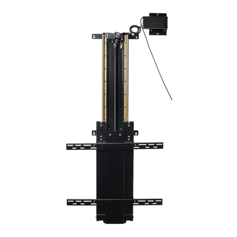
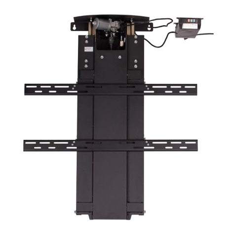
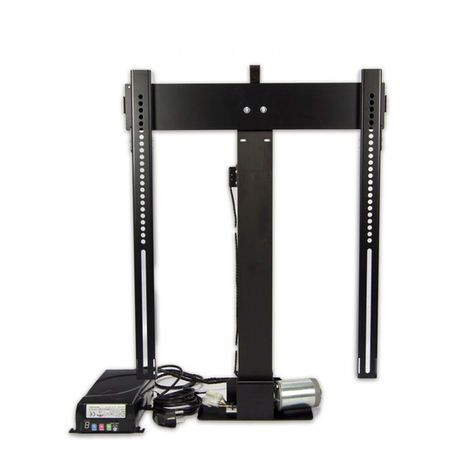
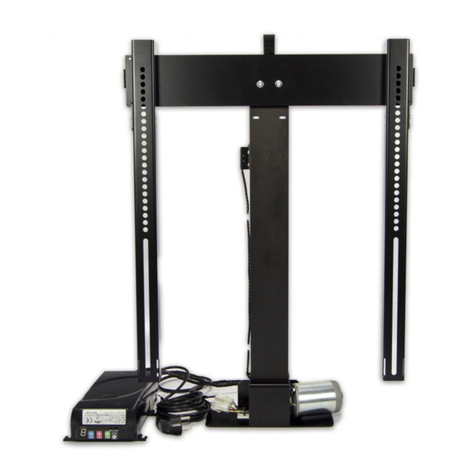
K-SERIES TV LIFT
PREMIUM
User Manual
www.rtv.sabaj.pl
2
List of contents
Lp
Part description
Quantity
1
Lift Column
1 pc
2
Horizontalbeam
1 pc
3
Vertical beam
2 pcs
4
Beam stiffener
1 pc
5
Supporting beam pt1
1 pc
6
Supporting beam pt2
1 pc
7
Adjustment bracket for supporting
beam
2pcs
8
Mounting bracket
1 pc
9
Chain brackets
1 set
10
Cable chain
1 pc
11
Control box + RF remote
1 set
12
Screws
1 set
13
Nuts
1 set
4xM8 +
4xM6
14
Manual
1 pc
15
Allen Key “4”
1 pc.
16
M6/M8 Wrench
1 pc.
www.rtv.sabaj.pl
3
Required tools: Cross-Headed Screwdriver
------------------------------------------------------------------
1. The supporting beam needs to be assembled as on Pic.1.
Use the supplied wrench to tighten the nuts.
M8 nut
4x
M6 nut
4x
Pic.1
2. Use the bracket to connect supporting beam to with the lift, as you see onPic.2.
Pic. 2
M6 nut
x2
www.rtv.sabaj.pl
4
3. Set the adjustment brackets so that each one of them faces the side of the cabinet, as shown on Pic.3. Attach
the adjustment brackets with woodscrews, so they are mounted firmly on the furniture. Note: Always check if
the woodscrews aren’t too long for your furniture! Also attach base of the lift to the bottom of your furniture
with woodscrews.
Pic.3
4. Mount horizontal beam to the column, using attached screws (Pic.4).
Pic.4
Woodscrew 4x16
10x
Woodscrew 4x16
3x
110mm
With the supporting beam the furniture back Wall is not required. You will only
need to put a plank with hinges for the top lid as shown on the Picture A.
Pic. A
www.rtv.sabaj.pl
5
5. Hang control box on the hangers, as you see on Pic.5, then connect Control box to the lift as onPic.6.
You can eventually place the control box elsewhere, as long as the cables are long enough and it
doesn’t get in the way of the TV nor the Lift.
Note: remember that the control box should hang, do not use excessive force to tighten the screws
on the control box.
Pic.5
Pic.6
www.rtv.sabaj.pl
6
6. Mount cable brackets and cable chain as you see on Pic.7.
Pic.7
7. Using screws provided by your TV manufacturer mount the vertical beams to your screen. The beams should
be about 45mm inch below upper edge of the screen. Connect vertical brackets by a stiffener as shown on
Pic8.
Pic.8
Upper Cable chain
M8 Nut
2x
M6 Nut
2x
www.rtv.sabaj.pl
7
8. Loosen the lower brackets on the vertical beams, as shown onPic.9
Pic.9
9. Hang the screen with vertical beams mounted on the horizontal beam on your Lift.(Pic10)
Pic.10
www.rtv.sabaj.pl
8
10. Move the lower brackets on the vertical beam up and tighten the screws(Pic.11)
11. Connect lower cable bracket to the cable and then to the beam stiffener. You can lead all of the cables
from your TV through the cable chain.
Lower
cablebracket
Pic.1
2
www.rtv.sabaj.pl
9
12. Now go to the Control box setup.
www.rtv.sabaj.pl
10
CONTROL BOX MANUAL
K-Premium RF
V 4.0.9
Control Unit’s keypad.
Note: depending on your lift version the socket type will be compatible
With your country standards.
Programming the VP (Viewing Position)
The new K-Premium Control Box allows you to setup both top and down viewing position. Although it is recommended to drive
the lift to the lowest position before programming the Viewing Position (VP) , you can enter the setup from any position you
like.
A)To setup the DOWN VP do the following :
- drive the lift to your desired down position with the up/down buttons (lowest is recommended)
- Press & hold the setup button for at least 3 seconds. You will hear a short “beep”
- The Red setup Led is now lit
B) To setup the UP VP :
-(the setup led is still lit)
- Drive the lift to the desired UP position with UP/DOWN buttons
-Press & hold the setup button for at least 3 seconds. You will hear a short “beep”
- the green VP led should now be off
RJ45 socket
Control Box Rear
Lift to control
box socket
Control Box Front
Lift Power Plug compliant
with your country standards
TV Power Guard socket
www.rtv.sabaj.pl
11
Control Box Status
The height from which
you enter the VP mode is
your preffered low
position
„BEEP”
You have entered the VP
mode. The lift will not go
lower than this positin
after you leave VP
Set up the Up VP position
with UP/DOWN buttons
„BEEP”
Press&hold Setup to
leave the setup mode.
Your lift range is now set.
Set
DOWN
VP
Down VP
acknowledged
Max UP
VP
Max
DOWN VP
Adjusted
movement
EXAMPLE:
Set UP VP
www.rtv.sabaj.pl
12
RF Remote Control assignment
The supplied RF remote is already programmed with your TV-Lift . In case you want to program a new one , follow these steps :
-Press& hold the RC Set button for about 3 seconds
-The lift will wait for any signal from a remote for 15 seconds from now on
-Press any button on your remote
-The lift will acknowledge the new remote , which will now be operative
Note : The Control Box has a memory of 8 Remotes. If you will want to program the 9th remote control –the 1st will be
deleted
POWER GUARD (Standby mode detection)
If you will plug your TV in to The control box socket –it will monitor the energy consumption of your screen. If the user
attempts to hide the fully operating screen (turned ON), the control box cuts the power out. After lifting the screen back to the
viewing position, the power will be restored to it. If the TV is turned off or in standby mode, the power will not be cut out.
Safety system operation
The intelligent safety system detects the obstacles when the screen is moving down as a weight difference. It does not require
any calibration, which is done automatically. After detecting an obstacle the lift stops, and moves up about 5 centimeters. The
safety system works only during the down movement. When the safety system is activated, the blinking “1” appears on the
display.
Active RJ-45 Socket
Your Premium Control box is equipped with the active RJ-45 Socket , which allows to plug additional accessories
supplied by SABAJGROUP. NOTE: Only the original SABAJGORUP accessories will work with your Premium Control
Box. If you attempt to modify or connect any other devices via the RJ-45 Port, you might damage the Control Box and
you will loose the warranty for doing so.
Display messages:
The numeric display shows the information about the lift operation. If the display shows :

“0” Blinking -electric motor overload (currentexceeded)

“1” Blinking – safety system has been triggered

“2” Blinking – power cut out when hiding the activescreen

“3” Blinking -wiring loom not connected to the control box

“4” Blinking - lower limit switch activated

“5” Blinking – upper limit switch activated Pressing any
button will delete the displaymessage.
www.rtv.sabaj.pl
13

Other Sabaj Lifting System manuals

Sabaj M Series User instructions

Sabaj

Sabaj M Series User instructions

Sabaj WP-560 User instructions

Sabaj

Sabaj WP-560 User instructions

Sabaj K-DOWN User instructions

Sabaj

Sabaj K-DOWN User instructions

Sabaj K-1 Rotolift+AutoLid User instructions

Sabaj

Sabaj K-1 Rotolift+AutoLid User instructions

Sabaj MOBILIFT ECO 650 User instructions

Sabaj

Sabaj MOBILIFT ECO 650 User instructions

Sabaj K-2 User manual

Sabaj

Sabaj K-2 User manual

Sabaj K-1 Rotolift User instructions

Sabaj

Sabaj K-1 Rotolift User instructions

Sabaj K Series User manual

Sabaj

Sabaj K Series User manual

Popular Lifting System manuals by other brands

Challenger Lifts 4018XFX Installation, operation & maintenance manual

Challenger Lifts

Challenger Lifts 4018XFX Installation, operation & maintenance manual

twin busch TW M-04 Installation, operation and maintenance manual

twin busch

twin busch TW M-04 Installation, operation and maintenance manual

MAHLE CAL-10 Operation manual

MAHLE

MAHLE CAL-10 Operation manual

JLG LiftPod FT70 Operation, Safety, Service and Maintenance Manual

JLG

JLG LiftPod FT70 Operation, Safety, Service and Maintenance Manual

SATA AE5105 user manual

SATA

SATA AE5105 user manual

TEUPEN LEO 21GT manual

TEUPEN

TEUPEN LEO 21GT manual

Reid PORTA-GANTRY 500 Assembly & operation

Reid

Reid PORTA-GANTRY 500 Assembly & operation

Lippert Components ground control 3.0 user manual

Lippert Components

Lippert Components ground control 3.0 user manual

Aquatic Access IGMT installation guide

Aquatic Access

Aquatic Access IGMT installation guide

Sulzer ABS 5 kN Installation and operating instructions

Sulzer

Sulzer ABS 5 kN Installation and operating instructions

Ravaglioli KPH 370.50 K Translation of the original instructions

Ravaglioli

Ravaglioli KPH 370.50 K Translation of the original instructions

Hallins Reflex 200 instruction manual

Hallins

Hallins Reflex 200 instruction manual

Haklift NOSP250 Original instructions

Haklift

Haklift NOSP250 Original instructions

haacon 2724.10 operating manual

haacon

haacon 2724.10 operating manual

Clarke STRONG-ARM CCL2250 Operation & maintenance instructions

Clarke

Clarke STRONG-ARM CCL2250 Operation & maintenance instructions

Jungheinrich EME 112 operating instructions

Jungheinrich

Jungheinrich EME 112 operating instructions

Braun Corporation RA300 Operator, Installation, Service Manual

Braun Corporation

Braun Corporation RA300 Operator, Installation, Service Manual

Corghi Erco X5000 CT LT PT2 FAST Operator's manual

Corghi

Corghi Erco X5000 CT LT PT2 FAST Operator's manual

manuals.online logo
manuals.online logoBrands
  • About & Mission
  • Contact us
  • Privacy Policy
  • Terms and Conditions

Copyright 2025 Manuals.Online. All Rights Reserved.