Cascade
When multiple boilers are installed, they can be wired together
in a cascade sequence. A maximum of eight boilers can be
controlled from a single control. In this application one boiler
would be designated as the Leader control and all others would
be designated as Member controls.
If the water temperature at the inlet side of the indirect heat
exchanger sensor is less than the set point + the turn-off offset -
the off-on differential, then the control will initiate a call for heat
on the Cascade (see the FTXL Service Manual for an explanation
of the offset and differential). The Leader will energize the lead
boiler on the Cascade. For a new startup this will be the Leader
boiler.
The boiler will fire at its ignition speed and will then modulate
its firing rate to maintain the set point. If the first boiler reaches
100% of its firing rate, the Leader will calculate at what point the
second boiler could fire at 20% of its firing rate. At this point,
the Leader will fire the second boiler on the Cascade. For a new
startup, this would be the first Member boiler. The boiler will
fire at its ignition speed and will then modulate its firing rate to
maintain the set point.
If the set point still cannot be met, the Leader will continue
firing more Members until either the heat demand is met or all
boilers on the Cascade are firing. As the heat demand decreases,
the last boiler on will modulate down to 20% of its firing rate.
Once the demand for that boiler is zero, it will shut down. As
the heat demand decreases further, the second to last boiler will
modulate down and shut off. This will continue until the demand
is satisfied and all boilers are shut off.
Wiring of the Cascade
When wiring the boilers for Cascade operation, select one boiler
as the Leader boiler. The remaining boilers will be designated
as Members. See “Configuration of the Cascade” for a detailed
explanation of this procedure.
Communication between the Leader boiler and the Member
boilers is accomplished by using shielded, 2-wire twisted pair
communication cable. Connect one of the twisted pair wires
to terminal A on each of the Low Voltage Connection boards
(FIG. 3), and the other wire of the twisted pair to terminal B on
each of the Low Voltage Connection Boards. Connect the shield
wires to one of the shield ground terminals on the Low Voltage
Connection Boards. If more than two boilers are on the Cascade,
daisy chain the wiring from the Sequencing terminals on the
second boiler to the Sequencing terminals on the third boiler, then
from the third to the forth, and so on. The connections between
boilers can be made in any order, regardless of the addresses of
the boilers. Try to keep each cable as short as possible.
Configuration of the Cascade
Please note that the brackets ([]) denote screen
status.
NOTICE
When installed in a Cascade system, the individual controls must
be programmed for cascade operation. This is accomplished by
accessing the control parameters.
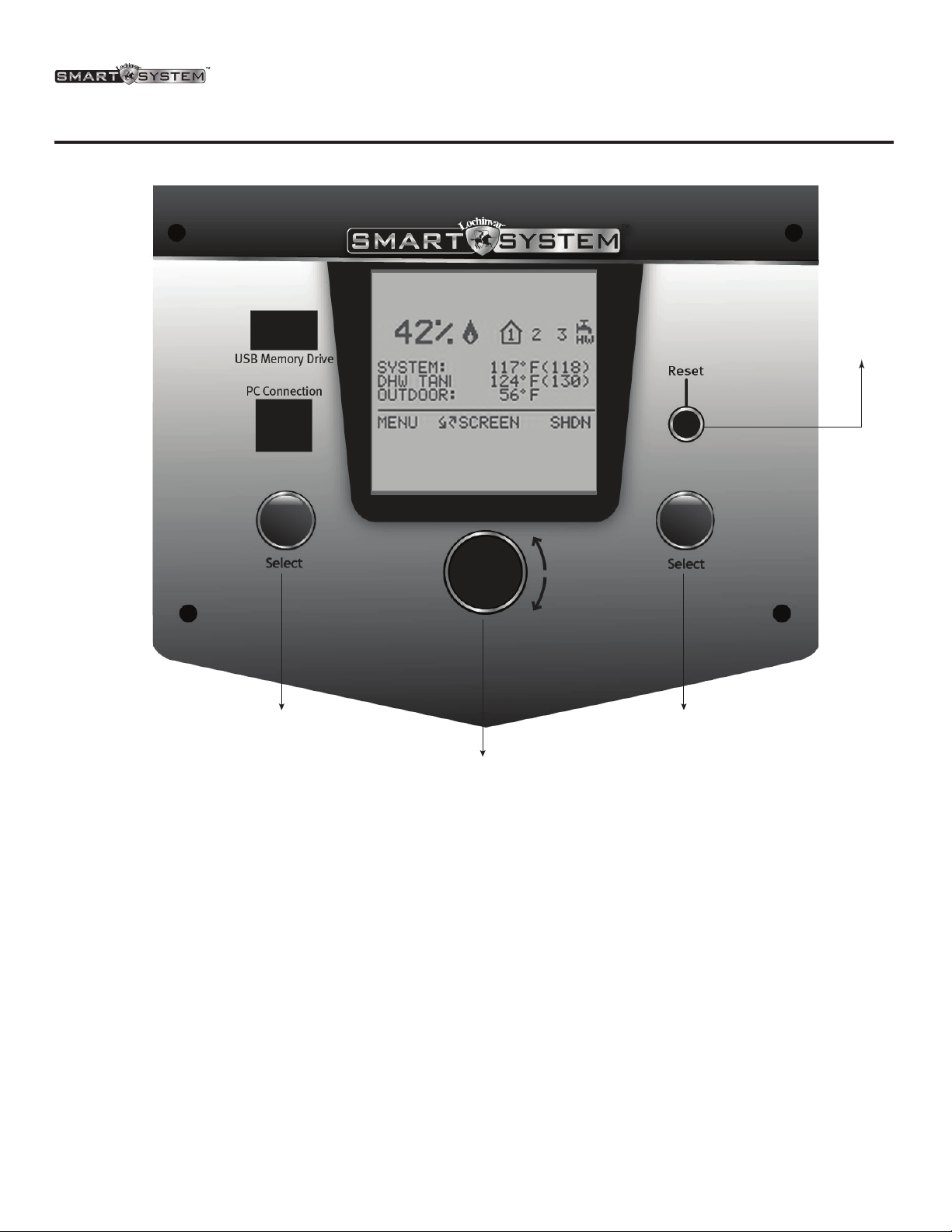
Press the [MENU] key for at least five (5) seconds. Input the
Installer code as described in the FTXL Service Manual. Once the
control parameters have been accessed, use the NAVIGATION
DIAL to select the Control Mode parameters. Press the
NAVIGATION DIAL to access these parameters.
Rotate the NAVIGATION dial to select the parameter “Cascade
Address”. Press the NAVIGATION dial to access this parameter.
Each appliance in the Cascade system must be programmed
with its own address. The boiler designated as the Leader will
have an address of 0. The remaining boilers in the Cascade
will be Members and have addresses from 1 - 7. Rotate the
NAVIGATION dial to select the appropriate address. Press the
RIGHT SELECT SAVE key. If installing the boilers in an
existing system, the new boilers should be programmed as the
Leader and/or the higher number addresses.
Press the RIGHT SELECT HOME key to upload the address
into the control. Repeat this procedure for all boilers in the
Cascade, designating the Leader control and the Member controls.
100326095_2000582397_Rev A 9 of 16