Locinox VINCI - LMKQ V2 User manual

USER GUIDE ENGLISH
VINCI - LMKQ V2
LEONARDO - LLKQ V2
&


• As manufacturer of this product, we guarantee that we have
taken all the necessary steps in order for this product to comply
with the current safety requirements.
Copyright
Copyright © 2009 Locinox. All rights reserved.
This product incorporates copyright protected technology that is protected by a number of EU
patent method claims and other intellectual property rights owned by the Locinox Corporation
and other rightholders.
Use of this copyright protected technology must be authorized by the Locinox Corporation.
Reverse engineering or disassembly is prohibited. No part of this publication can either
be reproduced, communicated, transcribed, stored in a retrieval system or be translated
into any language in any form or by any means, whether electronic, mechanical, magnetic,
optical, chemical, manual or otherwise, unless explicit written consent has been given by the
copyright holder.
Notice
The contents of this publication is subject to change. The company reserves the right to alter the
contents of this publication at any time and without notice. The contents of this publication may
contain inaccuracies or typographical errors and is supplied forinformational use only.
Technical Support
If you require any additional information or assistance during the installation, please contact your
dealer, who will be able to provide the latest information. Alternatively, you can visit the Locinox

4
Manual - English
1. Introduction
Thank you for choosing a Locinox mechanical code lock! Please read the following instructions
thoroughly before mounting the Vinci or Leonardo. Enclosed you will find all relevant user infor-
mation concering the Vinci and Leonardo.
2. Package contents
Please check if your package contains the following items:
Please contact your supplier should any of the above items be damaged or missing.
Vinci
Leonardo
1
2
3
2
3
4
1

5
Mechanical code lock
for swinging gates
Vinci Leonardo
2
1Mechanical code lock
for sliding gates
3006Club Aluminium handle pair
& hexkey (3mm)
3
Twistfinger-set
3006Club Aluminium handle pair
& hexkey (3mm)
Cylinder keys (3x) & Code screws (4x)
& Cover caps (2x)
4Cylinder keys (3x) & Code screws (4x)
& Cover caps (2x)
/
3. Components
The drawing below shows the names of the most important components. This drawing can be used
as reference throughout the manual.
A
B
A
B
C
D
HE
F
G
I
C
D
HE
F
G
I
J
K
J
K
L
M
N
A
B
C
D
E
F
G Distance tube
Cylinder rain and dust cover
Key
Handle
Reset button
Code panel
Rain and dust cover H
I
J
K
L
M
N Twist finger
Night bolt (N)
Self-latching bolt (D)
Closing cover
Cover screw
Cylinder screw
Hexagon socket head screw
Vinci Leonardo

6
4. Specifications
• The Vinci & Leonardo are 100% mechanical code locks, which does not need a battery nor
electricity to function.
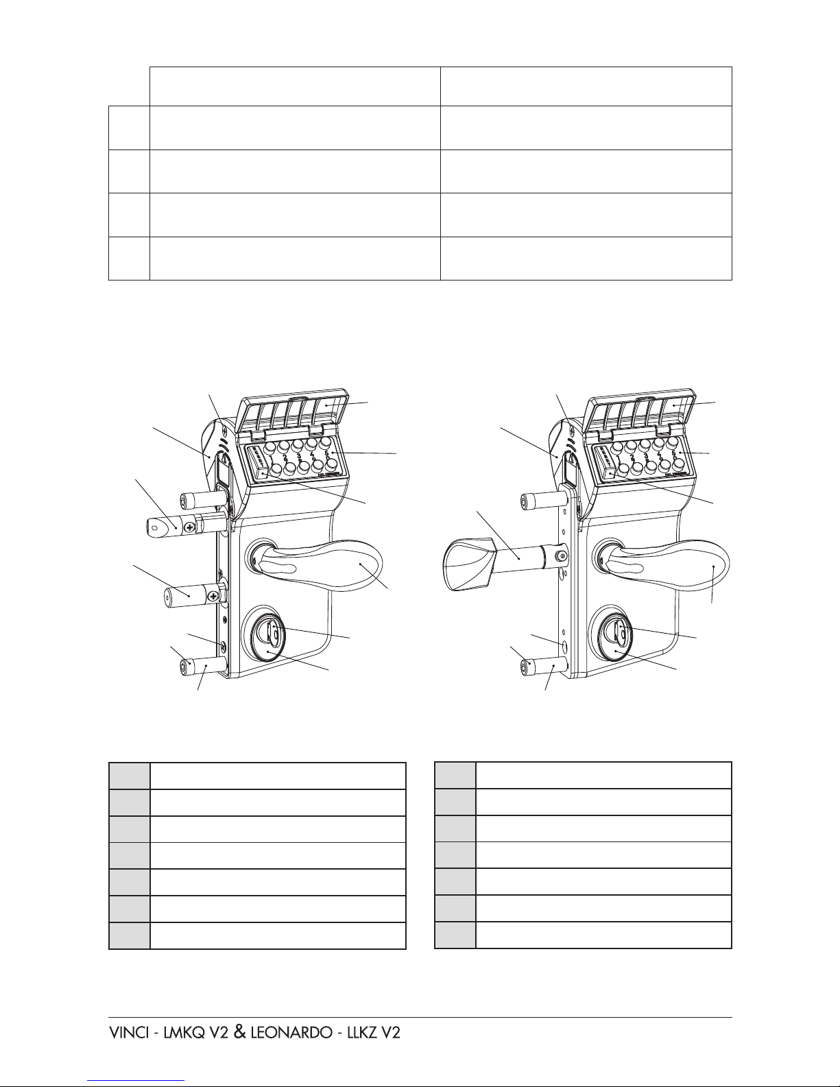
• The code lock is equipped with a double-sided operational code panel. This enables you to
work with different entrance and exit codes.
• The handle is blocked by means of the code panel. Upon entering the correct code, the handle
is released and you can retract the self-latching bolt by means of the handle.
• Both code panels are protected by an aluminium cover. This prevents dust and rain from
penetrating.
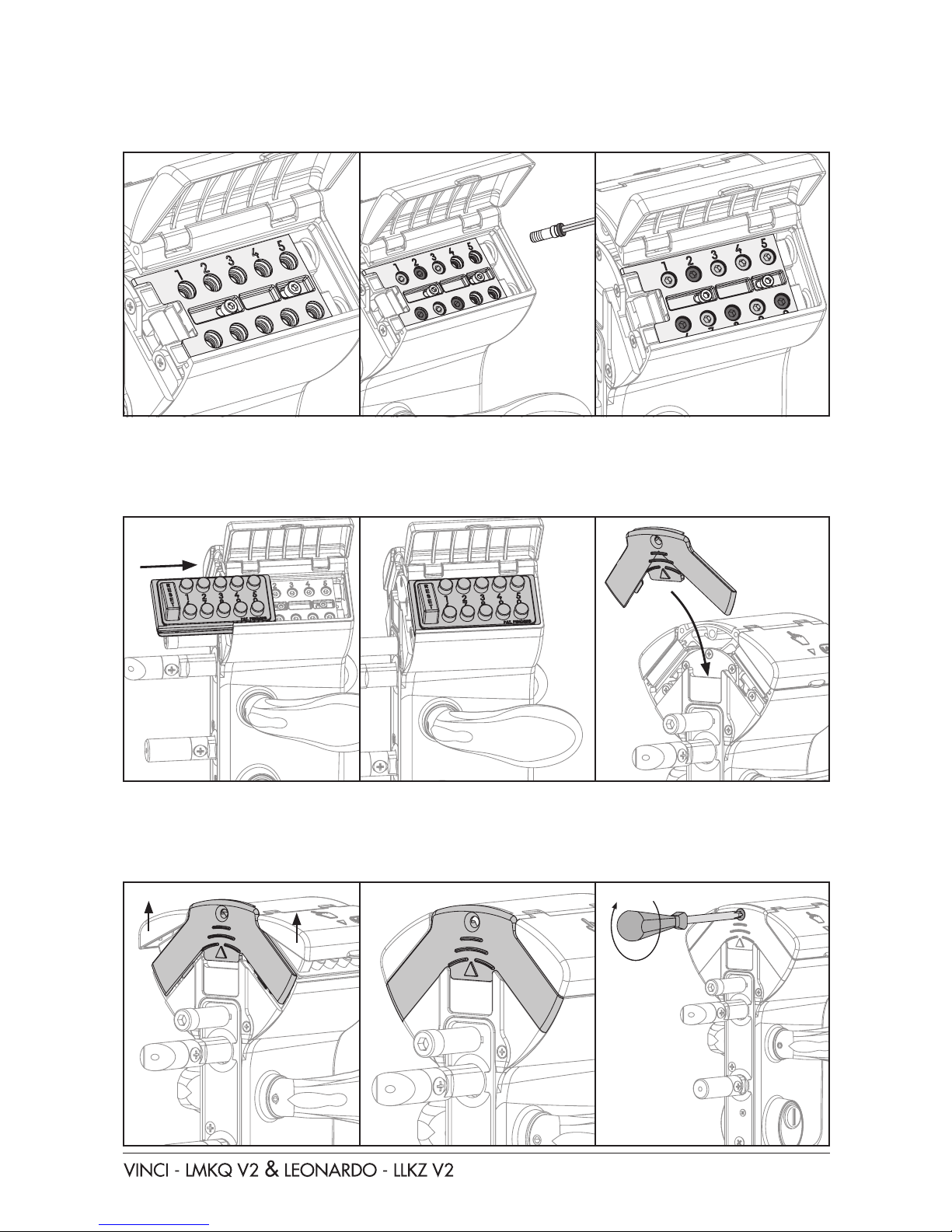
• The high-value code lock was also designed in a very user-friendly manner.
Changing the code setting is very easy. A 4 to 6-digit code can be set by means of the
additional code screws.
• The locks are equipped with a security press plate which rules out detection of the secret code
by putting pressure on the handle. After the correct code has been entered and the gate has
been opened with the handle, the code is automatically reset.
180°
20 mm
20 mm
A
15 mm
20 mm
(D)
(N) • As each mechanical code lock is equipped with a
key-operation, the self-latching bolt can be opened by
manipulating the key without entering the code. The
self-latching bolt can be retracted 15 mm with the key.
The throw of the night bolt is 25 mm.
VINCI only
• If the night bolt is in a locked position, the lock remains locked irrespective of
the code input.
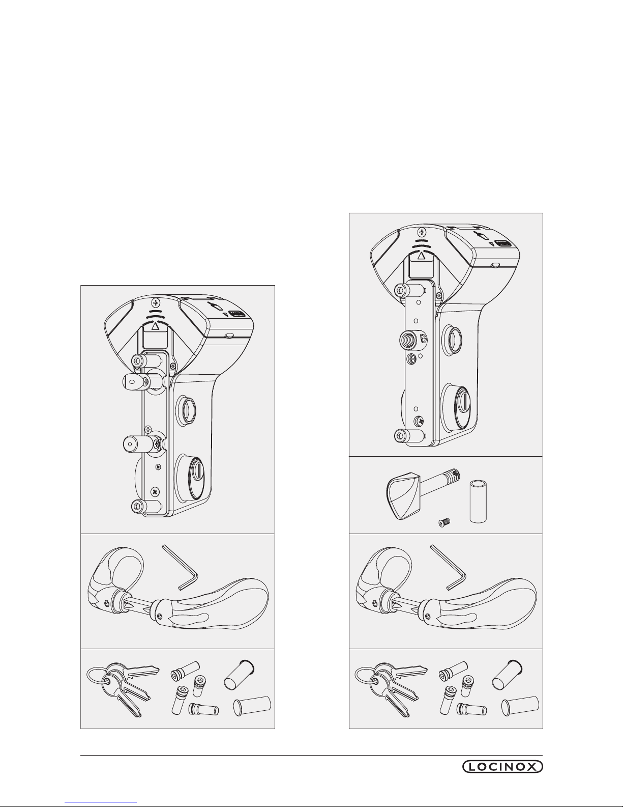
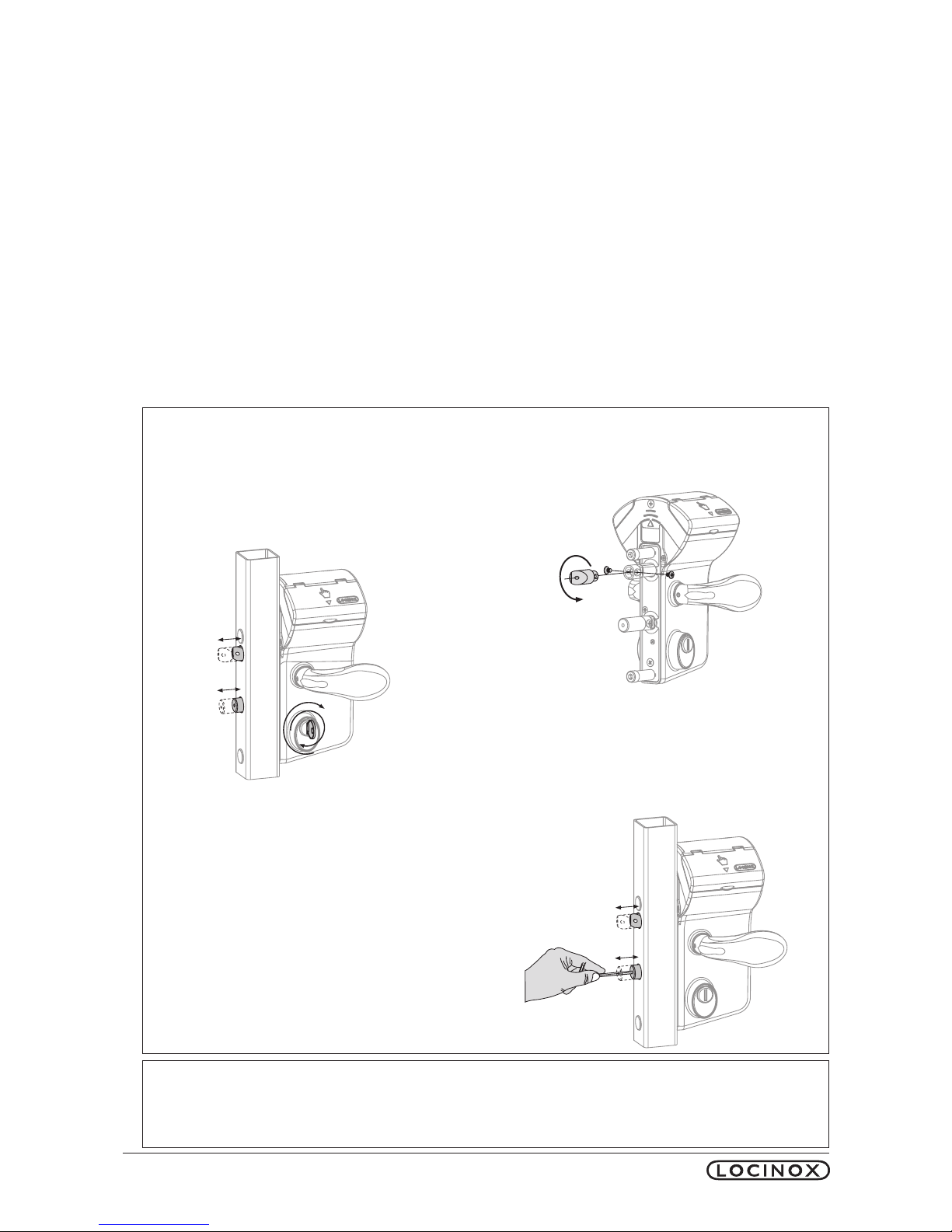
• The self-latching bolt can easily be
adapted for left- or right turning gates.
• Both the night bolt as well as the
self-latching bolt can be adjusted
20 mm continuosly, which enables
you to set the correct dept of each
bolt into the keep in any situation.
LEONARDO only
• Stainless steel shell around the twistfinger prevents cut-through of the pen.

7
5. Profile preparation
Determine the correct position of the lock in the gate frame. The mounting holes can be prepared
by means of the below drawings.
BEWARE! For the Vinci, the holes of the self-latching bolt and the night-bolt, need to be larger
(Ø24) at the back of the gate frame than those at the front (Ø18). This enables
you to turn the Vinci into the gate frame quite easily in case of a minimum
distance (110 mm) between the gate frame and the first gate bar.
6. Code setting
Because of safety reasons, the Vinci & Leonardo where developed in such a manner that the code
can only be changed when it is not mounted onto the gate. The default setting of the code is 1-2-3-4.
The steps below explain how you can modify your own personal code in a fast and simple manner.
The Vinci enables the setting of a 4 to 6-digit code.
Ø 9
Ø 24
Ø 24
Ø 9
Ø 15
Ø 15
Ø 18
206060
Vinci
Leonardo
Ø 9
Ø 20
Ø 9
Ø 15
Ø 15
Ø 20
4892

8
Step 1: Remove the closing cover.
First remove the cover screw and then slide out the closing cover.
Step 2: Slide both code panels out of the lockbox.
After removing the code panels, you will find the red and green code screws. When dealing with
a new lock, the green screws are automatically set in position 1-2-3-4, as shown in drawing F.
Step 3: Remove all code screws
Remove all code screws from the code mechanism with the enclosed hex key as shown in
drawings G, H, I.

9
Step 4: Set your personal code
After having removed the code screws from the code mechanism, you can use the green code
screws to set your personal code.
Step 5: Remounting the code panels
After setting your personal code, you are ready to replace the code panels.
BEWARE! The reset button always need to be in front.
Step 6: Replacing the closing cover.
After fixing the code panels, the closing cover can be replaced. Lifting the cover caps slightly
enables you to slide in the closing covers more easily. The lock is now ready to use. It is advisable
to test the lock (see chapter 7 Operation) before mounting.

10
7. Operation
Enter a false code in order to test the reset function. Drawing A After having entered an incorrect
code, the handle remains blocked. Drawing B Now press the reset button and enter the correct
code. Drawing C. The handle can be moved after entering the correct code. This will retract the
lock’s self-latching bolt. Drawing E. After using the handle, the code is automatically reset. In do-
ing so, the code needs to be entered each time in order to open the Vinci. When the Vinci has
been locked by means of the key, the lock can no longer be opened by means of the code panel.
8. Mounting the Vinci
After testing the operation of your lock, the Vinci can be mounted onto the gate. The fast, easy
and typical Locinox mounting is explained below. First slide the distance tubes over the hexagon
socket head screws and fix the lock onto the gate profile by using the hex key. 1& 2. Tighten
the hexagon socket head screws and cover the holes with the enclosed plastic cover caps. 3
A B C
D E
1 2 3

11
8. Mounting the Leonardo
After testing the operation of your lock, the Leonardo can be mounted onto the sliding gate. The
fast, easy and typical Locinox mounting is explained below. First slide the stainless teel shell over
the twistfinger and screw it into the lock. 1Pull back the Leonardo so u can block the twistfinger
by fixing the screw 2. Tighten the hexagon socket head screws and cover the holes with the
enclosed plastic cover caps. 3& 4
10. Removing the cylinder and the dust cover
In order to remove the cylinder or the dust cover, the lock needs to be dismounted. Please follow the
procedure as described in chapter 8 & 9. Only now, it has to be done in reverse order. Once the lock
has been dismounted, you only have to follow the instructions below to remove the cylinder and
the dust cover. Firstly, you need to remove the screw that holds in the cylinder in place. Image A.
Secondly, put the key into the cylinder and turn it until it is blocked at an angle of 45°. Image B.
You can now put pressure onto the key. When pulling it out in a straight line, you will be removing
the cylinder and the dust cover. Image C.
If you now remove the key from the cylinder, you have 3 separate pieces. Images D & E.
A B C
D E
1 2 3 4

Copyright © 2014 Locinox. All rights reserved.
All specifications and figures are subject to change without notice.
Locinox nv - Mannebeekstraat 21 - B-8790 - Waregem - Belgium
Tel. +32 (0)56 77 27 66 - Fax. +32 (0)56 77 69 26
2017-05-31 - rev 2
* M A N U - 0 0 0 0 0 3*
This manual suits for next models
1
Other Locinox Door Lock manuals