LOCKEY SUMO GL2LINX User manual
SUMO™ GL2LINX Installation Instructions
IMPORTANT: USE THESE INSTRUCTIONS TO INSTALL THE SUMO GL2LINX & GL2 GATE LOCK
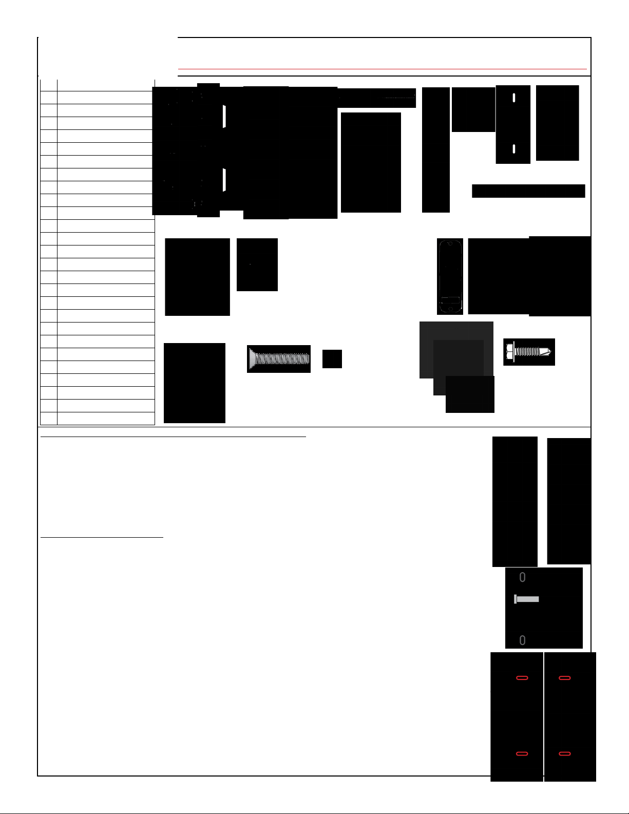
1 Mounting Bracket A
2 Mounting Bracket B
3 Mounting Bracket C
4 Gate Adapter
5 Fence Adapter
6 Security Guide Bolt
7 Keyed Guide Bolt Receiver
8 Latch Assembly
9 Lock Hood
10 Strike Assembly Y
11 Strike Assembly Z
12 Spindle
13 Spacers
14 Strike Plate
15 Support Pin
16 Hex Bolts
17 M4 Screws
18 1/2” Self-Tapping Screws (4)
19 3/4” Large Phillips Screws (2)
20 Rubber Trim Plate
21 Outside Lock Body
22 Inside Lock Body
23 Flat Head M4 Screws
24 Set Screw
25 Jamb Stop
26 M4 Pan Head Screws
27 1” Self-Tapping Screws
INSTALLATION INSTRUCTIONS
1. Hold Gate Adapter (#4) to the 1-5/8” or 1-7/8” gate frame where you would like the lock to mount. Use a marker to
mark holes B, C, and D on both sides of the gate to prepare for drilling (See Diagram 1).
2. Use a 3/8” drill bit to drill holes marked B & D on both sides. Use a ½” drill bit to drill hole marked C on both sides.
3. Align the Gate Adapter with the holes you drilled in the gate. Self-drill two of the 1” Self-Tapping Screws (#27) into the
holes marked E & F on the side of the Gate Adapter (See Diagram 1).
4. Temporarily secure Mounting Bracket A (#1) to the Gate Adapter on the pull side of the gate using a ½” Self-Tapping
Screw (#18) in the center hole of the bracket. The two tabs on Mounting Bracket A must mount on the inside edge of the
gate facing toward the fence post.
a. Insert the Security Guide Bolt (#6) into the bottom hole on Mounting Bracket A with the bolt pointing
towards the fence post. DO NOT tighten the set screw at this time.
5. Secure Mounting Bracket C (#3), Keyed Guide Bolt Receiver (#7) and Strike Assembly Y (#10) to the Fence Adapter (#5).
a. Slide the Keyed Guide Bolt Receiver onto the bottom channel of Mounting Bracket C. The two tabs on Mounting
Bracket C must be on the inside edge of the post facing towards the lock. NOTE: The keyed hook MUST be in
the locked position in order to slide the Keyed Guide Bolt Receiver onto Mounting Bracket C. After the Keyed
Guide Bolt Receiver is installed on Mounting Bracket C, unlock the receiver.
b. Slide Strike Assembly Y onto the top channel of Mounting Bracket C.
c. Secure Mounting Bracket C to the Fence Adapter with the Keyed Guide Bolt Receiver & Strike Assembly Y attached.
i. Use two 2” M4 Pan Head Screws (#26) through the Strike Assembly Y.
ii. Use two 1” M4 Pan Head Screws (#26) through the Keyed Guide Bolt Receiver.
iii. Use two 3/8” M4 Pan Head Screws (#26) through the two tabs on the inside edge of Mounting Bracket C.
6. Hold the Fence Adapter to the pull side of the fence post with everything attached and align the Keyed Guide Bolt
Receiver with the Security Guide Bolt on Mounting Bracket A (See Diagram 2).
7. Once the Security Guide Bolt is aligned and has the ability to slide into the Keyed Guide Bolt Receiver, secure the
Fence Adapter to the fence post with four 1” Self-Tapping Screws in the slotted holes on each side of the adapter (See
Diagram 3).
1 2 3 4 5 6
7
8 9 10 11
12
13 14 20 21
Diagram 2
22
(Single Combination)
22
(Double Combination)
15
16
17
18
19
23 24
A B C
25
IMPORTANT INFORMATION ABOUT YOUR SUMO™ GL2 GATE LOCK
- To retain SUMO™ product warranty, the gate must have a slam prevention device installed. Use of spring closers
and/or self-closing hinges without a slam prevention device will void the warranty. LockeyUSA recommends a
hydraulic gate closer, such as a TB Series gate closer.
- To retain SUMO™ product warranty, the provided jamb stop must also be installed.
- SUMO™ mounts on left and right hand gates. SUMO™ Mounting Bracket A must be mounted on the pull side of
the gate. Lockout feature works on pull side of gate only. If your gate is an inswing gate, you may want to switch
hinges to allow the pull side of the gate to be the exterior or you can simply switch the outside and inside lock
bodies when installing.
- There will be parts included that you will not use for the installation of the SUMO™ GL2LINX and SUMO™ GL2.
26
Diagram 1
A
B
C
D
E
F
Diagram 3
27
Y Z
Gate
Adapter
Fence
Adapter

8. Next, adjust the Security Guide Bolt for added security.
a. With the gate closed, adjust the Security Guide Bolt in or out so the end of the bolt just starts to hit the
v-groove of the Keyed Guide Bolt Receiver.
b. Once the Security Guide Bolt is aligned, remove Mounting Bracket A. Using the provided allen wrench,
insert set screw (#24) into hole on the back side of Mounting Bracket A. Tighten to secure Security Guide
Bolt in place. Make sure the at side of the Security Guide Bolt thread is in contact with the set screw.
9. Secure Mounting Bracket A and Mounting Bracket B (#2) to the Gate Adapter.
a. Place Mounting Bracket A onto the Gate Adapter & secure with three ½” Self-Tapping Screws (2 screws
through the tabs on the inside edge of the Gate Adapter, 1 through center hole used in previous step).
Close the gate and make sure the Security Guide Bolt and v-groove of the Keyed Guide Bolt Receiver
remain aligned.
b. Secure Mounting Bracket B to gate with one ½” Self-Tapping Screw through center hole.
c. Ensure the notch on the bottom tab of Mounting Bracket B aligns with the notch on the bottom tab of
Mounting Bracket A (See Diagram 4). If it does not, you will need to adjust your alignment.
10. Once Mounting Bracket A & B are both secured, place Latch Assembly (#8) onto Mounting Bracket A, slide
the Lock Hood (#9) over top and secure with two ¾” Large Phillips Screws (#19).
a. Note: If the rounded side of the latch is not facing the correct way, do the following:
i. Remove the Latch Assembly Face Plate (two screws) and loosen the two screws that hold the
latch in the housing.
ii. Pull the latch out and twist it so the rounded side of the latch is facing towards the gate.
iii. Tighten screws to secure latch into the housing and put the Latch Assembly Face Plate back on.
11. Install Combination Lock
a. Before installing the lock, change the combination if you wish to do so. Refer to the “How to Change
User Code” instructions at the end of the instruction document.
b. Cut your Spindle (#12). For Single Combination locks, cut the spindle to 5 1/2”. For Double Combination
locks, cut the spindle to 5”.
c. Double check spindle length – hold Inside Lock Body (#22) to the inside of Mounting Bracket B. Place
Spindle through Latch Assembly and all the way into the Inside Lock Body. Measure the distance the
Spindle sticks out from the Latch Assembly to make sure you have 3/8” – 5/8” showing. Note: If your
spindle is too short, your lock may not open. If your spindle is too long, your lock may bind and stay
unlocked causing the lock to not clear when opened.
d. Insert Support Pin (#15) into Outside Lock Body (#21). See Diagram 5 to determine gate handing. For
right-handed gates, insert support pin in the left hole. For left-handed gates, insert into the right hole
(See Diagram 5).
e. Screw the proper length Hex Bolts (#16) into the Outside Lock Body and place the Rubber Trim Plate
(#20) on the inside of the Outside Lock Body.
f. With the spindle in place, hold the Outside Lock Body to the Latch Assembly.
g. Place Rubber Trim Plate onto Inside Lock Body and hold in place on Mounting Bracket B. Secure Inside
Lock Body to Outside Lock Body through the gate with two M4 Screws (#17).
h. Install lever handles onto both lock bodies using the two Set Screws. Handles should point towards
hinges.
IMPORTANT: Your lock should now work. Test your lock by pressing the “C” button followed by your
combination. Your lock should now open and retract the latch. Be sure to check both sides to make sure your
lock is working properly before installing the strike assembly.
12. You are now ready to install the remainder of the Strike Assembly, including the Spacers and Strike Plate.
a. Hold Strike Assembly Z (#11) with the Strike Plate (#14) and add Spacers (#13) as needed to determine
the minimum gap between your gate and fence post. The recommended distance for your gap is 1/8”.
b. Secure the Spacers, Strike Assembly Z, and Strike Plate to Strike Assembly Y with two Flat Head M4
Screws (#23).
13. Test to make sure all lock functions work properly before advancing to the nal step.
a. If the lock doesn’t work properly, refer to Steps 1 through 12 and/or contact LockeyUSA Tech Support.
14. Install Jamb Stop (#25) on the pull side of the gate using the supplied U-Bolt, Lock Nuts, and Chain Link
Adapter. Check installation to ensure the Jamb Stop makes contact with the fence post when the gate is
closed. Jamb Stop must be installed to retain product warranty.
15. Your lock is now installed and ready to use. See installed SUMO™ GL2LINX and GL2DC installed (right).
Questions?
Call Technical Support:
888.395.0163
For added security, M4 Tamper
Proof Screws are available
at www.LockeyParts.com.
www.LockeyUSA.com/gl2linx
Diagram 5
Diagram 4
Notch
IMPORTANT INFORMATION ABOUT YOUR SUMO™ GL2
1. When the gate is closed, the system locks automatically.
2. From the outside, unlock by pressing ‘C’ (CLEAR), followed by your User Code.
3. Single Combination: From the inside, unlock using the lever handle.
4. Double Combination: From the inside, unlock by pressing ‘C’ (CLEAR), followed by your User Code.
5. Your lock is equipped with a PASSAGE FUNCTION, allowing you to leave the door unlocked.
**USING PASSAGE FUNCTION WILL COMPROMISE THE SECURITY OF THIS LOCK**
To enable the passage function:
Press ‘C’ (CLEAR), then ‘Y’ (PASSAGE), then enter User Code.
To disable the passage function:
Press ‘Y’ (PASSAGE), followed by ‘C’ (CLEAR).
To disable the passage function PERMANENTLY:
Remove the ‘Y’ (PASSAGE) tumbler, leaving that slot empty.
IMPORTANT: Always press & hold ‘C’ Button when removing/inserting tumblers.
Refer to ‘How to Change Code’ instructions on the following page.

MORE GATE HARDWARE PRODUCTS FROM LOCKEYUSA
SUMO™ GATE HARDWARE
Pool Gate Latches, Self-Closing Hinges, Gravity Latches
GATE CLOSERS
TB100 Turtleback, TB175 Garden Gate Closer, TB200, TB400, TB600 Hydraulic Closers
(also available in stainless steel), TB250, TB450, TB650 Adjustable Hydraulic Closers
GATE PANIC HARDWARE
Panic Shields, Panic Bars, Panic Trims, Strike Brackets,
Panic Trim Gate Boxes, Latch Protectors, Max Guards, and more!
SUMO™ LINX FOR CHAIN LINK
LINX Gate Boxes for installing LockeyUSA keyless locks,
TB-LINX Adapters for installing Gate Closers on chain link.
www.LockeyUSA.com/gl2linx
SUMO™ GL2LINX + GL2 INSTALLED
Table of contents
Other LOCKEY Door Lock manuals


Popular Door Lock manuals by other brands

AMAZON COMMERCIAL
AMAZON COMMERCIAL Entry B07RQWVPDT manual

Locinox
Locinox FREE VINCI LFKQ X2L user guide

Yale
Yale Real Living YRL210 Installation and programming instructions

Dorma
Dorma SVP 22 DCW Series Mounting instructions

WALDIS
WALDIS CAWI SMARTCAM operating instructions

Schlage
Schlage B-Series installation instructions


Toledo
Toledo CV180BLEUS15 INSTALLATION AND PROGRAMING INSTRUCTIONS

iSmart Locks
iSmart Locks iSentry DL-BTN-HDL Installation and user manual

Gainsborough
Gainsborough Trilock Traditional Series installation instructions

Austral Lock
Austral Lock Yarra Ridge ILLUSTRATED FITTING INSTRUCTIONS

AGB
AGB ECLIPSE 3.2 SELF Assembly instructions

Salto
Salto Comfort E1CD0x00fft installation guide