Yarra Ridge - MAINTENANCE LOG
Yarra Ridge - CARE & MAINTENANCE
Maintenance
Annually inspect the door to confirm that the door operates with the correct clearances, closes and opens
without obstruction. Confirm that the lock beaks engage easily with the catch plate when the door is closed
and the lever or key is turned - adjust the door if necessary.
Annually check that when the door is closed, the lock can be locked by key and by the lever.
NB : The lock assembly has been lubricated for life, and should not be disassembled by the user.
Cleaning Powder Coatings
Every six months, powder coated surfaces should be cleaned to protect the finish. However, in areas where
pollutants are more prevalent, especially in coastal or industrial regions, cleaning should be carried out every
two to three months.
To clean the powder coated surface:
1. Carefully remove any loose deposits with a wet sponge.
2. Use a soft brush (non abrasive) or cloth and a mild household detergent solution to remove dust,
salt and other deposits. Do not use steel wool, scrapers, scouring liquids or powders to remove
deposits as these permanently scratch the coating surface.
3. Rinse off with clean fresh water.
Austral Lock Pty Ltd
31-33 Alfred St
Blackburn, Victoria
Australia 3130
ph (+61 3) 9877 1555
www.ausloc.com
Austral Lock
Cleaning Chrome, Satin Chrome, Gold and Brass Finishes
Plated finishes are susceptible to tarnishing if they come into contact with moisture, wet paint, or water vapour.
All plated finishes should be coated with a non-abrasive furniture or car wax immediately after installation.
Plated finishes should be regularly wiped with a non-abrasive furniture or car wax, taking care not to scratch
any protective finishes that are employed to protect the surface and prevent tarnishing.
In order to protect your warranty, record all maintenance activity in the following log:
Address of Building :
Name of Door :
Date Activity Signed
(PK0233) Yarra Ridge Instructions (Trade A4) 01.cdr
Installation
The product must be installed according to the instructions included in the product packaging and the
door should be apertured according to the door “cut-out” dimensions and tolerances shown.
Prior to fitting ensure that:
• Doors stored on site are stored in a clean dry area free from cement, lime, paint, acid etc.
During fitting of the lock ensure that :
• No metal swarf or other contaminants enter the lock body.
• The fixing screws do not damage the product finish.
After installation of the door ensure that:
• The door is correctly adjusted with the correct clearances.
• The lock engages the catch plate correctly.
• The door is protected from building fall-out such as wet plaster, mortar, paint and welding splatter.
If the door becomes contaminated:
• Do not paint the lock body or faceplate.
• Remove wet plaster, cement, mortar and other droppings immediately, using ample clean water
and a sponge or rag, to avoid permanent staining or scratching of the product finish. If removal
is delayed and scraping becomes necessary the surface finish may suffer.
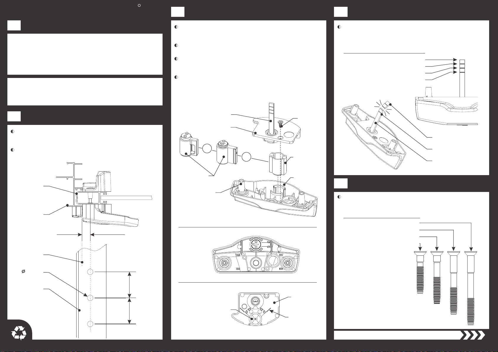
Step 8
Step 5
Figure H
'Face Fix' Catch Screw (1”)'Front Fix' Catch Screw (3/8”)
Door Jamb
Catch Assembly
Front Fix
Slot
Face Fix Slot
Adjustment
Screw
Catch Plug
Grub Screw
Catch
Plug
‘Front Fix’
Catch Screw
Catch Plate
Screws from their fully ‘screwed-in’ position three (3) full turns with the
3.0mm Hex Key. Reverse the Catch Plug Grub Screws with the 2.0mm
Hex Key and remove the Catch Plugs using a small screwdriver.
To fix the Catch Assembly to the front of the jamb, reverse the Adjustment
the lock with a 1 to 2mm gap between the lock and Catch Assembly.
Mark the centre of the 'front fix' slots and drill the jamb with a 3.5mm drill.
Close the door and position the Catch Assembly on the jamb opposite
Tighten the 'Front Fix' Catch Screws, refit the Catch Plugs and tighten
the Catch Plug Grub Screws. Be careful not to over tighten these screws.
To fix the CatchAssembly to the face of the reveal, leave the
Catch Plugs in place, mark through the ‘face fix' slots, and use the
'Face Fix' Catch Screws instead.
Use the two 'Front Fix' Catch Screws provided to fit the Catch Assembly
lightly to the jamb. Gently close the door and operate the Lever to test
the Beak engagement. Move the Catch Assembly up and down and
adjust the Catch Plate in and out to achieve the best fit.
NOTE: If required use packers provided to align catch plate
assembly with interior handle assembly.
Interior Door
enters here
or
If the Beaks of the Interior Assembly are
extended, use the Lever to retract them.
Place the Exterior Assembly onto the exterior
face of the door stile. Rotate the protruding
Spindle into a vertical position.
Remove the Handle Screws and lift the Interior
Handle off the Interior Base, place them aside.
Pass the correct length Fixing Screws through
the Interior Base and screw firmly into the
Exterior Assembly.
To install a Keyed Cylinder into the Interior
Assembly, remove and discard the Cylinder Plug
from the underside of the Interior Handle.
Place the Interior Handle over the Interior Base.
It may be necessary to rotate the Lever to find its
correct orientation. Refit the two Handle Screws.
Install the Keyed Cylinder into the Interior Handle
matching the orientation shown in Figure G.
Depress the Plunger and test the lock operation
by operating the Lever and Cylinder Key(s)
if applicable.
NOTE: Ensure the Beaks are in the retracted
position before closing the door.
While placing the Interior Base onto the interior
face of the door stile, note the following:
- Allow the protruding Spindle to enter the
receiving slot on the underside of the Interior Base.
- Locate the bosses on the underside of the
Interior Base into the holes in the door stile.
Step 6 (optional)
Step 7
Figure G
or
or
SPACERS
Timber doors with a weather
seal and some aluminium
doors require spacers between
the door and lock as shown.
Interior Handle
Handle Screw
Fixing
Screw
Cylinder Plug
Plunger
Keyed Cylinder
Beak
Lever
Interior Base
Interior
Spacer
Exterior
Spacer