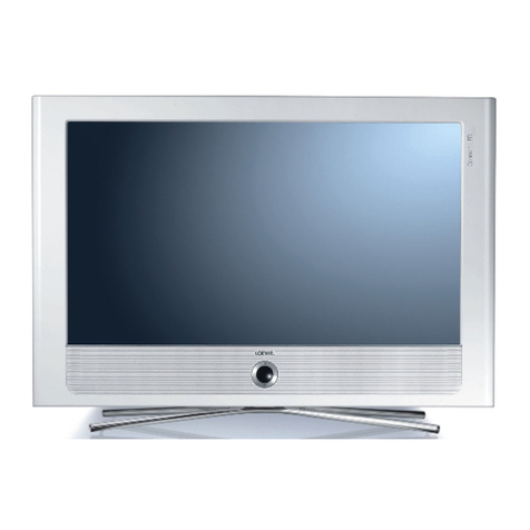
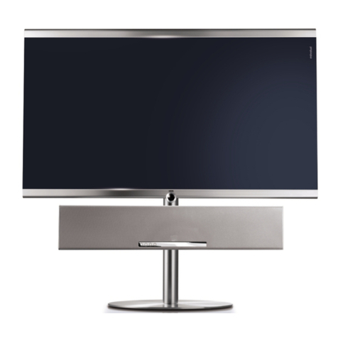
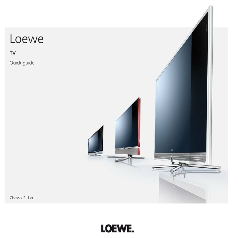
Loewe Art 32 LED DR+ / 32 LED User manual

SERVICEANLEITUNG
SL 150
Service Manual. Manuel de Service. Manuale di Servizio.
Instrucciones de servicio. Service-instructies.
230-98287.031
Art 32 LED DR+
Art.-Nr. 50412
Art 40 LED 200 DR+
Art.-Nr. 50414
Art 46 LED 200 DR+
Art.-Nr.50416
Connect 32 LED DR+
Art.-Nr. 50402
Connect 40 LED 200 DR+
Art.-Nr. 50404
Art LED 200 DR+
Connect LED 200 DR+
XELOS 32 LED 100
Art.-Nr.50422
XELOS 40 LED 100
Art.-Nr.50424

2
Inhaltsverzeichnis
Sicherheitshinweise . . . . . . . . . . . . . . . . . 3
Service Loewe Art/Connect/Xelos LED - TV: . . . . 4
Öffnen des Gerätes . . . . . . . . . . . . . . . . . 5
Entfernen der Frontscheibe . . . . . . . . . . . . . 7
Ausbau des Signalboards . . . . . . . . . . . . . 11
Ausbau des Basicboards. . . . . . . . . . . . . . 12
Verkabelung Art/Connect /Xelos LED . . . . . . . 13
Steckerbelegung Signalboard / Basicboard . . . . 33
Service Mode Befehle . . . . . . . . . . . . . . . 38
Option Bytes Tabelle . . . . . . . . . . . . . . . 39
Service Menü SL150 (LCD) . . . . . . . . . . . . 42
TV Menü SL 150 (LCD). . . . . . . . . . . . . . 46
Baugruppenübersicht . . . . . . . . . . . . . . . 65
Technische Daten Art/Connect /Xelos LED . . . . 66
LOEWE Auslandsvertretungen. . . . . . . . . . . 97
Index
Security advice . . . . . . . . . . . . . . . . . . . 3
Service Loewe Art/Connect/Xelos LED - TV:. . . . .4
Opening the TV-set . . . . . . . . . . . . . . . . . 5
Demounting the face-plate . . . . . . . . . . . . . 7
Demounting of the Signalboard. . . . . . . . . . 11
Demounting of the Basicboard . . . . . . . . . . 12
Wiring diagram Art/Connect/Xelos LED. . . . . . 13
Pin Description Signalboard / Basicboard . . . . . 33
Service Mode instructions . . . . . . . . . . . . . 38
Option Bytes chart . . . . . . . . . . . . . . . . 39
Service menu SL150 (LCD). . . . . . . . . . . . . 42
TV menu SL150 (LCD) . . . . . . . . . . . . . . . 46
Overview of components . . . . . . . . . . . . . 65
Technical data Art/Connect/Xelos LED . . . . . . 66
LOEWE foreign representations . . . . . . . . . . 97

3
D
Hinweis zum Schutz gegen Elektrostatik
1. Elektrostatisch gesicherte MOS-Arbeitsplätze.
Der Umgang mit gegen Elektrostatik empndlichen Bauteilen
muß an einem elektrostatisch gesicherten MOS-Arbeitsplatz
erfolgen. Ein elektrostatisch gesicherter MOS-Arbeitsplatz
erdet über Entladungswiderstände sämtliche leitende Ma-
terialien einschließlich der Person. Nichtleiter werden durch
Luftionisation entladen. Die Integration von Lötkolben und
Meßgeräten in den gesicherten MOS-Arbeitsplatz ist nur
mit Trenntrafo in jedem der verwendeten Geräte möglich.
Die Meßgeräte-Massen werden ebenfalls mit Entladungs-
widerständen geerdet.
2. Gesicherte Verpackung durch leitfähige Materialien.
Zum Schutz gegen Elektrostatik werden elektrisch leitende
Kunststoe für Verpackung und Transportmittel verwendet.
Leitende Kunststoe gibt es als schwarze oder transparente
Schutzbeutel, Schaumsto, Folien und als Behälter. Empnd-
liche Bauteile dürfen nur am gesicherten MOS-Arbeitsplatz
aus der Verpackung entfernt bzw. verpackt werden.
Sicherheitshinweise/Vorschriften
1. Instandsetzungen, Änderungen und Prüfung netzbetriebe-
ner elektronischer Geräte und deren Zubehör dürfen nur von
fachkundigen Personen ausgeführt werden.
2. Es gelten die Vorschriften und Sicherheitshinweise nach VDE
0701, Teil 200, und die Vorschriften und Sicherheitshinweise
des jeweiligen Landes!
3. VDE 0701, Teil 200, beinhaltet Vorschriften zur Instandset-
zung, Änderung und Prüfung netzbetriebener elektronischer
Geräte und deren Zubehör.
4. Vor der Auslieferung des Geräts muß eine Sichtprüfung des
Geräts und der Anschlußleitungen (und soweit vorhanden,
des Schutzleiters), und die Messung des Isolationswider-
standes und des Ersatz-Ableitstromes nach VDE 0701, Teil
200, durchgeführt werden. Der niederohmige Durchgang des
Schutzleiters ist durch Messung laut Vorschrift VDE 0701,
Teil 1, nachzuweisen.
5. Die Vorschriften des jeweiligen Landes sind zusätzlich zu be-
achten.
6. Bauteile mit dem Symbol gekennzeichnet, dürfen nur
durch Originalteile ersetzt werden.
GB
Note on electrostatic shielding
1. Electrostatically shielded MOS workstations
Components sensitive to electrostatic discharge must be han-
dled at workstation with electrostatic shielding. An electrostati-
cally shielded MOS workstation is tted with discharge resistor
which earth all conductive materials, including the technician
working there. Dielectrics are discharged by air ionisation. The
use of soldering irons and measuring equipment at shielded
workstation is only possible in conjunction with isolating trans-
former in each of the devices used. Measuring equipment
chassis are also earthed with discharge resistors.
2. Shielded packaging using conductive materials
To protect against electrostatic charges, electrically conductive
plastics are used for packaging and transport purposes. Con-
ductive plastics are available in the form of transparent protec-
tive bags, foam plastic, lm sheeting or containers. Sensitive
components requiring the use of protective packaging must
only be packed and unpacked at shielded workstations.
Safety warnings/regulations
1. The repair, modication and testing of mains-operated elec-
tronic devices and their accessories must only be performed
by qualied persons.
2. It is necessary to follow the regulations and safety warnings
to VDE 0701, part 200, as well as the regulations and safety
warnings applicable in the country concerned.
3. VDE 0701, Part 2, contains regulations on the repair, modica-
tion and testing of mains-operated electronic devices and their
accessories.
4. Before delivery, the device and the connecting leads (includ-
ing any protective earth conductor tted) must undergo visual
inspection, and the insulation resistance and the equivalent
leakage current must be measured according to VDE 0701,
part 200. The low-resistance continuity of the protective earth
conductor must be veried by measurement to VDE regula-
tion 0701, part 1.
5. The regulations of the country concerned must also be ob-
served.
6. Only genuine parts must be used for replacing components
marked with the symbol .
4
Service Loewe TV
• Art32/40/46LEDundLEDDR+
• Connect32/40LEDundLEDDR+
• Xelos32/40LED
Achtung!
Vermeiden Sie Schäden durch elektrostatische Auadungen.
Beachten Sie den Umgang mit MOS-Bauteilen!
Wichtig:
Achten Sie beim Arbeiten mit den Art/Connect/Xelos LED Geräten auf eine saubere und
staubfreie Arbeitsumgebung!
Gehen Sie äußerst behutsam mit den Oberächen der einzelnen Komponenten um und tra-
gen Sie bei den Arbeiten an den Art/Connect/Xelos-Produkten, die im Rahmen des Loewe
Premiumservice angebotenen Handschuhe, um Kratzer oder andere Beschädigungen der
Oberäche zu vermeiden.
Attention!
Prevent damages by electrostatic charging.
Pay attention to handling of MOS components!
Important:
Take care that your working zone is clean and free of dust!
Handle very carefully the surfaces of the components and wear the special gloves for
Loewe Premium Service, to avoid scratches and other damages on the surfaces.

5
1. TV-Gerät öffnen
Opening the TV set
Art 32/40/46 LED
Ziehen Sie den Netzstecker!
Entfernen Sie die Anschlussleitungen vom TV-Gerät.
Entfernen Sie, wenn vorhanden, das kurze Verbindungskabel zwischen den Tuneranschlüssen.
Lösen und entfernen Sie, entsprechend des TV-Gerätemodels, die auf der entsprechenden Skizze mit Pfeilen mar-
kierten Schrauben.
(Zum Einsetzen der Rückwand verfahren Sie entsprechend umgekehrt.)
Vorgehensweise
Procedure
Abb. 1
Abb. 2
Nehmen Sie die Kabelabdeckung an der Rückseite des
TV-Gerätes ab.
Abdeckung nach hinten entrasten und nach unten
wegnehmen.
Entfernen Sie die mit Pfeil markierten Schrauben auf der
Rückseite.
Das Öffnen der Schrauben a1 und a2 trifft nur auf die TV-
Geräte Art 40/46 LED zu.
Wir empfehlen zum Abnehmen/ Montieren der Geräterück-
wand/Gehäuseteile Handschuhe zu tragen.
Sie verhindern damit Fingerabdrücke/ Verunreinigungen auf
der Rückwand.
Die Rückwand kann, nachdem alle Schrauben entfernt wor-
den sind, abgenommen werden.
a1 a2
Pull out the mains plug!
Remove the connecting leads from the TV set.
Remove the short connecting cable between the tuner connections if available.
Loosen and remove the screws marked by arrows in the appropriate sketch according to the TV set model.
(Proceed in the reverse order to replace the rear panel.)
If possible, position the TV set so that it is accessible
from all sides.
Unlatch connecting cover (arrow) to the rear and
remove.
Remove the screws indicated by the arrows on the rear side.
Opening the screws a1 and a2 is applicable only for TV sets
of the 40/46 LED.
We recommend wearing gloves when removing/ mounting
the device rear panel/ housing parts.
This avoids nger prints/ impurities on the rear panel.
Once all the screws have been removed, the rear panel can
be detached.

6
2. TV-Gerät öffnen
Opening the TV set
Connect 32/40 LED
Abb. 1
Abb. 2
Ziehen Sie den Netzstecker!
Entfernen Sie die Anschlussleitungen vom TV-Gerät.
Entfernen Sie, wenn vorhanden, das kurze Verbindungskabel zwischen den Tuneranschlüssen
Lösen und entfernen Sie, entsprechend des TV-Gerätemodels, die auf der entsprechenden Skizze mit Pfeilen mar-
kierten Schrauben.
(Zum Einsetzen der Rückwand verfahren Sie entsprechend umgekehrt.)
Vorgehensweise
Procedure
Nehmen Sie die Kabelabdeckung an der Rückseite des
TV-Gerätes ab.
Abdeckung nach hinten entrasten und nach unten
wegnehmen.
Entfernen Sie die mit Pfeil markierten Schrauben auf der
Rückseite.
Das Öffnen der Schrauben a1 und a2 trifft nur auf das TV-
Gerät Connect 40 LED zu.
Wir empfehlen zum Abnehmen/ Montieren der Geräterück-
wand/Gehäuseteile Handschuhe zu tragen.
Sie verhindern damit Fingerabdrücke/ Verunreinigungen auf
der Rückwand.
Die Rückwand kann, nachdem alle Schrauben entfernt wor-
den sind, abgenommen werden.
a1 a2
Pull out the mains plug!
Remove the connecting leads from the TV set.
Remove the short connecting cable between the tuner connections if available.
Loosen and remove the screws marked by arrows in the appropriate sketch according to the TV set model.
(Proceed in the reverse order to replace the rear panel.)
If possible, position the TV set so that it is accessible
from all sides.
Unlatch connecting cover (arrow) to the rear and
remove.
Remove the screws indicated by the arrows on the rear side.
Opening the screws a1 and a2 is applicable only for the TV
set Connect 40 LED.
We recommend wearing gloves when removing mounting
the device rear panel/ housing parts.
This avoids nger prints/ impurities on the rear panel.
Once all the screws have been removed, the rear panel can
be detached.

7
Entfernen der Rückwand
Demontage der Lautsprecherboxen (je eine Schrau-
be), lösen der Kabel.
Lösen der Rahmen- / Scheibensicherung: unten
2 Halter mit Schraube, oben zwei Schrauben am
Panel (siehe auch Abb.1).
Abb. 1
Abb. 2
3. Entfernen der Frontscheibe:
Remove of front glass:
Connect 40 LED
Vorbereitung:
Gerät steht aufrecht mit dem Tischfuß.
Netzkabel, falls angeschlossen, abziehen!
Durchtrennen des EMV-Bandes links und rechts
(siehe Abb. 2, Pfeil ).
Cut the EMV tape left and right (see pict. 2, arrow)
Preparation:
Set is placed upright with table stand.
Remove mains cord if plugged in!
remove rear cover
dismount loudspeaker boxes (one screw each),
unlock cables.
Unscrew the holder for frame/glass: bottom 2
holders with screw, top two screws on panel (see
picture 1).

8
Ausschälwerkzeug in mittlerer Position
Tool in middle position
Abb. 4
Abb. 3
Ausschälwerkzeug (Aus.wzg. 90427.973) verwenden, um eine
dosierte Ablösebewegung des Panels zu ermöglichen.
Use special tool (Aus.wzg. 90427.973), to remove frame cont-
rolled from the panel.
Ausschälwerkzeug einsetzen
Insertion of tool
Aus.wzg. seitlich an der Stelle unter das Panel
schieben, wo die Vertikalrippe ausgenommen ist (in
Abb 3 wird z.B. an der rechten Geräteseite begon-
nen). Dazu die Front und das Panel vorsichtig etwas
auseinanderdrücken.
Ausschälwerkzeug wie in Abb. 3 angegeben lang-
sam (!) drehen. Dabei löst sich das wiederlösbare
NITTO-Klebeband hörbar von Panel / Scheibe ab.
Aus.wzg. weiter nach unten schieben (siehe Abb.
4) und langsam (!) drehen, bis sich das Klebeband
weiter hörbar löst.
Move special tool downwards (see picture 4) and
turn carefully so that adhesive tape releases more
and more.
Drehrichtung
Press special tool under the panel (see picture 3,
start on top of right side). Press front carefully from
panel by turning the tool (picture 3) downwards
until the removable adhesive NITTO tape releases
hearable.

9
Abb. 5
Schrittweises lösen des Panels von
oben.....
Release panel step by step.....
Abb. 6
Schrittweises lösen des Panels von unten
Release step by step from bottom
Ausschälvorgang fortsetzen, bis sich das Panel von der
Scheibe auf einer Seite gelöst hat (siehe Abb. 5 und 6).
Go on with procedure until one side of panel is remo-
ved from glass (see pict. 5 and 6)
Ausschälvorgang auf der anderen Geräteseite wieder-
holen.
Repeat procedure on other side of set.

10
Abb. 7
Lösen des Bedienteilkabels
Unplugging of cable from front keyboard
Abb. 8
Abziehen der verbrauchten Klebebänder
Remove old adhesive tapes
Nach dem Abschälen der zweiten Seite ist der Front-
rahmen vor dem Panel zu halten, um das Kabel des
Bedienteils lösen zu können (siehe Abb. 7).
Anschließend sind die verbleibenden Klebebänder auf
dem Frontrahmen/ Panel langsam(!) abzuziehen, damit
keine Rückstände kleben bleiben ( Abb. 8).
Die Flächen sind zu reinigen.
To unplug the cable from keyboard hold the Front-
frame in a certain distance to panel (see picture 7).
Remove nally the rest of old adhesive tapes from
front and panel (slowly) and clean this area (pict. 8).

11
Beachten Sie den Umgang mit MOS-Bauteilen!
Pay attention to MOS components!
4. Ausbau des Signalboards
Removal of signalboards
Art/Connect/Xelos LED
Entfernen Sie zuerst die 4 Torx-Schrauben (Größe
TX10) des Tunermoduls und ziehen Sie dieses vom
Signalboard ab ( Abb. 1 ,weiße Pfeile).
Im Anschluss lösen Sie die 4 Torx-Schrauben (Größe
TX 10) vom Kühlkörper des Signalboards ( Abb. 1,
schwarze Pfeile).
Danach entfernen Sie die beiden Bolzen der VGA-
Buchse und die beiden Torx-Schrauben (Größe TX 10)
an der Eurobuchse (Abb. 2).
Lösen Sie alle Kabelverbindungen des Signalboards
und achten Sie dabei darauf, Schäden durch elektro-
statische Auadung zu vermeiden.
Abb 1
Abb.2
Remove rst the four Torx screws (size TX 10) of the
tunermodul and unplug this from signalboard (pict.1,
white arrows).
Now unscrew the 4 Torx screws (size TX 10) from heat
sink of signalboard (picture 1, black arrows).
Now remove the two bolts from VGA socket and the
two Torx screws ( size TX 10) from Eurosocket (pict.2)
Unplug all cable connections from signalboard and
take care of electrostatic handling.

12
5. Ausbau des Basicboards
Removal of basicboards
Art/Connect/Xelos LED
Beachten Sie den Umgang mit MOS-Bauteilen!
Pay attention to MOS components!
Entfernen Sie die vier markierten Torx-Schrauben
(Größe TX 10), siehe Abbildung.
Lösen Sie alle Kabelverbindungen des Basicboards.
Achten Sie dabei darauf, Schäden durch elektrostati-
sche Auadung zu vermeiden.
Unscrew the four marked Torx screws (size TX 10), see
picture.
Unplug all cable connections from basicboard.
Take care of electrostatic handling.

13
Verdrahtungsplan / Wiring diagram Art 32 LED
Netzschalter
Main switch
32370
~230V
70656.054
70657.052
Signal-Board
70650.058
W1200
W1028
W1025
W1024
W1031
W1032 W1033 W1035 W1037
W1011
W1030
W1027
W1022
W1023
W1017
W1012
W1039
W1009
W1008
W1007
W1006
W1005
W1004
W1003
W1002
W1001
W1000 W1013
W1000
W1001
W1302
W1304
W1003
W1500
Basic-Board
71050.054
W6301
W6251
W6591
W6601
W6701
W6602
W6501
W6751
W6851
W6801
W6821
W6831
AV-Double CI
1XUSB Interface
70480.052
W1000
W1001
Audio Interface
AudioLink
70627.051
70233.055
W5031
Bedieneinheit
Control Unit
70945.050
Frontend kpl.
FET08 Single
70623.052
LCD-Controller
Panelkit
70808.001
LED Backlight
89528.060
89982.053
70278.003
70588.001
70425.002
70657.051
71046.053
71046.054
70587.001
70601.001
70816.003
70821.003
70782.002
rot
natur

14
Art 32 LED

15
Verdrahtungsplan / Wiring diagram Art 32 LED DR+
Netzschalter
Main switch
32370
~230V
70656.054
70657.052
Signal-Board
70650.056
W1200
W1028
W1024
W1031
W1032 W1033 W1035 W1037
W1011
W1030
W1027
W1022
W1023
W1017
W1012
W1039
W1009
W1008
W1007
W1006
W1005
W1004
W1003
W1002
W1001
W1000 W1013 W1025
W1000
W1001
W1302
W1304
W1003
W1500
Basic-Board
71050.054
W6301
W6251
W6591
W6601
W6701
W6602
W6501
W6751
W6851
W6801
W6821
W6831
AV-Double CI
1XUSB Interface
70480.052
W1000
W1001
Audio Interface
AudioLink
70627.051
70233.055
W5031
Bedieneinheit
Control Unit
70701.050
LCD-Controller
Panelkit
70808.001
LED Backlight
89528.060
89982.053
70278.003
70588.001
70425.002
70657.051
71046.053
71046.054
70587.001
70601.001
70816.003
70821.003
70782.002
rot
nat
Festplatte
Hard disc
34124.063
70660.001
70941.002
Frontend kpl.
FET08 Twin
70319.055

16
Art 32 LED DR+

17
Verdrahtungsplan / Wiring diagram Art 40 LED 200
Netzschalter
Main switch
32370
~230V
70656.054
70657.057
Signal-Board
70650.057
W1200
W1028
W1025
W1024
W1031
W1032 W1033 W1035 W1037
W1011
W1030
W1027
W1022
W1023
W1017
W1012
W1039
W1009
W1008
W1007
W1006
W1005
W1004
W1003
W1002
W1001
W1000 W1013
W1000
W1001
W1302
W1304
W1013
W1500
Basic-Board
71050.052
W6301
W6251
W6591
W6601
W6701
W6602
W6501
W6751
W6851
W6801
W6821
W6831
AV -Double CI
1XUSB Interface
70480.052
W1000
W1001
Audio Interface
AudioLink
70627.051
70233.055
W5031
Bedieneinheit
Control Unit
70945.050
Frontend kpl.
FET08 Single
70623.052
LCD-Controller
Panelkit
70806.001
LED Backlight
89528.060
89982.053
70278.003
70588.004
70425.005
70657.056
71046.053
71046.054
70587.001
70601.002
70816.001
70821.001
70782.002
nat
rot

18
Art 40 LED 200

19
Verdrahtungsplan / Wiring diagram Art 40 LED 200 DR+
Netzschalter
Main switch
32370
~230V
70656.054
70657.057
Signal-Board
70650.056
W1200
W1028
W1025
W1024
W1031
W1032 W1033 W1035 W1037
W1011
W1030
W1027
W1022
W1023
W1017
W1012
W1039
W1009
W1008
W1007
W1006
W1005
W1004
W1003
W1002
W1001
W1000 W1013
W1000
W1001
W1302
W1304
W1003
W1500
Basic-Board
71050.052
W6301
W6251
W6591
W6601
W6701
W6602
W6501
W6751
W6851
W6801
W6821
W6831
AV-Double CI
1XUSB Interface
70480.052
W1000
W1001
Audio Interface
AudioLink
70627.051
70233.055
W5031
Bedieneinheit
Control Unit
70701.050
Frontend kpl.
FET08 Twin
70319.055
Festplatte
Hard disc
34124.063
LCD-Controller
Panelkit
70806.001
LED Backlight
89528.060
89982.053
70278.003
70588.004
70425.005
70657.056
71046.053
71046.054
70587.001
70601.002
70816.001
70821.001
70660.001
70941.002
70782.002
rot
nat

20
Art 40 LED 200 DR+
Other manuals for Art 32 LED DR+ / 32 LED
1
This manual suits for next models
13
Table of contents
Languages:
Other Loewe LED TV manuals

Loewe
Loewe Xelos 32 LED User manual

Loewe
Loewe SL1 Series User manual

Loewe
Loewe Individual 40 Selection LED 200 User manual

Loewe
Loewe Connect User manual

Loewe
Loewe Art 40 LED 200 User manual

Loewe
Loewe bild v.65 dr+ User manual

Loewe
Loewe Connect 32 LED DR+ User manual

Loewe
Loewe Individual 40 Compose LED DR+3D User manual

Loewe
Loewe Individual 32 Selection User manual

Loewe
Loewe Art 32 LED DR+ / 32 LED User manual