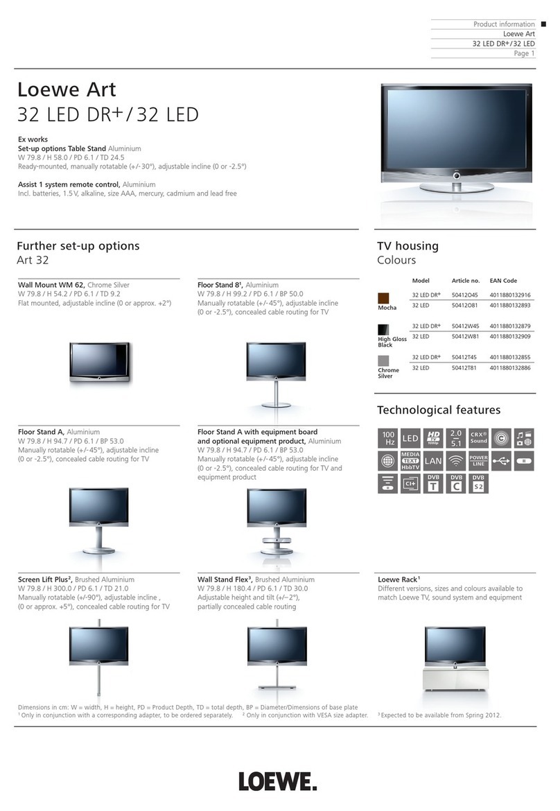
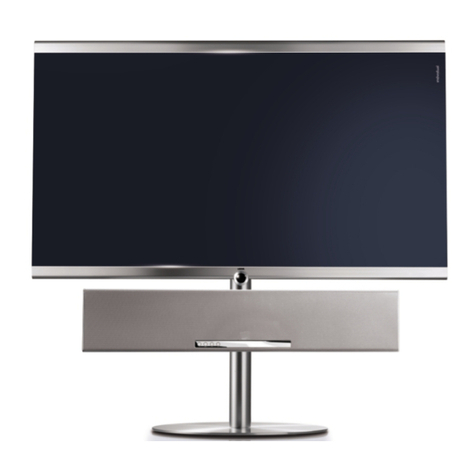
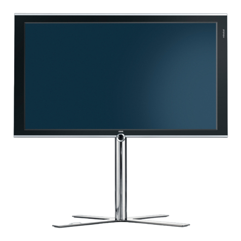
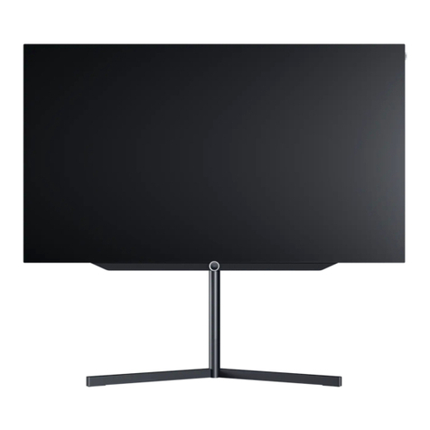
Loewe Individual 40 Compose LED DR+3D User manual

SERVICEANLEITUNG
Service Manual. Manuel de Service. Manuale di Servizio.
Instrucciones de servicio. Service-instructies.
SL 151
230-98287.036
Individual 40
Compose LED DR+3D
Art.-Nr. 50430
Individual 46
Compose LED DR+3D
Art.-Nr. 50431
Individual 55
Compose LED DR+3D
Art.-Nr. 50432

2
Inhaltsverzeichnis
Sicherheitshinweise . . . . . . . . . . . . . . . . . 3
Service Loewe Compose LED 3D - TV:. . . . . . . .4
Öffnen des Gerätes . . . . . . . . . . . . . . . . . 5
Demontage des Infrarotauges. . . . . . . . . . . .8
Ausbau des Signalboards . . . . . . . . . . . . . 15
Ausbau des Basicboards. . . . . . . . . . . . . . 17
Verkabelung Compose LED 3D . . . . . . . . . . 18
Steckerbelegung Sb. / Bb. / Booster . . . . . . . . 24
Service Mode Befehle . . . . . . . . . . . . . . . 30
Option Bytes Tabelle . . . . . . . . . . . . . . . 31
Service Menü SL151 (LCD) . . . . . . . . . . . . 42
TV Menü SL 151 (LCD). . . . . . . . . . . . . . 45
Baugruppenübersicht . . . . . . . . . . . . . . . 64
Technische Daten Compose LED 3D. . . . . . . . 65
3D FAQ . . . . . . . . . . . . . . . . . . . . . . 92
LOEWE Auslandsvertretungen. . . . . . . . . . . 96
Index
Security advice . . . . . . . . . . . . . . . . . . . 3
Service Loewe Compose LED 3D - TV: . . . . . . . 4
Opening the TV-set . . . . . . . . . . . . . . . . . 5
Removal of IR eye. . . . . . . . . . . . . . . . . .8
Dismounting of the Signalboard . . . . . . . . . 15
Dismounting of the Basicboard . . . . . . . . . . 17
Wiring diagram Compose LED 3D. . . . . . . . . 18
Pin Description Sb. / Bb./ Booster . . . . . . . . . 24
Service Mode instructions . . . . . . . . . . . . . 30
Option Bytes chart . . . . . . . . . . . . . . . . 31
Service menu SL151 (LCD). . . . . . . . . . . . . 42
TV menu SL151 (LCD) . . . . . . . . . . . . . . . 45
Overview of components . . . . . . . . . . . . . 64
Technical data Compose LED 3D . . . . . . . . . 65
3D FAQ . . . . . . . . . . . . . . . . . . . . . . 92
LOEWE foreign representations . . . . . . . . . . 96

3
D
Hinweis zum Schutz gegen Elektrostatik
1. Elektrostatisch gesicherte MOS-Arbeitsplätze.
Der Umgang mit gegen Elektrostatik empndlichen Bauteilen
muß an einem elektrostatisch gesicherten MOS-Arbeitsplatz
erfolgen. Ein elektrostatisch gesicherter MOS-Arbeitsplatz
erdet über Entladungswiderstände sämtliche leitende Ma-
terialien einschließlich der Person. Nichtleiter werden durch
Luftionisation entladen. Die Integration von Lötkolben und
Meßgeräten in den gesicherten MOS-Arbeitsplatz ist nur
mit Trenntrafo in jedem der verwendeten Geräte möglich.
Die Meßgeräte-Massen werden ebenfalls mit Entladungs-
widerständen geerdet.
2. Gesicherte Verpackung durch leitfähige Materialien.
Zum Schutz gegen Elektrostatik werden elektrisch leitende
Kunststoe für Verpackung und Transportmittel verwendet.
Leitende Kunststoe gibt es als schwarze oder transparente
Schutzbeutel, Schaumsto, Folien und als Behälter. Empnd-
liche Bauteile dürfen nur am gesicherten MOS-Arbeitsplatz
aus der Verpackung entfernt bzw. verpackt werden.
Sicherheitshinweise/Vorschriften
1. Instandsetzungen, Änderungen und Prüfung netzbetriebe-
ner elektronischer Geräte und deren Zubehör dürfen nur von
fachkundigen Personen ausgeführt werden.
2. Es gelten die Vorschriften und Sicherheitshinweise nach VDE
0701, Teil 200, und die Vorschriften und Sicherheitshinweise
des jeweiligen Landes!
3. VDE 0701, Teil 200, beinhaltet Vorschriften zur Instandset-
zung, Änderung und Prüfung netzbetriebener elektronischer
Geräte und deren Zubehör.
4. Vor der Auslieferung des Geräts muß eine Sichtprüfung des
Geräts und der Anschlußleitungen (und soweit vorhanden,
des Schutzleiters), und die Messung des Isolationswider-
standes und des Ersatz-Ableitstromes nach VDE 0701, Teil
200, durchgeführt werden. Der niederohmige Durchgang des
Schutzleiters ist durch Messung laut Vorschrift VDE 0701,
Teil 1, nachzuweisen.
5. Die Vorschriften des jeweiligen Landes sind zusätzlich zu be-
achten.
6. Bauteile mit dem Symbol gekennzeichnet, dürfen nur
durch Originalteile ersetzt werden.
GB
Note on electrostatic shielding
1. Electrostatically shielded MOS workstations
Components sensitive to electrostatic discharge must be han-
dled at workstation with electrostatic shielding. An electrostati-
cally shielded MOS workstation is tted with discharge resistor
which earth all conductive materials, including the technician
working there. Dielectrics are discharged by air ionisation. The
use of soldering irons and measuring equipment at shielded
workstation is only possible in conjunction with isolating trans-
former in each of the devices used. Measuring equipment
chassis are also earthed with discharge resistors.
2. Shielded packaging using conductive materials
To protect against electrostatic charges, electrically conductive
plastics are used for packaging and transport purposes. Con-
ductive plastics are available in the form of transparent protec-
tive bags, foam plastic, lm sheeting or containers. Sensitive
components requiring the use of protective packaging must
only be packed and unpacked at shielded workstations.
Safety warnings/regulations
1. The repair, modication and testing of mains-operated elec-
tronic devices and their accessories must only be performed
by qualied persons.
2. It is necessary to follow the regulations and safety warnings
to VDE 0701, part 200, as well as the regulations and safety
warnings applicable in the country concerned.
3. VDE 0701, Part 2, contains regulations on the repair, modica-
tion and testing of mains-operated electronic devices and their
accessories.
4. Before delivery, the device and the connecting leads (includ-
ing any protective earth conductor tted) must undergo visual
inspection, and the insulation resistance and the equivalent
leakage current must be measured according to VDE 0701,
part 200. The low-resistance continuity of the protective earth
conductor must be veried by measurement to VDE regula-
tion 0701, part 1.
5. The regulations of the country concerned must also be ob-
served.
6. Only genuine parts must be used for replacing components
marked with the symbol .
4
Service Loewe TV
• Compose40/46LEDDR+3D
• Compose40HotelLED3D
• Compose55LEDDR+3D
Achtung!
Vermeiden Sie Schäden durch elektrostatische Auadungen.
Beachten Sie den Umgang mit MOS-Bauteilen!
Wichtig:
Achten Sie beim Arbeiten mit den Compose-LED Geräten auf eine saubere und staubfreie
Arbeitsumgebung!
Gehen Sie äußerst behutsam mit den Oberächen der einzelnen Komponenten um und tra-
gen Sie bei den Arbeiten an den Compose-Produkten die im Rahmen des Loewe Premium-
service angebotenen Handschuhe, um Kratzer oder andere Beschädigungen der Oberäche
zu vermeiden.
Attention!
Prevent damages by electrostatic charging.
Pay attention to handling of MOS components!
Important:
Take care that your working zone is clean and free of dust!
Handle very carefully the surfaces of the components and wear the special gloves for
Loewe Premium Service, to avoid scratches and other damages on the surfaces.

5
1. TV-Gerät öffnen
Opening the TV set
Compose 40/46/55 3D
Ziehen Sie den Netzstecker!
Entfernen Sie die Anschlussleitungen vom TV-Gerät.
Lösen und entfernen Sie, entsprechend des TV-Gerätemodels, die auf der entsprechenden Skizze mit Pfeilen
markierten Schrauben.
(Zum Einsetzen der Rückwand verfahren Sie entsprechend umgekehrt.)
Vorgehensweise
Procedure
Abb. 1
Abb. 2
Nehmen Sie die Kabelabdeckung an der Rückseite des
TV-Gerätes ab.
Abdeckung nach hinten entrasten und nach unten
wegnehmen.
Pull out the mains plug!
Remove the connecting leads from the TV set.
Loosen and remove the screws marked by arrows in the appropriate sketch according to the TV set model.
(Proceed in the reverse order to replace the rear panel.)
Unlatch connecting cover (arrow) to the rear and
remove.
Stellen Sie das TV-Gerät, wenn möglich so,dass es von
allen Seiten zugänglich ist.
If possible, position the TV set so that it is accessible
from all sides.
Als Beispiel beschrieben am TV-Gerät Individual 40 Compose 3D
Explained on an Individual 40 Compose 3D

6
Abb. 3
Abb. 4
Abb.5
Hier der geöffnete Kabelanschlußbereich.
Opened connecting terminal.
Unter den seitlichen Intarsien benden sich rechts und links
je zwei Halteschrauben(Schrauben M3 T10), die entfernt
werden müssen.
Nehmen Sie die Intarsien, die durch Magnetkraft gehalten
werden, ab. Verwenden sie nach Möglichkeit den Fingerna-
gel oder ein geeignetes Hilfsmittel, wie Plastikkarte oder
kleinen Sauger. Abb.4
Under the inlays left and right side you nd two screws
M3 T10. To remove the magnetic inlays use ngernail or
plastic card. ( picture 4 )
Abb. 5, Pfeile, kennzeichnet die Position der zu entfernenden
Schrauben unter den Intarsien rechts und links am TV-Gerät.
Picture 5, arrows, shows the position of the xing screws
under the inlays.

7
Abb. 6
Ist unter Ihrem TV-Gerät ein Lautsprecher montiert, so muß dieser entfernt werden. Der Lautsprecher verdeckt den
Zugang zur Halteschraube (Bedienauge/ Gerätefront)
Demontieren des Lautsprechers
4 Schrauben entfernen, siehe Abb. 6, Pfeile. Lautsprecher nach hinten aus den Gummipufferhaltern nehmen.
If a speaker box is mounted under TV it has to be removed. This is necessaty because it covers the xing screw of the
infrared receiver.
Removal of loadspeaker box
Remove the 4 screws marked in picture 6,arrows. Pull out speaker from the rubber support.

8
Abb. 8
Abb. 7
2. Demontage des Infrarotauges
Removal of IR eye
Achtung:
Im Anschluss das Bedienteilkabel sehr vorsichtig von der ligran verlöteten Bedien-
teilbuchse abziehen. Bei der Montage des Infrarotauges ist das 11pol. Bedienteilkabel
nach aufstecken unbedingt nach rechts zurück ins Gerät zu schieben, damit das Kabel
nicht von der Schraube zur Befestigung des Infrarotauges beschädigt werden kann,
Abb. 8.
Attention:
Please unplug very carefully the 11pole connector from the IR eye. For installing IR
eye plug on the cable and place rest of cable tree in to right side of tv frame to avoid
damage of cable tree by xing IR eye with screw.( picture 8 )
Das von unten am Frontrahmen befestigte Infrarotauge mit einer Torx-Schraube vom Typ M4 T15
abschrauben, Abb. 7.
The IR eye is xed with a Torx screw M4 T15 on bottom frame of TV. Remove screw, see picture 7.

9
Abb. 9
Abb. 10
Abb. 9, Pfeil, entfernen Sie diese Schraube,
Bedienauge und Gerätefront sind von einander
gelöst.
Pictur 9,arrow, remove the screw to unlock IR eye from
front frame.
Zum Bedienauge geht ein Kabel, dessen Stecker
(Abb. 10) ist vom Bedienauge abzuziehen.
Remove carefully the 11pole connector from IR eye
( picture 10 )
Abb. 11
Ziehen Sie den Frontrahmen am unteren Ende zu sich
hin und hängen ihn nach oben aus.
Achten Sie später beim Zusammenbau darauf, dass
Sie das Kabel des Bedienauges nicht einklemmen und
durch die Öffnung in der Gerätefront fädeln.
Pull the front frame on the lower edge towards your-
self and lift it up to unhook.
For installation of front frame thread the cable tree
through hole for IR eye. Take care that cable is not
pinched by front frame.
Abb. 12
Gerätefront abnehmen und an einem sicheren Ort
lagern (vor Beschädigung geschützt lagern).
Please front frame protected from dust and mechanical
damage.

10
Abb. 13
Die Rückwand des TV-Gerätes (wie im Bei-
spiel Individual 40 Selection LED 200 DR)
wird auch von den mit Pfeil auf der Vordersei-
te markierten Schrauben gehalten.
Diese Schrauben sind zu entfernen.
Abb. 14
Entfernen Sie die mit Pfeil markierten Schrau-
ben auf der Rückseite.
Abb. 15
Unter dieser Klappe befinden sich zwei
Schrauben, die entfernt werden müssen.
Um den Zugang zu den Schrauben zu erleich-
tern, rasten Sie diese Klappe aus.
(Klappe etwas öffnen und seitlich nach hinten
ziehen)
Entfernen Sie die mit Pfeil markierten Schrau-
ben.
( Informationen über den Sitz der zu entfernenden
Schrauben der entsprechenden Gerätevariante
erhalten Sie am Ende der Demontageanleitung.)
Die Rückwand des TV-Gerätes (wie im Beispiel
Individual 40 Selection LED 200 DR) wird auch von den
mit Pfeil auf der Vorderseite markierten Schrauben ge-
halten.(Informationen über den Sitz der zu den entfer-
nenden Schrauben der entsprechenden Gerätevariante
erhalten Sie am Ende der Demontageanleitung.)
Diese Schrauben sind zu entfernen.
The rear cover of TV is xed with the screws from the
front. See arrows in picture 13.
Remove the screws.
Entfernen Sie die mit Pfeil markierten Schrauben auf
der Rückseite.
Remove the marked screws (arrows) from rear cover.
Unter dieser Klappe benden sich zwei Schrauben, die
entfernt werden müssen.
Um den Zugang zu den Schrauben zu erleichtern,
rasten Sie diese Klappe aus. (Klappe etwas öffnen und
seitlich nach hinten ziehen)
Entfernen Sie die mit Pfeil markierten Schrauben.
Under the side cover are two screws to remove. Un-
latch the cover by pulling it backwards to remove the
screws.( arrows )
Abb. 13
Abb. 14
Abb. 15

11
Die Rückwand kann, nachdem alle Schrauben entfernt
worden sind, abgenommen werden.
Remove rear cover, when all screws are removed.
Der Blick in das Innere des TV-Gerätes ist nun frei, wie
auf Abb. 17 dargestellt.
Picture 17 shows electronic inside TV.
Abb. 16
Abb. 17

12
Individual 40 Compose 3D
Abb 21
Abb 22

13
Individual 46 Compose 3D
Abb 23
Abb 24

14
Abb 25
Abb 26
Individual 55 Compose 3D

15
Beachten Sie den Umgang mit MOS-Bauteilen!
Pay attention to handling of MOS components!
3. Ausbau des Signalboards
Dismounting of signalboard
Compose 3D
Abb 18
Ausbau des Signalboards
Entfernen Sie zuerst die 6 Torx-Schrauben vom Typ M3 T10 und ziehen Sie das Tunermodul
vom Signal-Board ab (weiße Pfeile). Im Anschluss die 4 Torx-Schrauben vom Typ M3 T10 vom
Kühlkörper des Signal-Board entfernen (schwarze Pfeile).
Dismounting of signalboard
Remove rst the 6 Torx screws M3 T10 from the tunerboard and unplug tunermodul from
signalboard (white arrows). Remove 4 Torx screws M3 T10 from the corners of heat sink (black
arrows)..

16
Abb.19
Danach die beiden Bolzen für die VGA Buchse und die 2 Torx-Schrauben an der Eurobuchse
vom Typ M3 T10 entfernen.
Lösen Sie danach alle Kabelverbindungen vom Signal-Board und vermeiden Sie dabei Schäden
durch elektrostatische Auadung.
Unplug the two bolts which x the VGA connector and the two Torx M3 T10 from the scart
socket.
Unplug all cable trees from signalboard and avoid static damage. Attention MOS-handling.

17
Remove the four Torx screws M3 T10 from basicboard and unplug all cable trees (see arrows). Prevent damages
by electrostatic charging.
Entfernen Sie die vier Torx-Schrauben vom Typ M3 T10, siehe Pfeile. Lösen Sie danach alle Kabelverbindungen
vom Basicboard und vermeiden Sie dabei Schäden durch elektrostatische Auadung.
Beachten Sie den Umgang mit MOS-Bauteilen!
Pay attention to handling of MOS components!
4. Ausbau des Basicboards
Dismounting of basicboard
Compose 3D
Abb.20

18
Verdrahtungsplan / Wiring diagram Individual 40 Compose LED DR+3D Var.44/48
Netzschalter
Main switch
32370
~230V
71139.001
70657.054
Signal Board
70800.052
W3000
W2053
W1025
W1031
W1032 W1033 W1035 W1037
W1011
W1030
W1027
W1022
W1023
W1017
W1012
W1039
W1009
W1008
W1007
W1006
W1005
W1004
W1003
W1002
W1001
W1000 W1013
W1000
W1011
W1002
W1004
W1003
W1006
W1005
Basicboard
71150.053
W6301
W6251
W6591
W6601
W6701
W6602
W6501
W6751
W6851
W6801
W6821
W6831
AV-Double CI
1XUSB Interface
70480.052
W1000
W1001
Audio Interface
AudioLink
70627.051
70233.055
W5031
Bedieneinheit
Control Unit
71701.070
W1004
W1006
W1033
LED Booster
UNIT 40/46z
71201.060
W1013
W1902
W1028
W1002
WLAN
70830.001
Frontend FET08 Twin
70319.055
Festplatte Hard disc
2.5z 500GB SATA
34123.070
Frontend FES08 Twin
70286.055
LCD 3DLE 200 FHD
Panelkit kpl.
mit LCD
71056.001
Variante 44:
71232.001
Variante 48:
71095.001
89528.057
89982.058
WLAN-Antenne
71023.001
WLAN-Antenne
71023.001
WLAN-Antenne
71023.001
70278.004
70941.001
70657.053
70787.051
70587.002
70801.001
71129.001
W1004
W1003
RJ12 MU IR
70493.050
W1001
W
1005
W
1003
W1004
71083.051
LED-Connector
Interface
71112.050
85855.079
88247.092
88247.093
orange
grau
70795.001
70816.002
70833.001
70588.002
70425.003
70656.052

19
Individual 40 Compose LED DR+3D

20
Verdrahtungsplan / Wiring diagram Individual 46 Compose LED DR+3D Var.44/48
Netzschalter
Main switch
32370
~230V
71139.001
70657.054
Signal Board
70780.052
W3000
W2053
W1025
W1031
W1032 W1033 W1035 W1037
W1011
W1030
W1027
W1022
W1023
W1017
W1012
W1039
W1009
W1008
W1007
W1006
W1005
W1004
W1003
W1002
W1001
W1000 W1013
W1000
W1011
W1002
W1004
W1003
W1006
W1005
Basicboard
71150.050
W6301
W6251
W6591
W6601
W6701
W6602
W6501
W6751
W6851
W6801
W6821
W6831
AV-Double CI
1XUSB Interface
70480.052
W1000
W1001
Audio Interface
AudioLink
70627.051
70233.055
W5031
Bedieneinheit
Control Unit
71701.070
W1004
W1006
W1033
LED Booster
UNIT 40/46z
71201.060
W1013
W1902
W1028
W1002
WLAN
70830.001
Frontend FET08 Twin
70319.055
Festplatte Hard disc
2.5z 500GB SATA
34123.070
Frontend FES08 Twin
70286.055
LCD 3DLE 200 FHD
Panelkit kpl.
mit LCD
71056.001
Var. 44:
71231.001
Var. 48:
71096.001
89528.059
89982.059
WLAN-Antenne
70872.003
WLAN-Antenne
70872.002
WLAN-Antenne
70872.002
70278.004
70941.001
70657.055
70787.051
70587.002
70801.001
71129.001
W1004
W1003
RJ12 MU IR
70493.050
W1001
W
1005
W
1003
W1004
350mm
210mm
210mm
71083.051
LED-Connector
Interface
71112.050
85855.079
88247.094
88247.093
orange
grau
70795.001
70816.001
70833.001
70588.003
70425.004
70656.053
This manual suits for next models
5
Other Loewe LED TV manuals

Loewe
Loewe bild v.65 dr+ User manual

Loewe
Loewe Individual 32 Selection User manual

Loewe
Loewe Connect User manual

Loewe
Loewe SL1 Series User manual

Loewe
Loewe Individual 26 Selection User manual

Loewe
Loewe bild i.65 dr+ set User manual

Loewe
Loewe Individual 40 Selection LED 200 User manual

Loewe
Loewe Individual COMP 40 FHD+ 100 User manual

Loewe
Loewe Connect 32 LED DR+ User manual

Loewe
Loewe Art 32 LED DR+ / 32 LED User manual