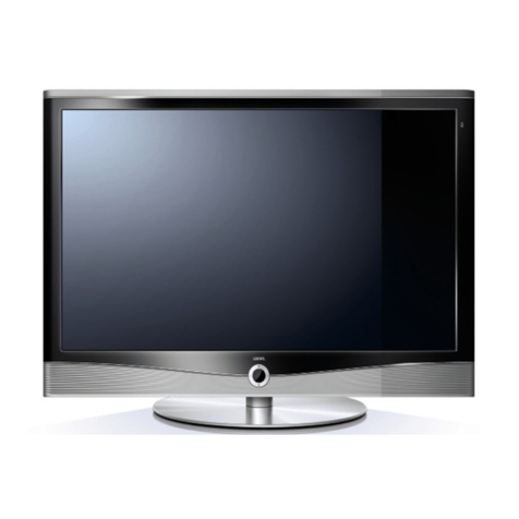
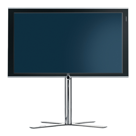
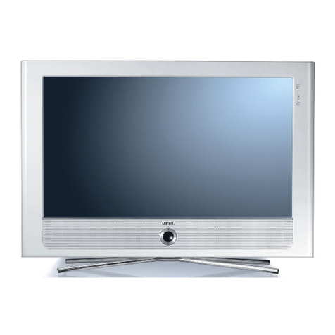
Loewe Individual COMP 40 FHD+ 100 User manual

SERVICEANLEITUNG
Service Manual. Manuel de Service. Manuale di Servizio.
Instrucciones de servicio. Service-instructies.
Individual COMP 46 FHD+ 100
Art.-Nr. 67439
Individual COMP 52 FHD+ 100
Art.-Nr. 67440
Individual COMP 40 FHD+ 100
Art.-Nr. 67437
Individual SEL 32 HD+ 100
Art.-Nr. 67441
Individual SEL 40 HD+ 100
Art.-Nr. 67442
Individual SEL 46 HD+ 100
Art.-Nr. 67443
230-98287.015
L 2710
Individual COMP 52 HD+ 100 67440
Individual SEL 46 HD+ 100 67443 Individual SEL 40 HD+ 100 67442

2
Inhaltsverzeichnis
Sicherheitshinweise . . . . . . . . . . . . . . . . . . . . . 5
TV-Gerät öffnen . . . . . . . . . . . . . . . . . . . . . . . . 8
Demontage der Demontage der Intarsien . . . . . . . . . 10
Demontage der Frontscheibe . . . . . . . . . . . . . . . 12
Verkabelung Individual Compose 40 HD+ 100/DR+ . . . 13
Verkabelung Individual Compose 52 HD+ 100/DR+ . . . 14
Verkabelung Individual Compose 46 HD+ 100/DR+ . . . 15
Verkabelung Individual 46 SEL HD+ 100/DR+. . . . . . . 16
Verkabelung Individual 46 SEL HD+ 100 . . . . . . . . . 17
Verkabelung Individual 40 SEL HD+ 100 . . . . . . . . . 18
Verkabelung Individual 32 SEL HD+ 100/DR+. . . . . . . 19
Verkabelung Individual 32 SEL HD+ 100 . . . . . . . . . 20
Steckerbelegung Signal Board . . . . . . . . . . . . . . 21
Steckerbelegung Basic Board . . . . . . . . . . . . . . . 24
Service Mode Befehle . . . . . . . . . . . . . . . . . . . 25
Option Bytes Tabelle COMP/SEL . . . . . . . . . . . . . 26
Service Menü L2710 (LCD) . . . . . . . . . . . . . . . . . 32
TV Menü . . . . . . . . . . . . . . . . . . . . . . . . . . . 34
EPG Menü . . . . . . . . . . . . . . . . . . . . . . . . . . 39
MediaNetwork / MusicBox . . . . . . . . . . . . . . . . . 40
Farbtastenbelegung . . . . . . . . . . . . . . . . . . . . 48
Baugruppenübersicht . . . . . . . . . . . . . . . . . . . 50
Technische Daten Individual COMP . . . . . . . . . . . . 51
Technische Daten Individual SEL . . . . . . . . . . . . . 57
Schaltbilder / Leiterplatten . . . . . . . . . . . . . . . . . 63
LOEWE-Niederlassungen & Auslandsvertretungen . . . 89
Table of Contents
Safety precautions . . . . . . . . . . . . . . . . . . . . . . 5
Opening the TV set . . . . . . . . . . . . . . . . . . . . . . 8
Removing the Trims . . . . . . . . . . . . . . . . . . . . 10
Removal of the front glass . . . . . . . . . . . . . . . . . 12
Wiring diagram Individual Compose 40 HD+ 100/DR+ . . 13
Wiring diagram Individual Compose 52 HD+ 100/DR+ . . 14
Wiring diagram Individual Compose 46 HD+ 100/DR+ . . 15
Wiring diagram Individual 46 SEL HD+ 100/DR+ . . . . . 16
Wiring diagram Individual 46 SEL HD+ 100 . . . . . . . . 17
Wiring diagram Individual 40 SEL HD+ 100 . . . . . . . . 18
Wiring diagram Individual 32 SEL HD+ 100/DR+ . . . . . 19
Wiring diagram Individual 32 SEL HD+ 100 . . . . . . . . 20
Pin description Signal Board . . . . . . . . . . . . . . . 21
Pin description Basic Board . . . . . . . . . . . . . . . . 24
Service Mode commands . . . . . . . . . . . . . . . . . 25
Option Bytes table COMP/SEL. . . . . . . . . . . . . . . 26
Service Menu L2710 (LCD) . . . . . . . . . . . . . . . . . 32
TV Menu . . . . . . . . . . . . . . . . . . . . . . . . . . . 41
EPG Menu . . . . . . . . . . . . . . . . . . . . . . . . . . 46
MediaNetwork / MusicBox . . . . . . . . . . . . . . . . . 47
Functions of colour keys. . . . . . . . . . . . . . . . . . 49
Components chart . . . . . . . . . . . . . . . . . . . . . 50
Technical specifications Individual COMP . . . . . . . . 52
Technical specifications Individual SEL . . . . . . . . . 58
Schematics / P.C.B . . . . . . . . . . . . . . . . . . . . . 63
LOEWE establishments & foreign representations . . . 89

3
Table des matières
Consignes de sécurité . . . . . . . . . . . . . . . . . . . . 6
Ouverture du téléviseur . . . . . . . . . . . . . . . . . . . 8
Démontage des éléments d‘habillage . . . . . . . . . . . 10
Démontage du vitre anti-reflet . . . . . . . . . . . . . . . 12
Plan de Câblage Individual Compose 40 HD+ 100/DR+ . 13
Plan de Câblage Individual Compose 52 HD+ 100/DR+ . 14
Plan de Câblage Individual Compose 46 HD+ 100/DR+ . 15
Plan de Câblage Individual 46 SEL HD+ 100/DR+ . . . . 16
Plan de Câblage Individual 46 SEL HD+ 100 . . . . . . . 17
Plan de Câblage Individual 40 SEL HD+ 100 . . . . . . . 18
Plan de Câblage Individual 32 SEL HD+ 100/DR+ . . . . 19
Plan de Câblage Individual 32 SEL HD+ 100 . . . . . . . 20
Pin description Signal Board . . . . . . . . . . . . . . . 21
Pin description Basic Board . . . . . . . . . . . . . . . . 24
Instructions du mode service . . . . . . . . . . . . . . . 25
Tableau Option Byte COMP/SEL. . . . . . . . . . . . . . 26
Menu de Service L2710 (LCD) . . . . . . . . . . . . . . . 32
Menu TV . . . . . . . . . . . . . . . . . . . . . . . . . . . 41
Menu EPG . . . . . . . . . . . . . . . . . . . . . . . . . . 46
MediaNetwork / MusicBox . . . . . . . . . . . . . . . . . 47
Fonctions des boutons de couleur . . . . . . . . . . . . 49
Correspondances des modules . . . . . . . . . . . . . . 50
Caractéristiques techniques Individual COMP . . . . . . 53
Caractéristiques techniques Individual SEL . . . . . . . 59
Schéma et Platine. . . . . . . . . . . . . . . . . . . . . . 63
Succursale LOEWE & représentation à l‘étranger . . . . 89
Indice
Norme di sicurezza . . . . . . . . . . . . . . . . . . . . . . 6
Apertura dell‘apparecchio TV . . . . . . . . . . . . . . . . 8
Rimozione degli intarsi . . . . . . . . . . . . . . . . . . . 10
Per togliere il vetro . . . . . . . . . . . . . . . . . . . . . 12
Schema connessioni Individual Compose 40 HD+ 100/DR+. . . 13
Schema connessioni Individual Compose 52 HD+ 100/DR+. . . 14
Schema connessioni Individual Compose 46 HD+ 100/DR+. . . 15
Schema connessioni
Individual 46 SEL HD+ 100/DR+ . . . 16
Schema connessioni
Individual 46 SEL HD+ 100 . . . . . . 17
Schema connessioni
Individual 40 SEL HD+ 100 . . . . . . 18
Schema connessioni
Individual 32 SEL HD+ 100/DR+ . . . 19
Schema connessioni
Individual 32 SEL HD+ 100 . . . . . . 20
Pin description Signal Board . . . . . . . . . . . . . . . 21
Pin description Basic Board . . . . . . . . . . . . . . . . 24
Comandi dell modo di servizio. . . . . . . . . . . . . . . 25
Tabella byte delle opzioni COMP/SEL . . . . . . . . . . . 26
Menu di servizio L2710 (LCD) . . . . . . . . . . . . . . . 32
Menu TV . . . . . . . . . . . . . . . . . . . . . . . . . . . 41
Menu EPG . . . . . . . . . . . . . . . . . . . . . . . . . . 46
MediaNetwork / MusicBox . . . . . . . . . . . . . . . . . 47
Funzione tasto colore . . . . . . . . . . . . . . . . . . . 49
Ordinamento dei gruppi . . . . . . . . . . . . . . . . . . 50
Dati tecnici Individual COMP. . . . . . . . . . . . . . . . 54
Dati tecnici Individual SEL . . . . . . . . . . . . . . . . . 60
Scheme e piastre . . . . . . . . . . . . . . . . . . . . . . 63
Succursale LOEWE & rappresentanza all‘estero . . . . . 89

4
Tabla de contenido
Normas de seguridad. . . . . . . . . . . . . . . . . . . . . 7
Apertura del televisor . . . . . . . . . . . . . . . . . . . . 8
Retirar las piezas laterales . . . . . . . . . . . . . . . . . 10
Desmontaje de los cristal frontal . . . . . . . . . . . . . 12
Esquema de conexiones Individual Compose 40 HD+ 100/DR+ 13
Esquema de conexiones Individual Compose 52 HD+ 100/DR+ 14
Esquema de conexiones Individual Compose 46 HD+ 100/DR+ 15
Esquema de conexiones
Individual 46 SEL HD+ 100/DR+ . 16
Esquema de conexiones
Individual 46 SEL HD+ 100 . . . . 17
Esquema de conexiones
Individual 40 SEL HD+ 100 . . . . 18
Esquema de conexiones
Individual 32 SEL HD+ 100/DR+ . 19
Esquema de conexiones
Individual 32 SEL HD+ 100/DR+ . 20
Pin description Signal Board . . . . . . . . . . . . . . . 21
Pin description Basic Board . . . . . . . . . . . . . . . . 24
Comandos del modo Service . . . . . . . . . . . . . . . 25
Tabla de bytes de opciones COMP/SEL. . . . . . . . . . 26
Menú de Service L2710 (LCD) . . . . . . . . . . . . . . . 32
Menú de televisión . . . . . . . . . . . . . . . . . . . . . 41
Menú de EPG . . . . . . . . . . . . . . . . . . . . . . . . 46
MediaNetwork / MusicBox . . . . . . . . . . . . . . . . . 47
Funciones de las teclas de color . . . . . . . . . . . . . 49
Vista general de módulos . . . . . . . . . . . . . . . . . 50
Datos técnicos Individual COMP . . . . . . . . . . . . . 55
Datos técnicos Individual SEL . . . . . . . . . . . . . . . 61
Esqueme de conexiones y placas de circuito
impreso . . . . . . . . . . . . . . . . . . . . . . . . . . . 63
Delegaciones LOEWE & delegaciones en el extranjero . 89
Inhoudsopgave
Veiligheidsmaatregelen . . . . . . . . . . . . . . . . . . . 7
Tv-toestel openen. . . . . . . . . . . . . . . . . . . . . . . 8
Verwijder het inlegwerk . . . . . . . . . . . . . . . . . . 10
Demontage van het voorzetglas . . . . . . . . . . . . . . 12
Bedradingsschema Individual Compose 40 HD+ 100/DR+ . 13
Bedradingsschema Individual Compose 52 HD+ 100/DR+ . 14
Bedradingsschema Individual Compose 46 HD+ 100/DR+ . 15
Bedradingsschema
Individual 46 SEL HD+ 100/DR+ . . . 16
Bedradingsschema
Individual 46 SEL HD+ 100 . . . . . . 17
Bedradingsschema
Individual 40 SEL HD+ 100 . . . . . . 18
Bedradingsschema
Individual 32 SEL HD+ 100/DR+ . . . 19
Bedradingsschema
Individual 32 SEL HD+ 100 . . . . . . 20
Pin description Signal Board . . . . . . . . . . . . . . . 21
Pin description Basic Board . . . . . . . . . . . . . . . . 24
Service-mode functie’s . . . . . . . . . . . . . . . . . . . 25
Option Bytes-tabel COMP/SEL. . . . . . . . . . . . . . . 26
Menu Service L2710 (LCD) . . . . . . . . . . . . . . . . . 32
Menu TV . . . . . . . . . . . . . . . . . . . . . . . . . . . 41
Menu EPG . . . . . . . . . . . . . . . . . . . . . . . . . . 46
MediaNetwork / MusicBox . . . . . . . . . . . . . . . . . 47
Functies van de gekleurde toetsen . . . . . . . . . . . . 49
Overzicht van de modules . . . . . . . . . . . . . . . . . 50
Technische gegevens Individual COMP. . . . . . . . . . 56
Technische gegevens Individual SEL . . . . . . . . . . . 62
Schakelschema‘s en printplaten. . . . . . . . . . . . . . 63
LOEWE-vestigingen & vertegenwoordigingen in het
buitenland . . . . . . . . . . . . . . . . . . . . . . . . . . 89

5
D
Hinweis zum Schutz gegen Elektrostatik
1. Elektrostatisch gesicherte MOS-Arbeitsplätze.
Der Umgang mit gegen Elektrostatik empfindlichen Bauteilen
muß an einem elektrostatisch gesicherten MOS-Arbeitsplatz
erfolgen. Ein elektrostatisch gesicherter MOS-Arbeitsplatz
erdet über Entladungswiderstände sämtliche leitende Ma-
terialien einschließlich der Person. Nichtleiter werden durch
Luftionisation entladen. Die Integration von Lötkolben und
Meßgeräten in den gesicherten MOS-Arbeitsplatz ist nur
mit Trenntrafo in jedem der verwendeten Geräte möglich.
Die Meßgeräte-Massen werden ebenfalls mit Entladungs-
widerständen geerdet.
2. Gesicherte Verpackung durch leitfähige Materialien.
Zum Schutz gegen Elektrostatik werden elektrisch leitende
Kunststoffe für Verpackung und Transportmittel verwendet.
Leitende Kunststoffe gibt es als schwarze oder transparente
Schutzbeutel, Schaumstoff, Folien und als Behälter. Empfind-
liche Bauteile dürfen nur am gesicherten MOS-Arbeits-platz
aus der Verpackung entfernt bzw. verpackt werden.
Sicherheitshinweise/Vorschriften
1. Instandsetzungen, Änderungen und Prüfung netzbetriebe-
ner elektronischer Geräte und deren Zubehör dürfen nur von
fachkundigen Personen ausgeführt werden.
2. Es gelten die Vorschriften und Sicherheitshinweise nach VDE
0701, Teil 200, und die Vorschriften und Sicherheitshinweise
des jeweiligen Landes!
3. VDE 0701, Teil 200, beinhaltet Vorschriften zur Instandset-
zung, Änderung und Prüfung netzbetriebener elektronischer
Geräte und deren Zubehör.
4. Vor der Auslieferung des Geräts muß eine Sichtprüfung des
Geräts und der Anschlußleitungen (und soweit vorhanden,
des Schutzleiters), und die Messung des Isolationswider-
standes und des Ersatz-Ableitstromes nach VDE 0701, Teil
200, durchgeführt werden. Der niederohmige Durchgang des
Schutzleiters ist durch Messung laut Vorschrift VDE 0701,
Teil 1, nachzuweisen.
5. Die Vorschriften des jeweiligen Landes sind zusätzlich zu be-
achten.
6. Bauteile mit dem Symbol gekennzeichnet, dürfen nur
durch Originalteile ersetzt werden.
GB
Note on electrostatic shielding
1. Electrostatically shielded MOS workstations
Components sensitive to electrostatic discharge must be han-
dled at workstation with electrostatic shielding. An electrostati-
cally shielded MOS workstation is fitted with discharge resistor
which earth all conductive materials, including the technician
working there. Dielectrics are discharged by air ionisation. The
use of soldering irons and measuring equipment at shielded
workstation is only possible in conjunction with isolating trans-
former in each of the devices used. Measuring equipment
chassis are also earthed with discharge resistors.
2. Shielded packaging using conductive materials
To protect against electrostatic charges, electrically conductive
plastics are used for packaging and transport purposes. Con-
ductive plastics are available in the form of transparent protec-
tive bags, foam plastic, film sheeting or containers. Sensitive
components requiring the use of protective packaging must
only be packed and unpacked at shielded workstations.
Safety warnings/regulations
1. The repair, modification and testing of mains-operated elec-
tronic devices and their accessories must only be performed
by qualified persons.
2. It is necessary to follow the regulations and safety warnings
to VDE 0701, part 200, as well as the regulations and safety
warnings applicable in the country concerned.
3. VDE 0701, Part 2, contains regulations on the repair, modifica-
tion and testing of mains-operated electronic devices and their
accessories.
4. Before delivery, the device and the connecting leads (includ-
ing any protective earth conductor fitted) must undergo visual
inspection, and the insulation resistance and the equivalent
leakage current must be measured according to VDE 0701,
part 200. The low-resistance continuity of the protective earth
conductor must be verified by measurement to VDE regula-
tion 0701, part 1.
5. The regulations of the country concerned must also be ob-
served.
6. Only genuine parts must be used for replacing components
marked with the symbol .

6
F
Recommandations pour la protection con
tre les charges électrostatiques
1. Postes de travail MOS protégés électrostatiquement
La manipulation de composants sensibles aux charges élec-
trostatiques doit impérativement se faire a un poste de tra-
vail MOS protégé électrostatiquement. Un tel poste de tra-
vail MOS protégé électrostatiquement met tous les matéraux
conducteurs à la masse par l’intermédiaire de résistances de
décharge, y compris la personne qui y travaille. Les noncon-
ducteurs sont déchargés par ionisation de l’air. L’intégration
de fers 3 souder et d’appareils de mesure dans le poste de
travail MOS protégé électrostatiquement n’est admissible que
par l’intermédiaire de transformateurs de séparation intégrés
à chacun des appareils. Les terres des appareils de mesure
sont également mises 3 la masse par l’intermédiaire de résis-
tance de décharge.
2. Emballages de sécurité faits de matériaux conducteurs
Pou les protéger contre les charges électrostatiques, les com-
posants sensibles sont emballes et transportes dans des ma-
tières plastiques conductrices d’électricité. Les matières plas-
tiques conductrises existent en tant que sachets de protection
noirs ou transparents, mousses, feuilles et aussi en tant que
conteneurs. Les composants sensibles ne doivent être sortis
de leu emballage conducteur ou y être emballes qu’au poste
de travail MOS électrostatiquement protégé.
Consignes et prescriptions de sécurité
1. Les remises en état, modifications et examen d’appareils
électroniques exploités sur réseau, et leurs accessoires, ne
doivent être exécutés que par des professionnels.
2. On appliquera les prescriptions et consignes de sécurité selon
VDE 0701, partie 200, et les prescriptions et consignes de
sécurité du pays respectif!
3. VDE 0701, partie 200, comporte des prescriptions sur la remi-
se en état, modification et examen d’appareils électroniques
exploités sur réseau, et leurs accessoires.
4. Avant la livraison de l’appareil, il faut effectuer un examen vi-
suel de l’appareil et câbles de branchement (et si existant de
la terre), et la mesure de la résistance d’isolation et du cou-
rant de fuite de remplacement selon VDE 0701, partie 200. Le
passage de basse impédance de la terre doit être démontré
par une mesure conformément à la prescription VDE 0701,
partie 1.
5. Les prescriptions du pays respectif doivent être également
observées.
6. Les éléments caractérisés avec le symbole ne doivent
être remplacés que par des pièces originales.
I
Nota per la protezione da scariche elettro-
statiche
1. Posti di lavoro MOS protetti elettrostaticamente
La manipolazione di componenti sensibili alle scariche elettro-
statiche deve essere eseguita a posti di lavoro MOS protetti
da queste scariche. Un posto di lavoro MOS protetto dalle
scariche elettrostatiche convoglia a terra tutti i materiali con-
duttori compresa la persona mediante resistenze di scarica.
Gli isolatori vengono scaricati mediante ionizzazione dell’aria.
L’integrazione di saldatoi e apparecchi di misura nel posto di
lavoro MOS protetto é possibile solo attraverso trasformatori
di separazione in ogni apparecchio usato. Anche le massa de-
gli apparecchi di misura vengono scaricate a terra mediante
resistente di scarica.
2. Imballaggio protetto mediante materiali conduttori
Per proteggere le componenti dalle scariche elettrostatiche
vengono usati degli imballaggi e dei mezzi di trasporto di
materiale sintetico conduttore. Esistono imballaggi di mate-
riale sintetico conduttore sottoforma di sacchetti di protezione
trasparenti o neri, materiale schiumoso, fogli e contenitori.
Componenti sensibili devono essere tolti, risp. messi negli
imballaggi di materiale conduttore solo in un posto di lavoro
MOS protetto.
Note per la sicurezza/disposizioni
1. Riparazioni, modifiche e controlli su apparecchiature elettro-
niche ed accessori collegati alla rete elettrica devono essere
eseguiti esclusivamente da personale esperto.
2. Si applicano le disposizioni e le note per la sicurezza della
norma VDE 0701, parte 200, e quelle del Paese di installazio-
ne.
3. VDE 0701, parte 200, riporta le disposizioni per le riparazioni,
modifiche e controlli su apparecchiature elettroniche ed ac-
cessori collegati alla rete elettrica.
4. Prima della consegna, si deve effettuare un controllo visivo
dell’apparecchio e dei cavi di collegamento (anche del con-
duttore di protezione, se presente) nonchè la misurazione del-
la resistenza di isolamento e della corrente deviata sostitutiva
secondo la norma VDE 0701, parte 200. La continuità a basso
valore ohmico del conduttore di protezione va dimostrata se-
condo la norma VDE 0701, parte 1.
5. Si devono rispettare anche le disposizioni relative in vigore nel
Paese di installazione.
6. Componenti contrassegnati con il simbolo devono essere
sostituiti solo con ricambi originali.
7
E
Advertencia para la protección contra car-
gas electrostáticas
1. Protección contra cargas electrostáticas en puestos de
manipulación de módulos MOS
La manipulación de piezas sensibles contra cargas electros-
táticas debe realizarse en puestos de manipulación de módu-
los MOS protegidos contra dichas cargas. Para que un pues-
to de manipulación de módulos MOS esté protegido contra
descargas electrostáticas, todos los materiales conductores,
incluído el operario, deben conectarse a tierra mediante re-
sistencias de descarga. Los elementos no conductores deben
descargarse mediante un ionizador de aire. La integración de
soldadores y aparatos de medición en los puestos de mani-
pulación de módulos MOS sólo se puede realizar con trans-
formadores separadores en cada aparato utilizado. También
deben conectarse a tierra las masas de los aparatos de medi-
ción utilizando resistencias de descarga.
2. Embalaje protegido con materiales conductores
Para la protección contra las cargas electrostáticas se utilizan
materiales sintéticos conductores para el embalaje y el trans-
porte. Los materiales sintéticos conductores están disponi-
bles en forma de bolsas protectoras negras o transparentes,
gomaespuma, películas y envases. Las piezas electrostáti-
camente sensibles deben embalarse y/o desembalarse sola-
mente en puestos de manipulación de módulos MOS.
Advertencias y normas de seguridad
1. Las puestas a punto, cambios y revisiones de aparatos elec-
trónicos alimentados por la red y sus accesorios, sólo deben
realizarse por personas especializadas.
2. Son aplicables las advertencias y normas de seguridad detal-
ladas en la norma VDE 0701, apartado 200 y las correspon-
dientes de cada país.
3. El apartado 200 de la norma VDE 0701 describe las puestas a
punto, cambios y revisiones de aparatos electrónicos alimen-
tados por la red y sus accesorios.
4. Antes de efectuar el suministro del aparato debe realizarse
una comprobación visual del mismo y de las líneas de co-
nexión (y, en su caso, de la línea protectora), así como una
medición de la resistencia de aislamiento y de la corriente
sustitutiva de escape según VDE 0701, apartado 200. Debe
verificarse la baja resistencia de la línea protectora recogida
en la norma VDE 0701, apartado 1.
5. Se han de tener en cuenta además las normas de los países
correspondientes.
6. Las piezas marcadas con el símbolo
sólo podrán reemp-
lazarse por piezas originales.
NL
Aanwijzing ter bescherming tegen elektro-
statica
1. Elektrostatisch beveiligde MOS-werkplekken.
De omgang met voor elektrostatica gevoelige componen-
ten moet op een elektrostatisch beveiligde MOS-werkplek
plaatsvinden. Bij een elektrostatisch beveiligde MOS-werk-
plek worden alle geleidende materialen en de persoon zelf
via ontladingsweerstanden geaard. Niet-geleiders worden
door luchtionisatie ontladen. De integratie van soldeerbouten
en meetapparaten in de beveiligde MOSwerkplek is alleen
met een scheidingstransformator in elk van de gebruikte ap-
paraten mogelijk. De massa’s van de meetapparaten worden
eveneens met ontladingsweerstanden geaard.
2. Veilige verpakking door geleidende materialen.
Ter bescherming tegen elektrostatica worden elektrisch ge-
leidende kunststoffen voor de verpakking en de transport-
middelen gebruikt. Geleidende kunststoffen zijn als zwarte of
transparante beschermzakjes, schuimstof, folie en als contai-
ner verkrijgbaar. Gevoelige componenten mogen alleen op de
beveiligde MOSwerkplek uit de verpakking worden gehaald
resp.worden verpakt.
Veiligheidsinstructies/voorschriften
1. Elektronische apparaten met netvoeding en hun toebehoren
mogenuitsluitend door vakkundige personen worden gerepa-
reerd, gewijzigd en gecontroleerd.
2. De voorschriften en veiligheidsinstructies volgens VDE 0701,
deel200, en de voorschriften en veiligheidsinstructies van het
desbetreffende land zijn van kracht!
3. VDE 0701, deel 200, bevat de voorschriften voor de reparatie,
dewijziging en de controle van elektronische apparaten met
netvoeding en hun toebehoren.
4. Voordat het toestel wordt afgeleverd, moeten het toestel en de
aansluitleidingen (en voor zover aanwezig, de aarddraad) aan
een visuele controle worden onderworpen en de isolatieweer-
stand en de reserve-lekstroom conform VDE 0701, deel 200,
worden gemeten. De laagohmige doorgang van de aarddraad
moet door meting volgens voorschrift VDE 0701, deel 1, wor-
den aangetoond.
5. Tevens dienen de voorschriften van het desbetreffende land
in acht te worden genomen.
6. Componenten die gekenmerkt zijn met het symbool , mo-
gen uitsluitend door originele reserveonderdelen worden ver-
vangen.

8
TV-Gerät önen (Individual 32 Selection HD)
Ziehen Sie den Netzstecker!
Entfernen Sie die Anschlussleitungen vom TV-Gerät.
Lösen und entfernen Sie, entsprechend des TV-Gerätemodels, die auf der entsprechenden Skizze mit Pfeilen (S1-7)
markierten 6 Schrauben vom Typ M4 Tx20 .
Nehme n Sie, nachdem Sie die Schrauben entfernt haben, die Rückwand vorsichtig nach hinten ab. Achtung! In der
Rückwand sind links die USB-Buchse und auf der echten Seite die Frontbuchsen eingebaut. Ziehen Sie die Kabel vom
Signalboard ab bevor Sie die Rückwand wegnehmen. Alternativ können Sie die USB-Buchse mit den Schrauben S8-9
entfernen.
(Zum Einsetzen der Rückwand verfahren Sie entsprechend umgekehrt.)
Opening the TV set (Individual 32 Selection)
Pull out the mains plug!
Remove the connecting cables from the TV set.
Loosen and remove the 6 screws (Type M4 Tx20) marked with arrows (S1-7) in the corresponding illustration according
to the TV model.
The back cover can be moved carefully rearwards once the screws have been removed. Attention! The USB socket is
xed at the left side of the back cover and the front sockets at the right side. Disconnect the cables at the Signalboard
before you remove the back cover nally. Alternatively you can remove the screws S8-9 at the USB socket.
(Proceed in reverse order to insert the rear panel.)
S9
S8
Individual 32 Selection HD
S 7

9
TV-Gerät öffnen
Ziehen Sie den Netzstecker!
Entfernen Sie die Anschlussleitungen vom TV-Gerät.
Lösen und entfernen Sie, entsprechend des TV-Gerätemodells, die auf der entsprechenden Skizze mit Pfeilen
markierten Schrauben vom Typ M4 Tx20.
Nehmen Sie, nachdem Sie die Schrauben entfernt haben, die Rückwand vorsichtig nach hinten ab.
(Zum Einsetzen der Rückwand verfahren Sie entsprechend umgekehrt.)
Opening the TV set
Pull out the mains plug!
Remove the connecting cables from the TV set.
Loosen and remove screws (Type M4 Tx20) marked with arrows in the corresponding illustration according
to the TV model.
The back cover can be moved carefully rearwards once the screws have been removed.
(Proceed in reverse order to insert the rear panel.)
S15
S14
Individual 32 Selection HD
Individual COMP 52 HD
Individual COMP 46 HD & 46 HD SEL
S 15
S 14
S 13
S 15
S 14
S 13

10
Demontage der Intarsien
An der rechten und linken Seite Ihres TV-Gerätes
befinden sich die austauschbaren Intarsien.
Beachten Sie zum Auswechseln dieser Teile die
entsprechenden Abbildungen.
Hinweis
Entfernen der Intarsien, Abb. 01 bis 06
(04 bis 06 nur Individual Select).
Sauger (Abb. 01) oben an die Intarsie ansetzen,
Abb. 02.
Intarsien mit Sauger, zunächst oben herausziehen
und anschließend nach hinten herausnehmen.
Lange und kurze Intarsien auf diese Weise
entfernen.
Einsetzen der Intarsien, Abb. 07 bis 12
(09 nur Individual Select).
Achten Sie darauf, dass an den langen Intarsien die
Aussparungen (Abb. 08, Pfeil) zur Geräterückwand
zeigen.
Achten Sie darauf, dass an den kurzen Intarsien die
Zunge in die Aussparung am TV-Gerät eintauchen
kann, Abb. 09.
Intarsien eindrücken und Schutzfolien (bei
Holzintarsien nicht vorhanden) abziehen, Abb. 11.
Intarsien aus Holz sind ein Naturproduckt. UV-Licht
(starke Sonneneinstrahlung) kann hier zu geringen
Farbveränderungen führen.
Paaren Sie Ihre Holzintarsien am TV-Gerät
entsprechend deren Holzmaserungen.
Removing the trims
The exchangeable trims are on the right and left
hand sides of your TV set.
See the appropriate illustrations for how to change
these parts.
Note
Removing the trims, fig. 01 to 06
(04 to 06 only Individual Select).
Place the sucker (fig. 01) at the top of the trim,
fig. 02.
Pull out the trim with the sucker, first at the top
and then remove from the back.
Remove the long and short trims in this way.
Inserting the trims, fig. 07 to 12
(09 only Individual Select).
Make sure that the cutouts on the long trims
(fig. 08, arrow) are facing the back of the set.
Make sure that the tongue on the short trims can
slide into the cutout on the TV set, fig. 09.
Press in the trims and pull off the protective foils
(there are none on the horizontal trims), fig. 11.
Wooden trims are a natural product. UV light
(exposure to strong sunlight) can cause slight
discoloration here.
Match your wooden trims to the wood grain of
your TV.
S 6
S 7
S 15
S 14
S1 S 4
S 3
Individual COMP 40 HD & 40 HD SEL
S 5
S 2
S 13

11
01
04
07
10
02
05
08
11
03
06
09
12

12
Demontage der Frontscheibe:
Die Scheibe der Individual Geräte kann einfach
nach vorne abgezogen werden. Sie wird mit
insgesamt 4 Zapfen beim Compose 46 & 40 bzw.
6 Zapfen beim Compose 52 (siehe Abbildung
und Detailabbildung) am Gerät gehalten. Zum
Abnehmen der Scheibe empfiehlt es sich vorher
die seitlichen Intarsien zu entfernen (siehe
“Demontage der Intarsien”).
Achten Sie darauf die Scheibe nicht zu verkanten,
um Bruchschäden zu vermeiden.
Removal of the front glas:
The front glass of the Individual TV sets can be
simly pulled off to the front. It is fixed with 4 bolts
at the Compose 46 & 40 respectively 6 bolts at
the Compose 52 in total (see picture and detail
picture). For easier removal of the front glass we
suggest to remove the trims on both sides (see
“Removal of the Trims”).
Please take care that you pull equally on both sides
to avoid damage of the glass.
Abb. / Fig.
�
Compose 52 Compose 52
Montage der Frontscheibe:
Die Scheibe von vorn in die Zapfen drücken.
Achten Sie darauf die Scheibe nicht zu verkanten,
um Bruchschäden zu vermeiden.
Compose 46 & 40:
Mit einer Scheckkarte o.ä. den Kunststoffstreifen
hinter das Profil drücken (Pfeil 1).
Compose 52:
Von einer Seite beginnend die Scheibe am unteren
Rand vorsichtig nach hinten drücken, so daß die
Gummilippe hinter das Profil gedrückt wird.
Mounting of the front glas:
Push the front glass with the six bolts into the
rubber plugs on the TV.
Please take care that you pull equally on both sides
to avoid damage of the glass.
Compose 46 & 40:
Use a plastic card (credit card or similar) to push
the plastic stripe behind the aluminium profile
(Arrow 1).
Compose 52:
Start from one side (left or right) of the bottom edge
of the front glass to push the rubber band behind
the aluminium profile.

13
Verdrahtungsplan / Wiring diagram Individual Compose 40 HD+ 100 / DR+
W2052
W2051
Signalboard
89935.066
DVB-S2
89565.050
DVB-S2
89565.050
Audio AC3/DSP
89781.051
W6000
W6004
Bedieneinheit /
Operating Unit
89835.050
W1014
W1016
W1008
W1013
W1005
W1003
W1001
W2
W3
W4
W5
W1001
W1004 W1003
RS232-
Modul
89634.050
LSP-Connection-
Terminal
89915.050
Basicboard
89974.361
USB
Sub-D
Dolby Digital
W1521
Inverter
LCD-Controller
Panelkit
70096.001
Festplatte / Harddisk
32944.055
89207.002
86318.065
88247.064
88247.065
85855.074
87286.054
89188.002
89844.001
70076.001
70255.001
89611.004
70064.003
87791.052
70233.052
~230V
Netzschalter
Main switch
32370
W2050 / W4005
MPEG-Encoder
70140.050
Buchsenplatte /
Socket PCB
70029.050
70032.005
W2004W2000 W2001 W2002
W2003
W2005 W2006 W2007 W2008
W
2011
W
2012
W2014 W2018 W2032
W2046
W2047
W2053
W2034
W2024
W2025
W2026
W2023W2016
W2022W2015
W
2040
W
2039
W2020
W2033
W13
W12
LSP-Adaption
89942.050
W13
W12
LSP-Adaption
89942.050
88247.053
88247.062
W1001 W1002
W1000
FRC-Modul
70200.050
70257.001 70256.001

14
Verdrahtungsplan / Wiring diagram Individual Compose 52 HD+ 100 / DR+
W2052
W2051
Signalboard
89935.062
DVB-S2
89565.050
DVB-S2
89565.050
Audio AC3/DSP
89781.051
W6000
W6004
Bedieneinheit /
Operating Unit
89835.050
W1014
W1016
W1008
W1013
W1005
W1003
W1020
W2
W3
W4
W5
W1001
W1004 W1003
RS232-
Modul
89634.050
LSP-Connection-
Terminal
89915.050
Basicboard
89974.381
USB
Sub-D
Dolby Digital
W1521
Inverter
LCD-Controller
Panelkit
70086.001
Festplatte / Harddisk
32944.053
89207.001
86318.053
88247.064
88247.065
85855.075
87286.075
89188.002
89844.003
70076.001
70222.001
89611.004
70064.001
87791.004
89963.051
~230V
W1013
W1002
W1001
Basicboard
89974.389
Inverter
Netzschalter incl. Kabel
Main switch with cable
32567.051
W2050 / W4005
MPEG-Encoder
89612050
W5001 W5002
W5003
W5000
Netzfilter
Main Supress. Filter
89796.052
W1015
W1015
Buchsenplatte /
Socket PCB
70029.050
70032.001
87534.062
88782.056
88782.055
89582.003
W1401 W1301
W1030
Twin Common Interface
89905.050
W2004W2000 W2001 W2002
W2003
W2005 W2006 W2007 W2008
W
2011
W
2012
W2014 W2018 W2032
W2046
W2047
W2053
W2034
W2024
W2025
W2026
W2023W2016
W2022W2015
W
2040
W
2039
W2042 W2049
W2020
89914.051
89914.051
87534.061
89186.002
W2033

15
Verdrahtungsplan / Wiring diagram Individual Compose 46 HD+ 100 / DR+
W2052
W2051
Signalboard
89935.062
DVB-S2
89565.050
DVB-S2
89565.050
Audio AC3/DSP
89781.051
W6000
W6004
Bedieneinheit /
Operating Unit
89835.050
W1014
W1016
W1008
W1013
W1005
W1003
W1020
W2
W3
W4
W5
W1001
W1004 W1003
RS232-
Modul
89634.050
LSP-Connection-
Terminal
89915.050
Basicboard
89974.381
USB
Sub-D
Dolby Digital
W1521
Inverter
LCD-Controller
Panelkit
70085.001
Festplatte / Harddisk
33180.050
89207.001
86318.053
88247.064
88247.065
85855.063
87286.054
89188.002
89844.003
70076.001
70222.001
89611.004
70064.004
87791.004
89963.051
~230V
W1013
W1002
W1001
Basicboard
89974.389
Inverter
Netzschalter incl. Kabel
Main switch with cable
32567.052
W2050 / W4005
MPEG-Encoder
89612050
W5001 W5002
W5003
W5000
Netzfilter
Main Supress. Filter
89796.052
W1015
W1015
Buchsenplatte /
Socket PCB
70029.050
70032.003
87534.062
88782.056
88782.055
89582.003
W1401 W1301
W1030
Twin Common Interface
89905.050
W2004W2000 W2001 W2002
W2003
W2005 W2006 W2007 W2008
W
2011
W
2012
W2014 W2018 W2032
W2046
W2047
W2053
W2034
W2024
W2025
W2026
W2023W2016
W2022W2015
W
2040
W
2039
W2042 W2049
W2020
89914.053
89914.053
87534.061
89186.002
W2033
W13
W12
LSP-Adaption
89942.050
W13
W12
LSP-Adaption
89942.050
88247.053
88247.062

16
Verdrahtungsplan / Wiring diagram Individual 46 Selection HD+ 100 / DR+
W2052
W2051
Signalboard
89935.058
DVB-S2
89565.050
DVB-S2
89565.050
Audio AC3/DSP
89781.051
W1014
W1016
W1008
W1013
W1005
W1003
W1020
W1001
W1004 W1003
RS232-
Modul
89634.050
Basicboard
89974.381
USB
Sub-D
Dolby Digital
W1521
Inverter
LCD-Controller
Panelkit
70085.001
Festplatte / Harddisk
33180.050
89207.001
86318.053
88247.054
88247.055
85855.075
87286.075
89188.002
89844.003
70076.001
70222.001
89611.004
70064.004
87791.004
89963.051
~230V
W1013
W1002
W1001
Basicboard
89974.389
Inverter
Netzschalter incl. Kabel
Main switch with cable
32567.052
W2050 / W4005
MPEG-Encoder
89612050
W5001 W5002
W5003
W5000
Netzfilter
Main Supress. Filter
89796.052
W1015
W1015
Buchsenplatte /
Socket PCB
70029.050
70032.003
87534.062
88782.056
88782.055
89582.003
W1401 W1301
W1030
Twin Common Interface
89905.050
W2004W2000 W2001 W2002
W2003
W2005 W2006 W2007 W2008
W
2011
W
2012
W2014 W2018 W2032
W2046
W2047
W2053
W2034
W2024
W2025
W2026
W2023W2016
W2022W2015
W
2040
W
2039
W2042 W2049
W2020
89914.053
89914.053
87534.061
89186.002
W2033
W6008
W6009
Bedieneinheit /
Operating Unit
89966.050

17
Verdrahtungsplan / Wiring diagram Individual 46 Selection HD+ 100
W2052
W2051
Signalboard
89935.057
Audio AC3/DSP
89781.051
W1014
W1016
W1008
W1013
W1005
W1003
W1020
W1001
W1004 W1003
RS232-
Modul
89634.050
Basicboard
89974.381
USB
Sub-D
Dolby Digital
W1521
Inverter
LCD-Controller
Panelkit
70085.001
89207.001
86318.053
88247.054
88247.055
85855.075
87286.075
89188.002
89844.003
70076.001
70222.001
89611.004
87791.004
89963.051
~230V
W1013
W1002
W1001
Basicboard
89974.389
Inverter
Netzschalter incl. Kabel
Main switch with cable
32567.052
W2050
W5001 W5002
W5003
W5000
Netzfilter
Main Supress. Filter
89796.052
W1015
W1015
Buchsenplatte /
Socket PCB
70029.050
87534.062
88782.056
88782.055
89582.003
W1401 W1301
W1030
Twin Common Interface
89905.050
W2004W2000 W2001 W2002 W2005 W2006 W2007 W2008
W
2011
W
2012
W2014 W2018 W2032
W2046
W2047
W2053
W2034
W2024
W2025
W2026
W2023W2016
W2022W2015
W
2040
W
2039
W2042 W2049
W2020
89914.053
89914.053
87534.061
89186.002
W2033
W6008
W6009
Bedieneinheit /
Operating Unit
89966.050

18
Verdrahtungsplan / Wiring diagram Individual 40 Selection HD+ 100
W2052
W2051
Signalboard
89935.051
W1014
W1016
W1008
W1013
W1005
W1003
W1001
W1001
W1004 W1003
RS232-
Modul
89634.050
Basicboard
89974.361
USB
W1521
Inverter
LCD-Controller
Panelkit
70096.001
89207.002
86318.065
89188.002
89844.005
70255.001
89611.004
87791.052
~230V
W2050 / W4005
MPEG-Encoder
70140.050
Buchsenplatte /
Socket PCB
70029.050
W2004W2000 W2001 W2002
W2003
W2005 W2006 W2007 W2008
W
2011
W
2012
W2014 W2018 W2032
W2046
W2047
W2053
W2034
W2024
W2025
W2026
W2023W2016
W2022W2015
W
2040
W
2039
W2020
W2033
W1001 W1002
W1000
FRC-Modul
70200.050
70257.001 70366.001
W1002
W1022
89963.051
Netzschalter incl. Kabel
Main switch with cable
32567.051
88247.069
88247.070
W6008
W6009
Bedieneinheit /
Operating Unit
89966.051
85855.075

19
W6008
W6009
Bedieneinheit /
Operating Unit
89966.050
W1014
W1016
W1008
W1013
W1007
W1004
W1002
W1001
W1001
W1004 W1003
RS232-Modul
89634.050
Basicboard
89974.371
USB
W1521
Inverter
LCD-Controller
Panelkit
70034.001
Festplatte / Harddisk
33051.050
89207.004
86318.065
88247.054
88247.055
85855.064
87286.071
89188.002
89844.002
70054.001
89611.010
89889.001
87791.001
Verdrahtungsplan / Wiring diagram Individual 32 Selection HD+ 100 / DR+
~230V
Netzschalter incl. Kabel
Main switch with cable
32567.051
Buchsenplatte /
Socket PCB
70029050
70193.001
W1401 W1301
W1030
89914.052
89914.052
87534.061
Twin Common Interface
89905.050
W1000
W2052
W2051
Signalboard
89935.063
Audio AC3/DSP
89781.051
W2050 / W4005
MPEG-Encoder
89612050
W2004W2000 W2001 W2002
W2400
W2005 W2006 W2007 W2008
W
2011
W
2012
W2014 W2018 W2032
W2046
W2047
W2053
W2034
W2024
W2025
W2026
W2023W2016
W2022W2015
W
2040
W
2039
W2042 W2049
W2020
W2033
USB
89844.002

20
W6008
W6009
Bedieneinheit /
Operating Unit
89966.050
W1014
W1016
W1008
W1013
W1007
W1004
W1002
W1001
W1001
W1004 W1003
RS232-Modul
89634.050
Basicboard
89974.371
W1521
Inverter
LCD-Controller
Panelkit
70034.001
89207.004
86318.065
88247.054
88247.055
85855.064
87286.071
89188.002
70054.001
89611.010
87791.001
Verdrahtungsplan / Wiring diagram Individual 32 Selection HD+ 100
~230V
Netzschalter incl. Kabel
Main switch with cable
32567.051
Buchsenplatte /
Socket PCB
70029050
W1401 W1301
W1030
89914.052
89914.052
87534.061
Twin Common Interface
89905.050
W1000
W2052
W2051
Signalboard
89935.052
Audio AC3/DSP
89781.051
W2050
W2004W2000 W2001 W2002 W2005 W2006 W2007 W2008
W
2011
W
2012
W2014 W2018 W2032
W2046
W2047
W2053
W2034
W2024
W2025
W2026
W2023W2016
W2022W2015
W
2040
W
2039
W2042 W2049
W2020
W2033
USB
89844.002
This manual suits for next models
1
Table of contents
Languages:
Other Loewe LED TV manuals

Loewe
Loewe Individual 32 Selection User manual

Loewe
Loewe Individual 40 Selection LED 200 User manual

Loewe
Loewe Art 32 LED DR+ / 32 LED User manual

Loewe
Loewe Art 40 LED 200 User manual

Loewe
Loewe Individual 40 Compose LED DR+3D User manual

Loewe
Loewe Connect 32 LED DR+ User manual

Loewe
Loewe Connect User manual

Loewe
Loewe bild v.65 dr+ User manual

Loewe
Loewe SL1 Series User manual

Loewe
Loewe Xelos 32 LED User manual