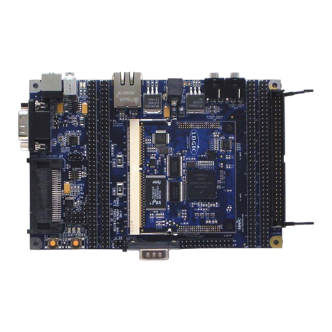
Logic Zoom i.MX LITEKIT User manual

ZOO M
QuickStart Guide www.logicpd.com
:: i.MX LITEKIT ::


ZOOM i.MX LITEKIT
Quickstart Guide
We fast forward
the evolution of
new products.

ZOOM i.MX LITEKIT
2 QuickStart Guide
Table of Contents
1Introduction 4
1.1 Zoom i.MX LITEKIT Features 4
2 Getting Started 6
2.1 Unpacking the System 6
2.2 CD-ROM Content Highlights 7
2.3 Development PC Requirements 7
2.4 Baseboard Connection Diagram 8
3QuickStart 10
3.1 Connecting the SOM-LV to the Baseboard 10
3.2 Connecting the Expansion Breakout Board to the Baseboard 11
3.3 Connecting the Baseboard to your PC 13
4 Test Drive the Zoom i.MX LITEKIT 15
4.1 Terminal Emulation Installation 15
4.2 Power-up the LITEKIT 16
4.2.1LogicLoader (Bootloader/Monitor) Power-up 16
4.3 Sample Application 17
4.4 Board Support Packages (BSPs) 17
5 Jumper/Switch Functionality 18
5.1 Jumper Settings for Zoom i.MX LITEKIT 18
6 Product Notices 19
7 Product Registration 20
8 Product Ordering Information 21
8.1 Zoom Display Kits 21
9Support 22
9.1 Frequently Asked Questions 23
9.2 Technical Discussion Group 23
9.3 Warranty Statement 23

ZOOM i.MX LITEKIT
QuickStart Guide 3
Table of Figures
Figure 2.1 – Kit Hardware Contents 6
Figure 2.2 –Connection Diagram for the Baseboard 8
Figure 3.1 – Aligning the SOM-LV over the Baseboard 10
Figure 3.2 –Connecting the SOM-LV to the Baseboard 11
Figure 3.3 –Aligning the Breakout Board over the Baseboard 12
Figure 3.4 –Connecting the Breakout Board to the Baseboard 12
Figure 3.5 –Connecting the Baseboard to your PC 14
Figure 3.6 –Baseboard JTAG Settings for i.MX27/31 SOM-LV 14
Figure 4.1 –Tera Term: Serial Port Set-up Window 15
Figure 4.2 – LogicLoader losh> Prompt 16

ZOOM i.MX LITEKIT
4 QuickStart Guide
1 Introduction
Congratulations on your purchase of the Zoom™ i.MX LITEKIT Development Kit. The Zoom
i.MX LITEKIT provides a product-ready software and hardware platform for evaluating the
functionality of the Freescale™ i.MX processor and System on Module. Logic’s embedded
solutions fast forward product development and helps your company stay focused on your
high-value core technologies.
1.1 Zoom i.MX LITEKIT Features
Common Features
+System on Module (SOM)
+SOM-LV form factor
+LCD Display Connector
+Integrated LCD, touch, and backlight connector for Zoom Display Kits
+Audio Stereo
+Input and output jacks
+PC Card Expansion
+CompactFlash® Type I card
+MMC/SD Card Support
+ATA Support
+Serial Port
+RS-232 debug serial port
+Expansion Headers
+Access to all SOM-LV signals via expansion breakout board that connects to the
baseboard through two high-density board-to-board (BTB) socket connectors
+Standard 100 mil pitch on expansion board headers
+USB
+One USB 2.0 high-speed host
+One USB 2.0 high-speed On-the-Go device
+One USB B debug device
+Network Support
+One RJ45 Ethernet jack connector with magnetics (application/debug)
Cables
+Serial cable (null-modem)
+5 volt power supply with power adapters
+Ethernet crossover cable
+USB A to mini-B cable

ZOOM i.MX LITEKIT
QuickStart Guide 5
Software
+Sample Windows® Embedded CE binary images available from Logic
+Windows Embedded CE BSP available from Logic
+Linux BSP available from third-parties
+LogicLoader™ (bootloader/monitor) installed in the SOM-LV flash
Application Development Tools
+Cygwin, Tera Term, and GNU Cross Development Toolchain
Mechanical
+LV-Baseboard form factor baseboard
+158.8 mm long x 146.1 mm wide x 17.1 mm high
+i.MX31 SOM-LV Type I form factor SOM
+76.2 mm long x 59.1 mm wide x 7.9 mm high
+i.MX27 SOM-LV Type II form factor SOM
+76.2 mm long x 50.8 mm wide x 7.9 mm high

ZOOM i.MX LITEKIT
6 QuickStart Guide
2 Getting Started
2.1 Unpacking the System
The Zoom i.MX LITEKIT includes the following items:
+Application baseboard
+SOM-LV
+Expansion breakout board
+CD-ROM (see "CD-ROM Content Highlights" Section)
+Null-modem serial cable
+Ethernet crossover cable
+USB A to mini-B cable
+5 volt power supply with power adapters (Europe, Japan, UK, and US)
+End-User License Agreement
+Warranty card
+QuickStart Guide
+Freescale TIC card
Note: Avoid touching the MOS devices. Static discharge can and will damage these devices.
Once you have verified that all the items are present, remove the board from its protective
jacket and anti-static bag. Check the board for any visible damage and ensure that there are
no broken, damaged, or missing parts.
Figure 2.1 – Kit Hardware Contents
SOM-LV
CD-ROM
Regulated 5 volt
Power Supply
Null-modem
Serial Cable Ethernet
Cross-over Cable
Application Baseboard
Power Adapters
(Europe,Japan,
UK,andUS)
Expansion Breakout Board
USB A to
mini-B Cable

ZOOM i.MX LITEKIT
QuickStart Guide 7
2.2 CD-ROM Content Highlights
Product Documentation
+SOM-LV and LITEKIT product briefs
+Bill of Materials1(.pdf format) for SOM-LV, application baseboard, and expansion
breakout board
+Schematics1for SOM-LV (.pdf format), application baseboard (.pdf and .DSN
formats), and expansion breakout board (.pdf and .DSN formats)
+Layouts1for SOM-LV (.pdf format), application baseboard (.pdf and .MAX formats),
and expansion breakout board (.pdf and .DSN formats)
+SOM-LV Hardware Specification
+Zoom i.MX LITEKIT User’s Manual
+LogicLoader User’s Manual
+LogicLoader User’s Manual Addendum
+i.MX27/31 Reference Manuals available for download from Freescale’s website
http://www.freescale.com/iMX
Software Development Tools (Refer to each tool’s readme file for instructions)
+Te r a Te r m
+Cygwin1
+GNU cross development toolchain1
References, Resources, and Support
+FAQ
+Technical Discussion Group (TDG)2
+How to get technical support (Ask a Question)
+Support Packages
Product Registration & Software Downloads
2.3 Development PC Requirements
General
+Windows® 2000 or later host PC with access to the Internet
+Pentium® processor or equivalent
+64 MB RAM minimum
+115200 baud capable RS-232 port (COM port) or USB port (see "Connecting the
Baseboard to your PC" Section)
+Tera Term serial emulation program (or equivalent)
1. Available as downloads from Logic’s website. Please create an account and
register your product to access and be notified of the latest updates to these
documents: https://www.logicpd.com/auth/.
2. Please note that the TDG site requires its own account creation that is separate
from the account used for the main Logic website.

ZOOM i.MX LITEKIT
8 QuickStart Guide
2.4 Baseboard Connection Diagram
Figure 2.2 – Connection Diagram for the Baseboard
BACD
EFG I
K
L
M
N
J
UV
H
O
P
QRST

ZOOM i.MX LITEKIT
QuickStart Guide 9
Connection Diagram Details
A – Power-in from 5 volt regulated power supply
B – USB B debug device
C – Serial port—115.2 kbps RS232 debug serial port
D – Ethernet speed LED
E – Ethernet link/activity LED
F – RJ45 Ethernet jack with magnetics
G– USBhost
H – USB On-the-Go mini-AB port
I – Line-in stereo 3.5 mm jack
J – Line-out stereo 3.5 mm jack
K – 40-pin ATA header
L – 60-pin header for integrated LCD, touch, backlight, connector power
M – 240-pin BTB socket connectors for expansion breakout board
N – System reset button
O – System wake-up button
P – System power on/off button
Q– PoweronLED
R – ATA activity LED
S– GPIO0LED
T– GPIO1LED
U – CompactFlash Type I card
V – MMC/SD card

ZOOM i.MX LITEKIT
10 QuickStart Guide
3 QuickStart
3.1 Connecting the SOM-LV to the Baseboard
The SOM-LV connects to the baseboard via two BTB socket connectors.
1. Align the SOM-LV over the two connectors farthest in from the edge of the board.
See Figure 3.1. (There is an outline of the SOM-LV on the baseboard silkscreen to
show proper placement.)
2. Press the SOM-LV straight down, applying even pressure, onto the two baseboard
socket connectors. See Figure 3.2.
3. Verify that the socket connectors on the SOM-LV and baseboard have mated
correctly. To remove the SOM-LV, pull up on the board above the socket
connectors. Attempt to pull straight up and refrain from flexing the printed circuit
board (PCB) to avoid damaging the SOM-LV.
Figure 3.1 – Aligning the SOM-LV over the Baseboard

ZOOM i.MX LITEKIT
QuickStart Guide 11
Figure 3.2 – Connecting the SOM-LV to the Baseboard
3.2 Connecting the Expansion Breakout Board to the Baseboard
Use of the expansion header breakout board is required to access all of the SOM-LV’s
signals. The expansion header breakout board connects to the baseboard via two BTB
connectors.
1. Align the breakout board over the two BTB connectors closest to the baseboard
edge. See Figure 3.3. (There is an outline on the baseboard silkscreen that
specifies the expansion breakout board connectors). When aligned correctly, the
majority of the expansion breakout board will overhang the side of the baseboard.
2. Press the breakout board straight down, applying even pressure, onto the two
baseboard socket connectors. See Figure 3.4.
3. Verify that the socket connectors on the breakout board and baseboard have
mated correctly. To remove the breakout board, pull up on the board above the
socket connectors. Attempt to pull straight up and refrain from flexing the PCB to
avoid damaging the breakout board.

ZOOM i.MX LITEKIT
12 QuickStart Guide
Figure 3.3 – Aligning the Breakout Board over the Baseboard
Figure 3.4 – Connecting the Breakout Board to the Baseboard

ZOOM i.MX LITEKIT
QuickStart Guide 13
3.3 Connecting the Baseboard to your PC
1. Connect the null-modem serial cable (supplied in the kit) to the serial port
connector on the baseboard and to a COM port on the host PC. See Figure 3.5.
Note: If your computer does not contain a serial port, you can use the USB B
device on the baseboard to connect to the USB port on your computer. See Figure
3.5. The application baseboard is equipped with an FTDI virtual COM port (VCP)
chip that causes the USB device to appear to your computer as an additional COM
port. Settings for the terminal emulation program will remain the same; however, a
driver must be installed on your computer and a USB A-to-B cable must be
purchased separately for proper operation. A link to the driver and instructions for
using the FT232R VCP chip can be found at
http://www.logicpd.com/auth/downloads/i.MX LITEKIT/.
2. Confirm baseboard JTAG jumpers are set for normal operation with your specific
SOM-LV, as shown in Figure 3.6.
Note: For proper JTAG operation, the jumpers should remain in the normal
operation position.
3. Connect the regulated 5 V power supply to the appropriate power adapter. Plug
the power adapter into an electrical outlet and the 5 V line output connector into
the power connector on the baseboard.
4. Press the power on button to boot the LITEKIT. See Figure 3.5.

ZOOM i.MX LITEKIT
14 QuickStart Guide
Figure 3.5 – Connecting the Baseboard to your PC
Figure 3.6 – Baseboard JTAG Settings for i.MX27/31 SOM-LV
RS-232 null-modem cable to host PC
Power supply & power adapter
(Europe, Japan, UK, or US)
Power on button
USB B debug device
1
2
6
5
JP2
Normal and JTAG operation

ZOOM i.MX LITEKIT
QuickStart Guide 15
4 Test Drive the Zoom i.MX LITEKIT
4.1 Terminal Emulation Installation
The Zoom i.MX LITEKIT is designed to communicate with terminal emulation programs using
the included null-modem serial cable and the following settings: 115200 baud, 8-data-bits,
no-parity, 1-stop-bit, and no-flow-control. The terminal emulation program must support
binary transfers in order to download software to the kit.
Although Logic Product Development does not support any particular terminal emulation
program, we suggest using Tera Term Pro for Windows® 2000 or Windows XP. Tera Term Pro
is provided on the CD-ROM or can be downloaded for free from Logic’s website:
https://www.logicpd.com/auth/. Tera Term Pro is not available for Linux users. Logic Product
Development does not guarantee or support any terminal emulation programs.
Once the terminal emulation program has been installed, open a new serial port connection
using the COM port where the null-modem serial cable is connected to the host PC. Set the
‘baud-rate’ to 115200, ‘data’ to 8-bit, ‘parity’ to none, ‘stop’ to 1-bit, and ‘flow control’ to
none. (Hint: In Tera Term, you can save these serial port settings by selecting ‘Setup -> Save
setup...’ from the file menu. After saving, these serial port settings will be in place every time
you launch the Tera Term application.)
Figure 4.1 – Te r a Te r m : S e r i a l P o r t S e t - u p W i n d o w

ZOOM i.MX LITEKIT
16 QuickStart Guide
4.2 Power-up the LITEKIT
The Zoom i.MX LITEKIT is shipped with the Logic bootloader installed in resident flash.
LogicLoader provides the capability for loading operating systems and applications. In
addition, it provides a full suite of commands for interfacing to the SOM-LV. These commands
load operating systems, configure hardware platforms, bring up hardware, customize
applications, perform tests, and manage in-field devices.
4.2.1LogicLoader (Bootloader/Monitor) Power-up
The SOM-LV is shipped with a version of LogicLoader (bootloader/monitor) programmed into
the boot flash device at an offset of 0xA000_0000.
Accessing LogicLoader
Interface to LogicLoader via a terminal emulation program connected via a null-modem serial
cable to the “Terminal” port of the SOM-LV (debug serial port on the baseboard). Use the
following default terminal settings: 115200 baud, 8-data-bits, 1-stop-bit, no-parity, and
no-flow-control.
1. Start a terminal program on the host PC (e.g., Tera Term, HyperTerminal).
2. Connect a serial cable to the host PC and to the serial port on the baseboard.
3. Connect power supply to the LITEKIT.
4. Press the power on button (see Figure 2.2 for button location).
5. In the terminal program you should see a LogicLoader screen similar to that below.
Figure 4.2 – LogicLoader losh> Prompt

ZOOM i.MX LITEKIT
QuickStart Guide 17
4.3 Sample Application
The Zoom i.MX LITEKIT comes with a sample application that can be downloaded from the
Logic website: https://www.logicpd.com/auth/. For instructions, see the Zoom i.MX LITEKIT
User’s Manual and the readme file that accompanies the downloaded sample application.
4.4 Board Support Packages (BSPs)
Logic offers various product-ready Board Support Packages (BSPs) in binary format for Zoom
Development Kits.
Logic provides sample downloadable evaluation Windows Embedded CE images (NK.bins)
to evaluate the Windows Embedded CE operating system on Logic's line of Development
Kits. These sample images are provided as part of the Microsoft® Windows CE Hardware
Kitting Program. Logic packages a 120-day evaluation version of Windows Embedded CE
Platform Builder in the Development Kit and posts downloadable sample images on the Logic
website. These images are licensed for evaluation purposes only and are not intended for
commercial use. Please reference Application Note 296 entitled When to Use an NK.bin for
information about the capabilities of the binary OS images.
If your development effort requires the use of a BSP, Logic provides a binary BSP as a
downloadable item from the website. In order to obtain Logic’s Windows Embedded CE BSP,
please read and sign the Windows CE BSP License Agreement located at:
http://www.logicpd.com/downloads/406/.

ZOOM i.MX LITEKIT
18 QuickStart Guide
5 Jumper/Switch Functionality
5.1 Jumper Settings for Zoom i.MX LITEKIT
The following table describes the function of the jumpers on the application baseboard.
Table 5.1 – Jumper Switch Table
Jumper Settings Function
JP2 Jmp 5
Jmp 6
Normal operation. An individual jumper is
placed on each pin and not connected to
another pin. (See Figure 3.6, earlier in this
document.)
JP3 Jmp 2–3 ATA Operating Voltage. Default is when
jumper is across pins 2 and 3.
JP4 Jmp 1
ATA Enable. When the jumper is placed
only on pin 1 and not connected to
another pin, ATA functionality is enabled
for the board.
Table of contents
Other Logic Microcontroller manuals
Popular Microcontroller manuals by other brands

Telit Wireless Solutions
Telit Wireless Solutions Cinterion LGA DevKit user guide

GigaDevice Semiconductor
GigaDevice Semiconductor GD32F20 Series user manual

Altera
Altera Stratix IV GX Reference manual

Texas Instruments
Texas Instruments MSP430G2955 manual

Motorola
Motorola M68MPB334 user manual

sparkfun
sparkfun QuickLogic Thing Plus HOOK-UP GUIDE

Segger
Segger J-Link user guide

ST
ST FP-SNS-SMARTAG1 quick start guide

STMicroelectronics
STMicroelectronics STM32L151CCT6 manual

Digilent
Digilent chipKIT Uno32 Reference manual

Microchip Technology
Microchip Technology Digital Power Starter Kit user guide

PLX Technology
PLX Technology PEX 8509RDK Hardware reference manual