manuals.online logo
Brands
  1. Home
  2. •
  3. Brands
  4. •
  5. LogicLadder
  6. •
  7. Inverter
  8. •
  9. LogicLadder EnergyLogicIQ User manual

LogicLadder EnergyLogicIQ User manual

Installation Instruction
EnergyLogicIQ Generator
Read the instruction guide carefully before the installing and the first use of the EnergyLogicIQ
Generator
1. Insert GSM/GPRS SIM in the device SIM Slot 1, ensure the SIM has an active data pack and can receive
SMS
OR
2. Connect to a DHCP & internet enabled Ethernet network via the Ethernet port.
3. Power on the device by connecting the 24V DC power adapter provided.
4. Sign In into https://generator.energylogiciq.com using your username or password.
5. If this is the first device, you will automatically guide on the screen through a wizard to provision your
device.
6. If this is your second or subsequent device click on Click on icon in the right top corner.
7. Click on “Manage Devices” menu item
8. Click on “Add Device”. This will open up the configuration wizard. Follow the instructions on the screen
to provision a new device and create associated sites, generators, and tanks.
9. Once you have provisioned the device and it's online on the platform proceed to site for installation
and install the IoT cloud connector. Please refer to the wiring diagram on the next page for details.
Tools Required: Measuring tape, Hexa, screw driver set, multimeter, drill machine, cutter etc.
IMP! These instructions are for 300, 500, 1000 mm range sensors. For sensors with greater range
consult the respective sensor manual.
⚠ WARNING! Empty the diesel tank before carrying out any installation work. Follow the local safety
regulations in your country.
1. Empty and clean the tank of residual oil, sludge, gas etc.
100mm 100mm
a. Mount the sensor on the tank and empty the
fuel tank for calibration at minimum fuel level.
Empty Tank
Ultrasonic
Pulse Beam
Ultrasonic
Transducer
Process Fluid
Correct Installation
b. Calibrate by applying -UB to the Teach-In
input (yellow LED flashes).
Apply -UB to tech-In
until yellow LED flashes
-UB Tech-In
Remove
Iron Filing
6. Power on the sensor and calibrate it.
⚠ Avoid the iron filing from falling
into the tank, you can use a strong
magnet to attract them and prevent
them from falling into the tank.
4. Mount the ultrasonic sensors with a plastic gasket to avoid acoustic energy absorption through the
sensor body.
5. Drill the smaller sensor mounting holes to match sensor gasket holes.
c. Disconnect the Teach-In input from -UB to
save the min level calibration.
Disconnect -UB from Teach-
In for saving calibration
-UB
d. Now fill the tank with diesel to the maximum
level.
Full Tank
Clean Tank
Step 2: Ultrasonic Fuel Level Sensor Installation
Step 1: IoT Cloud Connector Provisioning (Do this before going to site)
f. Disconnect the Teach-In input from +UB to
save the maximum level calibration.
Apply +UB to tech-In
until yellow LED flashes
+UB Tech-In
Disconnect +UB from Teach-
In for saving calibration
+UB Tech-In
e. Calibrate for maximum level by applying +UB
to the Teach-In input (yellow LED flashes).
⚠ WARNING! Qualified Electrician should perform this job only and in accordance with local regulations.
1. Calculate the right CT and PT required based on your load and voltage levels to bring current and
voltage in the input range of the energy meter (6A current and 350 L-N Voltage).
P1 should be always in the current source direction and P2 should always be in the load direction.
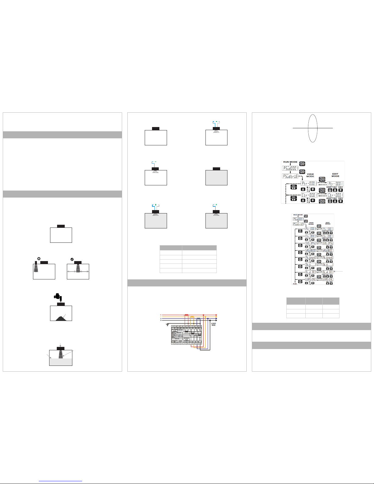
3. Check and set up the following energy meter settings. Check out the manual for more details:
Full Tank
Step 3: Energy Meter Installation
2. Select the drilling point on the center of the oil tank surface at least 100 mm away from any
sidewall. Corner installation will cause inner wall reflection and erroneous readings.
3. Use an appropriately sized hole saw, based on the sensor size, to drill the sensor mounting holes.
2. Install the CT and PT as per the diagram below. This configuration is a 4-wire 3 phase (star) system for
any other configurations (like Delta) please refer to the installation manual.
> >
P1 P2
From Source To Load
CT Coil Connection Diagram
a. CT & PT ratio
b. 485 communication and modbus settings
Device
Modbus Address
(Generator 1)
Modbus Address
(Generator 2)
Energy Meter
1
2
Flow Meter
3
4
Generator Controller
5
6
Step 4: Connect Generator Battery
⚠ WARNING! batteries of higher voltage (greater than 30V) can damage the unit.
Please refer to the wiring diagram on the next page for details.
Step 5: Connect Generator on/off PFC
⚠ WARNING! Connecting signal of higher voltage (greater than 30V) can damage the unit. 5V < Signal DC
Voltage < 30V
Please refer to the wiring diagram on the next page for details.
Configure modbus address for energy meters as per the following table:
Cable Color
Definition
Brown
Power Supply typical (+UB)
Blue
Power Supply Ground(-UB)
Black
Current output(4-20mA)
White
Teaching input
Grey
Synchronization
MODBUS SLAVE
ADDRESS
GSM
ANT
GPS
ANT
SD Card Ethernet SIM Card 2 F/W UPGR
SIM Card 1
+-
BATTERY 1
FUEL TANK
FUEL LEVEL
SENSOR
+
420mA
Current I/P Digital Input +
Power
24VDC
-
VDC I/P Digital Output
+-
12
+-+-
12
+-
+-
12
+-
+-
34
+-
+-
12
+
POWER
SUPPLY
>5VDC
ON +
-
GENERATOR STATUS
-
www.logicladder.com
Sensor / Device
Ports
Channel/Address
Fuel Level Sensor 1
Current I/P
1
Fuel Level Sensor 2
Current I/P
2
Fuel Level Sensor 3
Current I/P
3
Fuel Level Sensor 4
Current I/P
4
Battery 1
VDC I/P
1
Battery 2
VDC I/P
2
On/Off status 1
Digital Input
1
On/Off status 2
Digital Input
2
Energy Meter 1
RS 485
Modbus Address 1
Energy Meter 2
RS 485
Modbus Address 2
Flow Meter 1
RS 485
Modbus Address 3
Flow Meter 2
RS 485
Modbus Address 4
Controller 1
RS 485
Modbus Address 5
Controller 2
RS 485
Modbus Address 6
TB-
TA+
DATA-
DATA+
ENERGY METER 2
RS484 A
RS484 B
ENERGY METER 1 FLOW METER 1
CONTROLLER 2
CONTROLLER 1
TB-
TA+
DATA+
DATA-
RS484 A
RS484 B
FLOW METER 2
BK
BN
BU
+ 24VDC -
WARNING! Connecting signal
of higher voltage (greater than
30V) can damage the unit. 5V <
Signal DC Voltage < 30V
WARNING! batteries of
higher voltage (greater than
30V) can damage the unit
WARNING! Qualified
Electrician should perform this
job only and in accordance
with local regulations
WARNING! Empty the diesel tank
before carrying out any installation
work. Follow the local safety
regulations in your country.
Connection with EnergyLogicIQ Generator
BACK SIDE
VODAFONE
RIGHT SIDE
RS485 RS232
DEBUG
+-
Sensor
BU

Other manuals for EnergyLogicIQ

1

Popular Inverter manuals by other brands

Siemens MICROMASTER 420 operating instructions

Siemens

Siemens MICROMASTER 420 operating instructions

Mastervolt WHISPER 25 ULTRA installation manual

Mastervolt

Mastervolt WHISPER 25 ULTRA installation manual

Micno KE300A Series manual

Micno

Micno KE300A Series manual

SMA 9000TL installation guide

SMA

SMA 9000TL installation guide

Afore AF1K-SL-0 Installation and operation manual

Afore

Afore AF1K-SL-0 Installation and operation manual

ABB PVI-8.0-TL-OUTD product manual

ABB

ABB PVI-8.0-TL-OUTD product manual

s-rack Sigma S1 installation manual

s-rack

s-rack Sigma S1 installation manual

Hoymiles HM-600T user manual

Hoymiles

Hoymiles HM-600T user manual

CHISAGE CE-3P12K1G-LE-EU user manual

CHISAGE

CHISAGE CE-3P12K1G-LE-EU user manual

Siemens SINAMICS G120P instruction manual

Siemens

Siemens SINAMICS G120P instruction manual

EG4 18KPV user manual

EG4

EG4 18KPV user manual

Agilent Technologies E4412A Operating and service guide

Agilent Technologies

Agilent Technologies E4412A Operating and service guide

Western W-HHS-3000 user manual

Western

Western W-HHS-3000 user manual

Cotek S1500-112 user manual

Cotek

Cotek S1500-112 user manual

ABB PVI-3.0-TL-OUTD Quick installation guide

ABB

ABB PVI-3.0-TL-OUTD Quick installation guide

Tamarack Solar STP-LCR-R Series installation manual

Tamarack Solar

Tamarack Solar STP-LCR-R Series installation manual

Hyundai J300 series instruction manual

Hyundai

Hyundai J300 series instruction manual

Tronic TSW 150 A1 operating instructions

Tronic

Tronic TSW 150 A1 operating instructions

manuals.online logo
manuals.online logoBrands
  • About & Mission
  • Contact us
  • Privacy Policy
  • Terms and Conditions

Copyright 2025 Manuals.Online. All Rights Reserved.