STP-LCR-R Series
1
Table of Contents
Introduction
............................................................................................................................................................... 1
Customer Support
..................................................................................................................................................... 1
Tools Required
............................................................................................................................................................ 1
Components List
:....................................................................................................................................................... 1
Pre Assembly for Model STP-LCR/120
.................................................................................................................... 2
Step 1
:
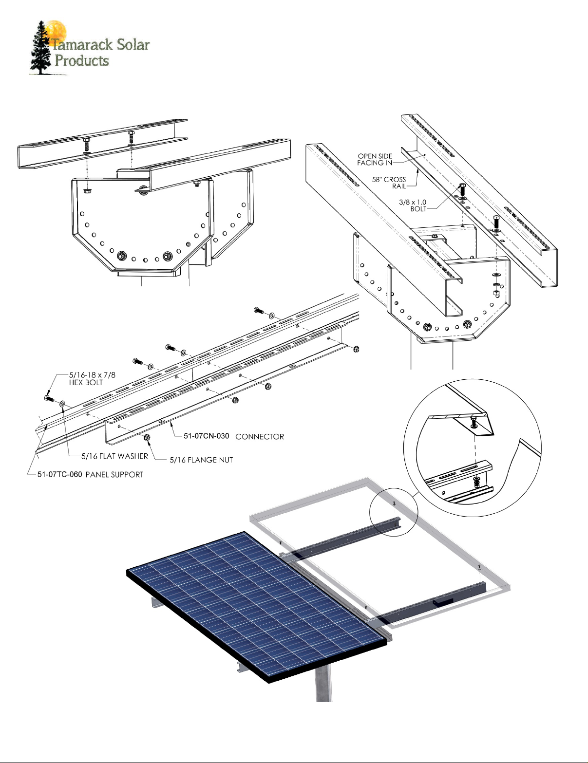
Connecting Panel Support Channels
.......................................................................................................... 3
Step2
:
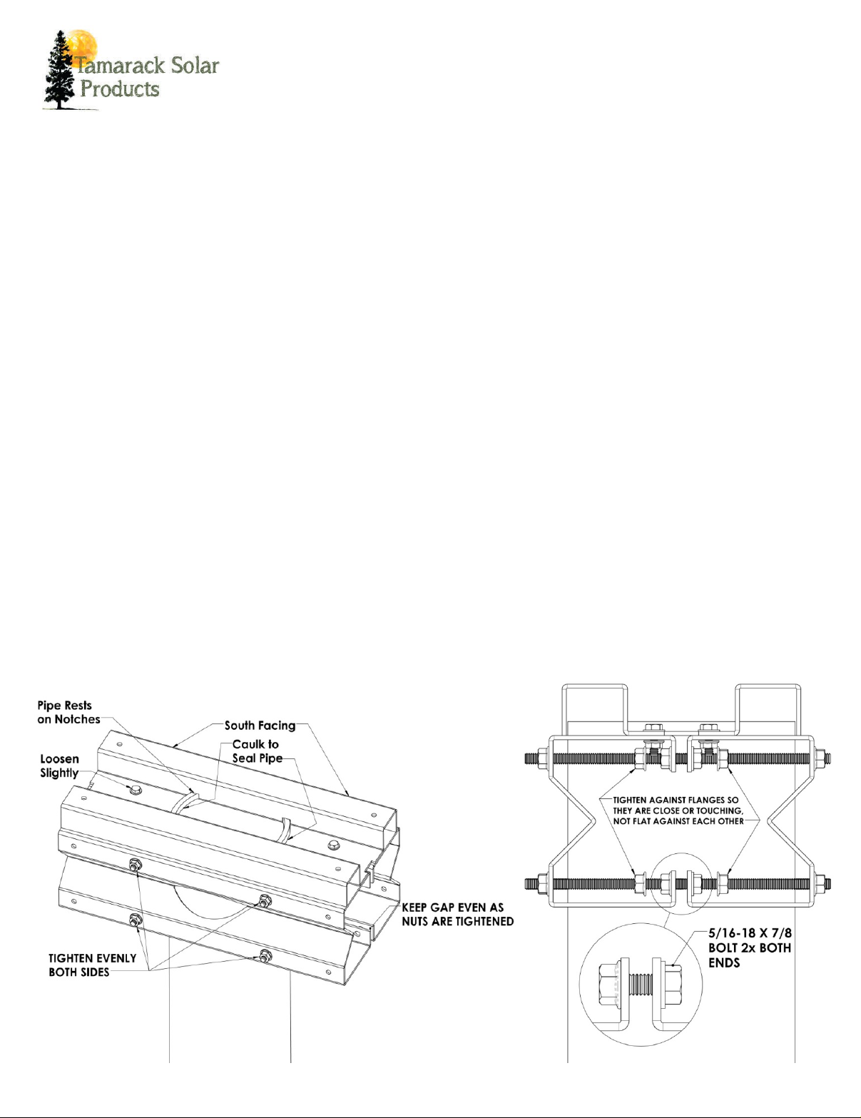
AttachPole Clamp Assembly toPole
........................................................................................................... 3
Step 3: Attach Tilt Plate Mounting Channel
.......................................................................................................... 3
Step 4: Attach Tilt plates
......................................................................................................................................... 3
Step 5: Attach Cross Rails to Tilt Plates.
................................................................................................................. 4
Step 6: Attach Panel Supports to Cross Rails
........................................................................................................ 4
Step 7 Attach Panels to the supports....................................................................................................................... 4
Step 8: Adjust Tilt Angle
........................................................................................................................................... 4
Detailed Diagrams for Assembly
............................................................................................................................. 4
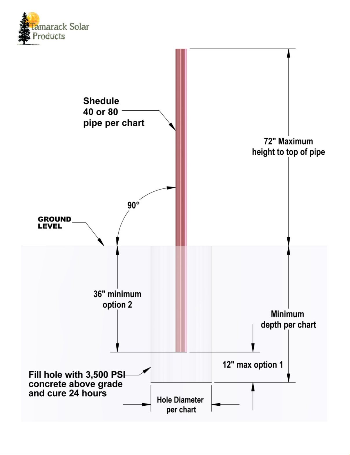
Foundation Hole Guidelines...........................................................................................Error! Bookmark not defined.
InstallerResponsibility
............................................................................................................................................... 9
Warranty Information .............................................................................................................................................. 11
Introduction
The Top of Pole Mount is an extremely sturdy, universal pole mounting solution for small area
solar
photovoltaic (PV) needs. With its user adjustable angle settings (0° to 60° in 10° increments), the Top
of Pole Mount can support installations in a wide
range of locations.
Customer Support
Tamarack Solar makes every effort to ensure your
m
ounting kit is easy to install. If you need
assistance at any point in your installation or have suggestions on how
we can improve your
experience, call customer
support at 1-800-819-7236 or email us at info@tamaracksolar.com
Tools Required
Tools that support the following size Hex heads: Torque values are “dry”, add 15% if using anti-seize lubricant on
Stainless hardware (Recommended). A deep socket or short extension needed for 3/8”, in one location.
1. 3/8”= 240\20 In\Ft Lbs
2. 5/16”= 144\12 In\Ft Lbs
3. 1/4"= 84\7 In\Ft Lbs
Components List
: