Logo Lites USB Charge Port User manual

USB Charge Port Installation Instructions
Lifetime Technical Support
770-476-7322
www.logolites.com
Manual 100-0014B

Thank you for purchasing a Logo Lites® USB Charge Port!
USB Charge Port Overview
•Works ith 6V and 12V automotive electrical systems.
•Provides t o, independent USB Type A Dedicated Charge Ports for
universal charging.
•Automatically turns on and off the USB Charge Ports hen your
engine starts and stops (6V/12V only – not automatic for 8V).
•Will not discharge your vehicle battery hen not in use (less than
0.0001 Amp current dra hen off).
•Green LED indicates hen USB po er is available.
•Press the override button for 10 seconds to turn on USB Charge Port for t o hours hen engine is off.
•USB Charge Port has thermal and overload safeties and includes protection for plugged in devices.
Safety Information
•Read the instructions completely before starting the installation.
•Never attempt automobile iring ithout first disconnecting the battery.
•Ensure you kno here iring, fuel, brake, and other critical systems are located in the vehicle.
•When using po er tools such as a drill, be sure to use the proper safety equipment (eye protection, etc.).
Al ays follo manufacturer’s recommendations hen using po er and hand tools.
•The installation discussed is for reference only and does not indicate that any particular
configuration will be safe for all vehicles. A safe and secure installation is solely the responsibility
of the installer!!
Tools & Supplies Needed
USB Charge Port installs ith simple hand tools found in the average home mechanic’s toolbox. Required
tools are different for every installation, but a ire crimp tool is required unless you plan to solder your
connectors. Some installations ill need a drill and 9/64” drill bit. It may be helpful to have tie raps to
suspend ires for a complete installation. A multimeter is helpful to locate po er and chassis connections, and
to troubleshoot any connection issues.
Before Installation: etermine Chassis Polarity
It is very important to determine if your vehicle is positive or negative chassis. Look at your battery in your
vehicle. There are t o battery cables. One is connected from the battery to the starter or the starter solenoid.
The other battery cable is connected from the battery to the frame or engine. The cable that connects to the
frame or engine tells hich polarity your chassis is. Look at the battery here the cable from the frame or
engine connects. If that post has a + marking on the battery, you have a positive chassis. If there is a – on that
battery post, you have a negative chassis. It is important to note if your vehicle is negative or positive chassis
and to follo the appropriate right instructions belo .
Choose Installation Type
USB Charge Port mounts to your vehicle or to an A-Plate™, if available for your vehicle. Instructions for both
Conventional and A-Plate installations are available belo .
Tip – A wire that is too exact in length is difficult to connect. A wire that has too much slack looks sloppy and is easily
caught in tools and other equipment. When cutting power wires, pull the wire tight between the two points the wire
must span, and then add 1 to the length of the wire before cutting. Adjust this 1 general guideline for your needs
using your own best judgment. Remember, it is easy to trim a wire shorter, but not so easy to make it longer.

Before proceeding to the A-Plate or Conventional instructions belo , unscre the t o scre s
in the Input Connector several turns counter clock ise so that there is enough room for
stripped ires to be inserted into the small clamps. The Input Connector color may vary from
the one pictured to the right.
Installation on a Logo Lites A-Plate:
If the A-Plate is already installed, disconnect vehicle battery and remove the A-Plate from the vehicle.
Use t o #8-32 scre s and nuts to mount the USB Charge Port to an available location on your A-Plate
ith the Input Connector facing up and the USB ports facing do n.
Choose an available fuse terminal for your USB Charge Port.
Cut red ire to length to reach from fuse terminal to the Input Connector.
Cut black ire to length to reach from the chassis terminals of the fuse block to the Input Connector.
Strip 1/4” of insulation off of both ends of the red and black ires.
Crimp non-insulated 1/4” female quick disconnect terminal onto black ire.
Crimp insulated 1/4” female quick disconnect terminal onto red ire.
Follo the next step(s) based on the positive or negative chassis polarity you noted earlier:
Positive Chassis
Looking into the connector’s ire holes ith
the scre heads up, insert stripped end of red
ire into left hole of the Input Connector and
tighten the scre to hold the ire snugly.
Repeat for the black ire into the other (right)
hole of the Input Connector.
egative Chassis
Looking into the connector’s ire holes ith
the scre heads up, insert stripped end of black
ire into left hole of the Input Connector and
tighten the scre to hold the ire snugly.
Repeat for the red ire into the other (right)
hole of the Input Connector.
Fully insert Input Connector into USB Charge Port.
Push uninsulated 1/4” quick disconnect terminal of
black ire onto unused male chassis terminal on fuse
block.
Push red 1/4” quick disconnect terminal of red ire
onto the available fuse terminal you chose earlier.
Insert 3 Amp ATO fuse into the fuse slot for the
terminal you chose earlier.
Install A-Plate into your vehicle.
Connect harnesses to other devices mounted to A-Plate
if equipped.
Double check that all ires are connected safely and
correctly.
Reconnect vehicle battery.

Conventional Installation (without a Logo Lites A-Plate™):
Disconnect vehicle battery.
Choose a location to mount the USB Charge Port. The location
should be in a dry area in the interior of your vehicle. Be sure that
the ay you mount your USB Charge Port does not interfere ith or
damage your vehicle’s fuel, electrical, or safety systems. USB
Charge Port mounts ith t o #8 self threading scre s (provided).
Depending on your application, you might be able to use adhesive
backed hook and loop tape to mount your USB Charge Port (not
provided).
Tip – think about plugging USB devices into the charging ports and how you will run the power wires when choosing a
mounting location. Make sure there is room to plug in the USB cables and the power wires will not interfere with vehicle
operation.
Choose an available po er source for your USB Charge Port. The po er source should be an “al ays on”
type that has voltage even hen the vehicle engine is s itched off. Antique cars may have a stud or scre
available to connect to ith a ring terminal. Some fuse panels have a quick connect terminal labeled BAT
for this purpose. We will call the connector you choose for this purpose the “Power Connector.”
Choose an electrical connection location for the chassis ire. The chassis connection should be to a metal,
ire, dash, frame, or body location that electrically connects back to the battery. A common chassis ground
point may be available under the dash, or an existing scre may provide a chassis connection. Another
option is to drill a hole and use an included #8 self tapping scre to provide the chassis connection. We
will call the connector you choose for this purpose the “Chassis Connector.”
Note – This kit is complete for Model A Ford and many other antique vehicles, but you may need to purchase additional
electrical connectors for your vehicle’s power and chassis needs. Your local auto parts store should have taps, splices,
ring terminals, or other electrical connectors if you need them.
Drill any needed holes to mount the USB Charge Port. If mounting ith the included #8 self tapping
scre s, the holes should be 9/64” in diameter.
If necessary, drill a hole to connect the Chassis Connector.
Mount the USB Charge Port using the hex key and #8 self tapping scre s or other method of your choice.
Cut black ire to length to reach from the chassis electrical connection location you chose to the input
Input Connector.
Cut red ire to length to reach from the po er source to the USB Charge Port’s Input Connector.
Choose a location for the fuse holder. It may be installed any here in the red ire but should be located as
close to the Power Connector as possible (6” or less).
Cut red ire into t o pieces here you ant to install the fuse holder.
Crimp both pieces of red ire into the fuse holder, one on each side.
TIP – Put the fuse holder in your hand with the two metal pieces at the top and
facing you. The fuse holder is an insulation displacement type, which means you
should not cut the installation off of the wire before you crimp the fuse holder to
the wire. The wires go into the fuse holder at the bottom, through the holes
from the left and from the right. Push one wire into the right side until it hits the
middle stop. It may help to twist the wire to get it to go into the hole. Then take
the piece on the top right (with the metal in it) and fold it toward the wire until it
contacts the wire. Use pliers to squeeze it down until the latch catches.
Repeat this for the wire on the other side. This creates an inline fuse holder.
Strip 1/4” of insulation off of both ends of the red and black ires.

Crimp the Chassis Connector onto the black ire. Your Chassis Connector may be a non-insulated #8
ring terminal, female quick disconnect terminal, or other connector you chose for your chassis ground
connection earlier.
Crimp insulated #10 ring terminal, insulated female quick disconnect terminal, or other connector you
chose for your Power Connector onto the red ire.
Follo the next step(s) based on the positive or negative chassis polarity noted earlier:
Positive Chassis
Looking into the connector’s ire holes ith
the scre heads up, insert stripped end of red
ire into left hole of po er connector and
tighten the scre to hold the ire snugly.
Repeat for the black ire into the other (right)
hole of the po er connector.
egative Chassis
Looking into the connector’s ire holes ith
the scre heads up, insert stripped end of black
ire into left hole of po er connector and
tighten the scre to hold the ire snugly.
Repeat for the red ire into the other (right)
hole of the po er connector.
Fully insert Input Connector into USB Charge Port.
Connect the Chassis Connector to the vehicle chassis ground point chosen earlier. If you use the #8 non-
insulated ring terminal, insert the #8 scre through the #8 tooth asher and the ring terminal, and use the
hex key to scre it into the hole you drilled earlier.
Connect the Power Connector to the terminal, stud, scre , or other po er source point chosen earlier.
Insert 3 Amp ATO fuse into the fuse holder.
Double check that all ires are connected safely and correctly.
Tip – Use tie wraps or other means to support the wires to prevent them from damage or interference with vehicle
moving parts or systems.
Reconnect vehicle battery.

Troubleshooting
If the fuse is blo n, e-mail or call Tech Support (see front of manual) before installing a replacement fuse. In this case, a blo n fuse
indicates a problem ith the vehicle’s electrical system.
If the fuse is not blo n, but the Logo Lites USB Charge Port does not ork as expected, here are some steps to help troubleshoot the
unit. Begin ith the vehicle engine running.
1 If USB Charge Port does not turn on as expected, unplug any USB devices and press and hold the red over ride button for ten
seconds. If the green light turns on, then the device has voltage and the polarity is correct, so move to step 2. Regardless of
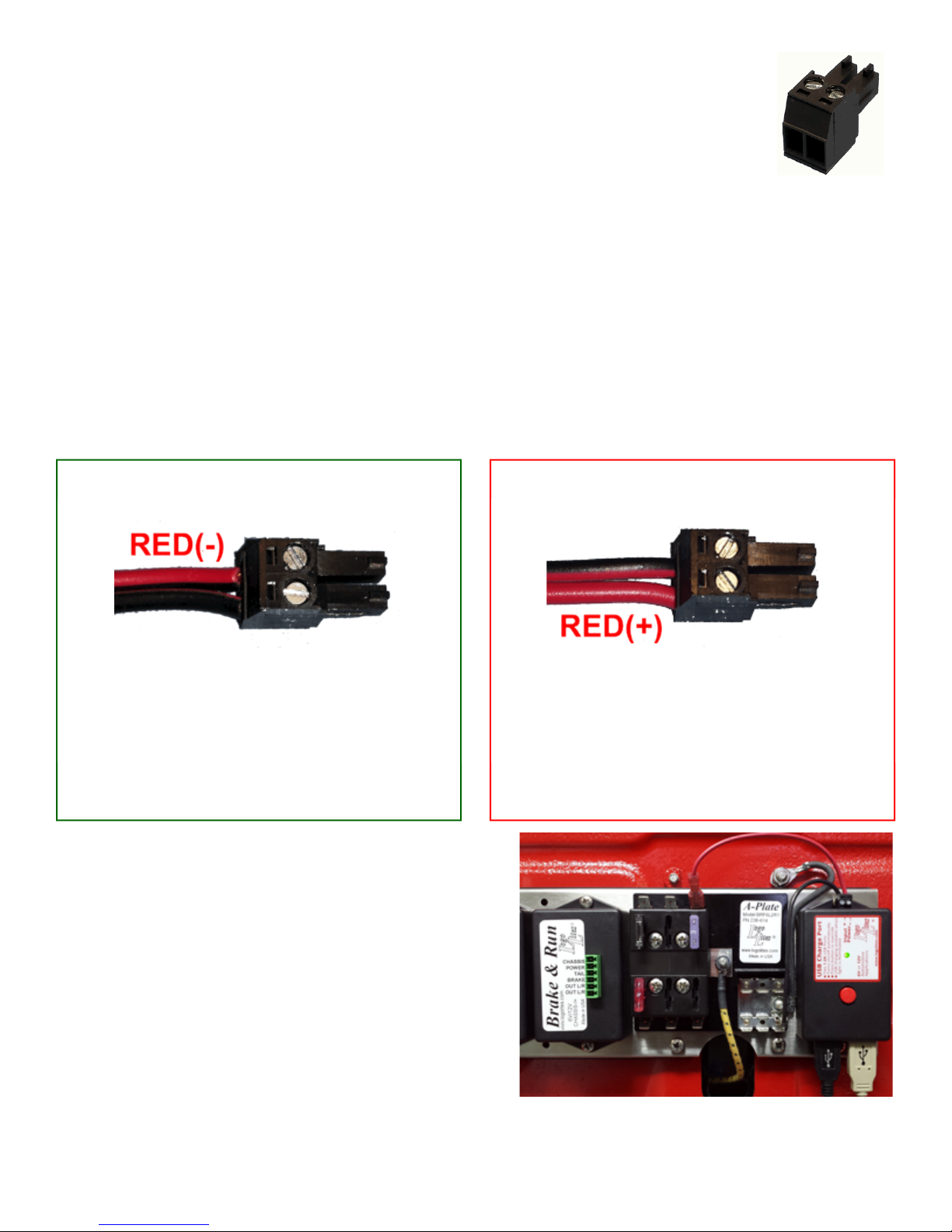
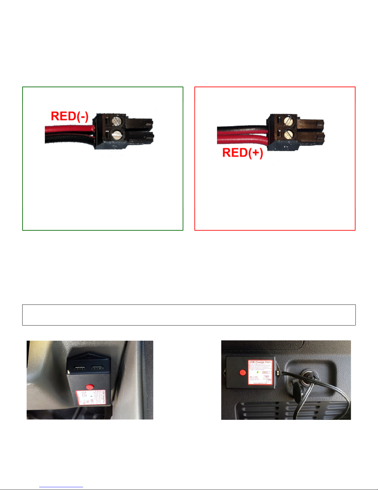
the vehicle’s chassis polarity, the + should be positive compared to the – at the Input Connector. Use a multimeter and touch
the probes to the + and – scre s and make sure there is voltage to the unit and that the voltage is positive. Check that the
Input Connector is fully inserted into the unit. Make sure the fuse is installed and not blo n. Check if there is po er
available to the fuse by touching the probes to the Power Connector and the Chassis Connector and fix as necessary.
2 If the green light turns on in override but turns off hen you plug USB device(s) in, the connections are not conducting
enough current. Make sure the Input Connector scre s are tight on the po er ires. Check the Power Connector and the
Chassis Connector. Make sure the connections are bright, clean, and free of corrosion. Clean and brighten the connections
as necessary. If the problem persists, it is likely that the Chassis Connector is not conducting enough current. Move the
Chassis Connector to another chassis location ith a better connection to the battery.
3 If the green light orks manually but does not turn on automatically there may be a battery charging issue. The automatic
start time depends upon factors that differ from vehicle to vehicle. On a vehicle ith a fully charged battery and modern
alternator in good orking order, USB Charge Port ill start about 10 seconds after the vehicle starts. Vehicles ith eak
batteries or lo current alternators or generators ill take longer to start automatically. With the green light off, start the
engine. Use a multimeter and touch the probes to the + and – scre s and measure the voltage. The USB Charge Port turns on
automatically hen an ignition signal is detected and the Input Connector voltage is bet een 6.65V – 9.0V or greater than
13.3V. With the vehicle running, if the Input Connector connector does not reach these voltages ithin a fe minutes of
driving, then the vehicle battery is not being charged properly. In this case the generator, regulator, or alternator needs to be
adjusted or serviced. USB Charge Port will only work automatically with a properly operating charging system.
4 If USB Charge Port turns on automatically and manually but doesn’t charge your device then a different USB Cable is
needed. USB cables come in t o different types kno n as ‘data cables’ and ‘charging cables’. Data cables are used for
transferring data to or from USB devices, such as copying pictures from a phone to a computer. Data cables ill charge a
USB device, but at a slo rate. They may charge a device overnight, but not provide enough current to run a GPS navigation
device all day long on a road trip for example. Charging cables have heavier gauge ires and conduct more current to USB
devices. Use USB cables marketed as ‘charging cable’ for best performance from your USB Charge Port.
Parts List
Qty escription Qty escription Qty escription
3 Screw #8 x ½ self tapping 1 Tooth washer #8 1 Hex key (wrench)
1 Quick disconnect red insulated terminal 1 Quick disconnect non-insulated terminal 1 Logo Lites screwdriver
1 #10 ring insulated terminal 1 #8 ring non-insulated terminal 1 2-pin plug
1 Red wire 1 Black wire 1 3 Amp ATO fuse
1 Blade fuse holder
Warranty
Creative Connections, Inc. (hereinafter “CCI”) warrants to the Purchaser of this unit that this unit will be free of defects in workmanship and materials for a period of
one (1) ear from the date of purchase. “Defects” as used herein, refer onl to those imperfections which impair the utilit of the product. Defective units reported or returned to
CCI within one (1) ear from date of purchase will be exchanged or repaired without charge at the option of CCI.
This warrant is limited to the repair or exchange of the product and does not cover and CCI will not pa nor provide an other benefit or service including labor or
materials which ma be necessar to remove or replace a defective unit. CCI shall not be liable for an injur , loss or damage, direct or consequential, arising out of the use or
failure of this product. It is the user’s responsibilit to determine the suitabilit of this product for its intended use. User assumes an and all risk or liabilit in connection with the
installation and use of this product. This warrant does not appl to an defects resulting from abuse, negligence, intentional damage, modification, improper installation,
unreasonable use, exposure to elements, or over-tightening of fasteners.
Defective units should be reported directl to CCI and not to our retailer. Contact CCI b telephone or write to the address shown in this manual. Identif the Logo
Lites product purchased, the date and location of purchase, and the nature of the alleged defect. Do not ship our product back to CCI unless and until specificall directed to
do so. Shipping instructions will be provided to ou at the appropriate time. Shipping to CCI is the responsibilit of the purchaser. All defective products returned must be
accompanied b proof of purchase.
This warrant is not transferable and applies onl to products sold within the United States of America, the District of Columbia, the Commonwealth of Puerto Rico,
territories of the United States, and Canada.
This limited warrant is in lieu of all other express warranties. CCI shall not be liable to an special, incidental or consequential damages. An implied warrant of
fitness for a particular purpose, merchantabilit or otherwise, applicable to this product, shall be limited in duration to the duration of this limited warrant . Some states do not
allow the exclusion or limitation of incidental or consequential damages, so the above limitation or exclusion ma not appl to ou.
“Logo Lites” and the Logo Lites logo are registered trademarks of Creative Connections, Inc.
© 2017
Creative Connections, Inc.
3407 Duluth Highwa 120
Duluth, GA 30096, USA
Table of contents